Design of 8000 rpm Multi-Slot Generators
Flur R. Ismagilov, Vyacheslav E. Vavilov, and Ruslan R. Urazbakhtin*
Abstract—In this paper 8000 rpm generators with the magnetic cores made of amorphous low-coercivity material and electrotechnical steel were designed. The sizes of the magnetic cores of generators were calculated analytically. Computer simulations of the generators under study were carried out to obtain a complete pattern of the magnetic field distribution in the magnetic cores and to estimate the generator losses. Experimental models of the generators were also made, which were studied at no load and with load. A special bench with a torque sensor was used for experimental studies.
1. INTRODUCTION
It is effective to use amorphous low-coercivity materials (ALM) to minimize losses in the magnetic cores of electric machines and transformers [1–3]. ALMs are precision low-coercivity alloys that do not have a crystal lattice. ALMs have increased hardness. ALMs are produced as a 25–30µm thick tape. However, application of ALMs is technologically limited. It is not economically feasible to manufacture ALM magnetic cores by stamping. The laser cutting and electric erosion cutting used in the manufacture of the ALM magnetic cores lead to a significant deterioration in the ALM properties. All these aspects of the ALM magnetic cores manufacture are determined by the high hardness of ALMs.
The research team of FSBEI HE “UGATU” has developed a new technology to make stators from ALMs [4]. Prototypes of ALM magnetic cores for electric machines with a power of 5–120 kW were designed with the developed technology and experimentally studied. The results of the experimental and theoretical studies have shown that application of ALMs in the magnetic cores of electric machines can reduce losses in the magnetic cores of high-speed electric generators by 4–6 times as compared with the high-speed generators’ magnetic cores made of electrical steel with a thickness of 0.1–0.18 mm [5, 6]. Our research team has previously created magnetic cores from ALM with no more than 6 slots with the developed technology [5, 6]. This is determined by significant economic costs occurring in the manufacture of an ALM magnetic core with more than 6 slots.
The purpose of this research is experimental studies and finite element analysis of characteristics and parameters of the generator with an ALM magnetic core with more than 6 slots, which has been made with the magnetic core manufacturing technology previously developed by the authors. The purpose of the experimental studies is to evaluate the effectiveness and specifics of ALM application in the production of multi-slot magnetic cores for electric generators. The effectiveness of ALM application in multi-slot generator magnetic cores is evaluated by comparing an ALM magnetic core and an electrotechnical steel magnetic core. Computer simulation of the generators with ALM and electrotechnical steel magnetic cores is also carried out. The purpose of the computer simulation is to obtain a complete magnetic field distribution pattern and to estimate the eddy current losses in permanent magnets.
Received 5 October 2019, Accepted 19 November 2019, Scheduled 29 December 2019 * Corresponding author: Ruslan R. Urazbakhtin (urr98@mail.ru).
2. OBJECTIVE OF THE STUDY
This paper studies synchronous generators with 12-slot magnetic cores designed for a rotation frequency of 8000 rpm. The aim of the research is to evaluate the effectiveness of the ALM application in the magnetic cores of generators.
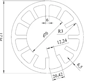
As mentioned above, ALM application in the magnetic cores of generators minimizes losses in the magnetic cores. In order to evaluate the effectiveness of the ALM application in the magnetic cores of generators, two identical magnetic cores have been were made, the only difference of which is the magnetic core material. The dimensions of magnetic cores were calculated with analytical methods. The active length of the magnetic cores is 70 mm. The geometric dimensions of the magnetic cores in the front view are shown in Fig. 1.
Figure 1. The geometric dimensions of the magnetic cores.
The materials used in the magnetic cores of generators are elaborated below.
One of the magnetic cores is made of 1SR ALM manufactured by PJSC “Ashinsky Metallurgical Plant”. Fig. 2 shows the 1SR ALM magnetization curve.
(b) (a)
Figure 2. Dynamic hysteresis loops for 1SR ALM at (a) a temperature of 80◦C and a frequency of 2000 Hz (induction 0.4561 T) and (b) at a temperature of 80◦C and a frequency of 400 Hz (induction 0.3595 T).
or 1SR) are difficult to process when making a large magnetic core. Cobalt containing ALMs are also highly brittle and more prone to crumbling than cobalt free ALMs. Our research team aimed to create magnetic cores with an outer diameter up to 121 mm, which use cobalt containing ALMs [7].
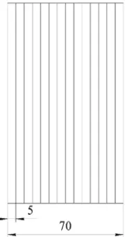
The ALM magnetic core manufacturing technology is elaborated below. The ALM generator magnetic core is made up of 12 cores. Each core is formed from ALM tape, which is wound on a cylindrical rigging. It is important that the number of individual formed cores is equal to the number of slots in the magnetic core. The shape of each individual core is made triangular in order to ensure the most efficient use of the material. The triangular shape of each core is achieved by installing cylindrical coils obtained from the ALM tape in a rigging with triangular cutouts. After that, all individual cores are impregnated. As a result, the cores acquire the necessary shape and hardness. Individual triangular-shaped cores are then subjected to joint impregnation and gluing, which makes it possible to form a generator magnetic core from them. The generator magnetic core made with our technology provides the required mechanical strength and magnetic properties. The ALM tape width used in the manufacture of magnetic cores with our technology is 50 mm. Therefore, the minimum core length is 50 mm, which makes the eddy current losses significant. The magnetic core is formed from individual stacks to reduce eddy current and hysteresis losses. The individual stacks are isolated from each other. Each individual stack is not more than 5 mm thick. The stacks are formed by mechanically cutting a triangular core 50 mm long into 10 cores 5 mm long. Thus, the ALM generator magnetic core is laminated both axially and radially. The ALM generator magnetic core disadvantages are complexity and high cost of its manufacture, as well as fragility and crumbling as compared with an electrotechnical steel magnetic core. A side view of the ALM generator magnetic core is shown in Fig. 3.
Figure 3. Side view of the ALM generator magnetic core.
The second magnetic core is made of grade 2421 silicon steel 0.18 mm thick. The studies were performed for materials produced in the Russian Federation. The silicon electrotechnical steel with the minimum sheet thickness produced in the Russian Federation was chosen. Silicon steels with a sheet thickness of 0.1 and 0.05 mm are known in the world industry. However, steels with a sheet thickness of 0.1 and 0.05 mm were not available to our research team. A comparison of the silicon steels with a sheet thickness of 0.1 and 0.05 mm and the electrotechnical steel 2421 used by our research team, as well as the used 1SR ALM, is given in Table 1.
One can see in Table 1 that steel 2421 is inferior in specific characteristics to its foreign counterparts with a smaller sheet thickness. The data of Table 1 enable the comparison of experimental research results for ALM magnetic cores and those for the magnetics cores made of electrotechnical steel 2421 and materials with a smaller sheet thickness. The magnetization curves for electrotechnical steel 2421 and 1SR ALM are shown in Fig. 4 on the same scale.
Table 1. Properties of 1SR ALM and steel 2421 for a magnetic core.
Alloy properties 1SR ALM steel 2421, 0.18 mm 10JNEX900, 0.1 mm Vacodur 50, 0.1 mm
Saturation induction B, T 1.6 1.8 2 2.3
Specific loss W/kg, with
induction of 1 T and 400 Hz 2 12.5 8 10–12
Magnetic field strength
with induction 1 T, A/m 200–210 2500 80–85 3–5
Density γ, g/cm3 7.3 7.6 7.49 8.12
tooth parameters) as the ALM generator magnetic core. The electrotechnical steel magnetic core is laminated only axially. The second generator magnetic core is made from electrotechnical steel sheets 0.18 mm thick. High-temperature glue VS-10T was used for gluing of the electrotechnical steel sheets. Electrotechnical steel sheets were obtained by erosion cutting.
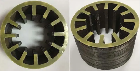
The ALM generator magnetic core is shown in Fig. 5. The electrotechnical steel generator magnetic core is shown in Fig. 6.
Figure 4. 1SR ALM and electrotechnical steel
2421 magnetization curves atf = 400 Hz. Figure 5. 1SR ALM generator magnetic core.
Figure 7. The generator winding frontal parts overhangs.
The winding of the generators is fractional toothed. The fractional toothed winding is used to minimize the frontal parts overhang. The number of slots per pole and phase is 2/5. The generator winding frontal parts overhangs are shown in Fig. 7.
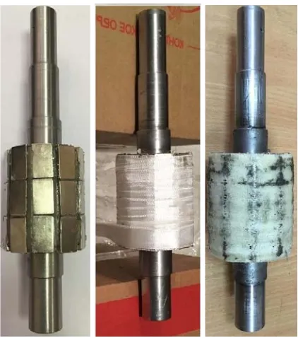
NdFeB N38M permanent magnets were used as the permanent magnets of the rotor. This choice of the permanent magnets is determined by the designed generator being operated at an ambient temperature of not more than 40◦C. The rotor magnets are segmented axially to reduce hysteresis and eddy currents losses in the permanent magnets. The segment length is 25 mm. The bandage is made of fiberglass impregnated with epoxy glue. The band is 2 mm thick. The generator rotor assembly is shown in Fig. 8.
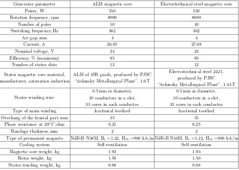
The main characteristics of generators with 1SR ALM and electrotechnical steel 2421 magnetic cores are given in Table 2.
Table 2. Geometric dimensions and parameters of generators.
Generator parameter ALM magnetic core Electrotechnical steel magnetic core
Power, W 550 550
Rotation frequency, rpm 8000 8000
Number of poles 10 10
Switching frequency, Hz 362 362
Air gap, mm 4 4
Current, A 26,85 27,08
Nominal voltage, V 24 24
Efficiency, % (minimum) 95 95
Number of stator slots 12 12
Stator magnetic core material, manufacturer, saturation induction
ALM of 1SR grade, produced by PJSC “Ashinsky Metallurgical Plant”, 1.6 T
Electrotechnical steel 2421, produced by PJSC
“Ashinsky Metallurgical Plant”, 1.44 T
Stator winding wire
0.5 mm in diameter, 10 conductors in a slot, 33 cores in each conductor
0.5 mm in diameter, 10 conductors in a slot, 33 cores in each conductor
Type of main winding fractional toothed fractional toothed
Overhang of the frontal part, mm 35 35
Phase resistance at 20◦C ohm 0,25 0,25
Bandage thickness, mm 2 2
Type of permanent magnets NdFeB N38M, Br=1.22, Hcb=900 kA/m NdFeB N38M, Br=1.22, Hcb=900 kA/m
Cooling system Self-ventilation Self-ventilation
Magnetic core weight, kg 1.93 1.93
Rotor weight, kg 1.50 1.50
Stator winding weight, kg 0.68 0.68
The manufacturing technologies of multi-slot magnetic cores from ALM and electrotechnical steel, as well as the properties, characteristics and features of these materials, were described in previous works of our research team. In this paper, manufacturing technology and material properties are provided with the goal of providing the ability to analyze the obtained results of our studies.
3. COMPUTER SIMULATION
Not all the processes that take place in the generator magnetic cores can be analyzed on the basis of analytical calculation data and on the basis of experimental data. Therefore, computer simulation of the generators with ALM and electrotechnical steel magnetic cores is carried out using finite element methods. For the generators computer simulation Ansys Maxwell software was used. When modelling, the main task is to obtain the pattern of the magnetic field distribution in the magnetic cores and to determine the losses in the permanent magnets. In the computer simulation of the generator with an ALM magnetic core, it is important to consider the technological gaps in the ALM magnetic core. Also, the ALM generator magnetic core contains an uneven air gap due to the technology of its manufacture. The air gap is maximum in the center of the stator teeth and minimal at the edges of the stator teeth. The air gap along the edges of the stator teeth does not change for more than 0.5 mm. The computer simulation does not take into account the axial stacking of AMM and electrotechnical steel magnetic cores. Obtained results of generators computer simulation are shown in Fig. 9–Fig. 12.
with an ALM magnetic core are significantly lower than that for a generator with an electrotechnical steel magnetic core.
The computer simulation results were then verified by comparing the computer simulation data with experimental data.
(b) (a)
Figure 9. Magnetic field distribution (a) in the electrotechnical steel magnetic core and (b) in the ALM magnetic core.
(a) (b)
Figure 10. Losses in permanent magnets (a) in the electrotechnical steel magnetic core and (b) in the ALM magnetic core.
(a) (b)
(a) (b)
Figure 12. Voltage in the generator windings at 2000 rpm (a) in the electrotechnical steel magnetic core and (b) in the ALM magnetic core.
4. EXPERIMENTAL STUDIES
Two identical generator experimental models of generators were made to conduct the experimental studies. The models differed only in the material of the magnetic core. The parameters of the experimental models are given in Table 3. The experimental models are shown in Fig. 13.
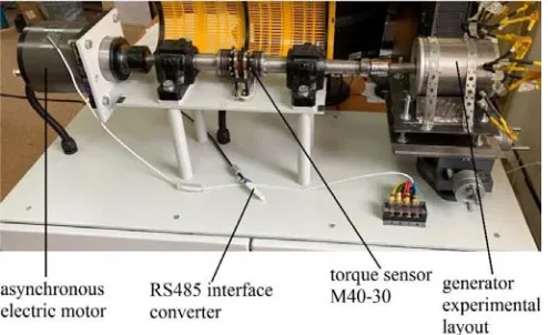
Then the generator experimental models were tested on a special bench. The bench is shown in Fig. 14.
The bench design is described below. The bench has an asynchronous electric motor capable of accelerating to 12,000 rpm at a supply current frequency of 400 Hz. The asynchronous electric motor is controlled by a frequency converter. There is an M40-30 torque sensor, manufactured by LLC
(a) (b)
Figure 13. Generator experimental models (a) with an ALM magnetic core and (b) with an electrotechnical steel magnetic core.
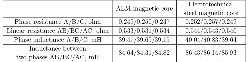
Table 3. Linear and phase resistances and inductances of the windings in the generator experimental models.
ALM magnetic core Electrotechnical steel magnetic core Phase resistance A/B/C, ohm 0.249/0.250/0.247 0.252/0.257/0.249 Linear resistance AB/BC/AC, ohm 0.533/0.531/0.534 0.544/0.543/0.540 Phase inductance A/B/C, mH 39.47/39.69/39.15 40.04/40.83/39.64
Inductance between
Figure 14. Bench for generator experimental studies.
“TILKOM” and the generator experimental model on the same shaft with the asynchronous electric motor. The asynchronous electric motor rotates the generator experimental model. The parameters of the M40-30 torque sensor are shown in Table 4.
Table 4. Parameters of the M40-30 torque sensor manufactured by LLC “TILKOM”.
M40-30 torque sensor parameter Value Nominal range of torque measurement, Nm −30. . .30
Rotation frequency 2000 . . . 20000
Accuracy class 0.2
Ambient temperature range,◦C 0. . . +60 Power consumption, W (not more) 5
Supply voltage, V 12 . . . 30
Interface RS485
The number of measurements per second 5000
A T46 decoder is installed after the torque sensor M40-30. The torque sensor is connected to a personal computer by an RS485 interface converter. Special software is installed on the PC, which allows getting numerical values of the sensor readings and visualizes the measurement results. The Sensor software version 4.1.3.0 developed by LLC “TILKOM” is installed on the PC to work with the M40-30 torque sensor. The M40-30 torque sensor measures the torque on the bench shaft, the power on the bench shaft, and the rotation frequency of the bench shaft. The measurement error is not more than±0.2%.
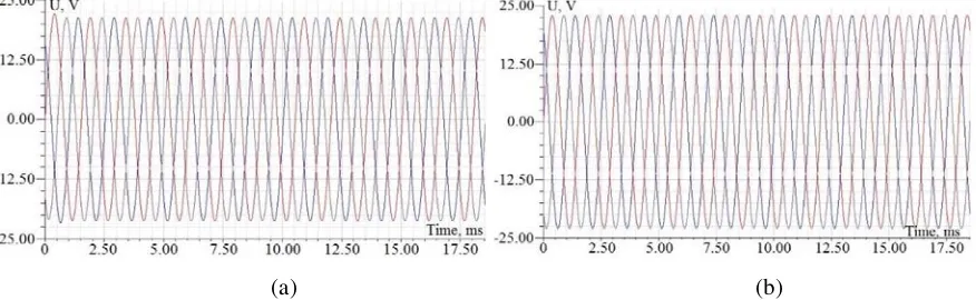
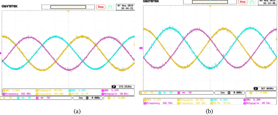
The first stage of the experimental studies is to obtain EMF waveforms of the generator experimental models. The EMF in the windings of the generator experimental models has a sinusoidal shape. The EMF curves of the generator experimental models under study are presented in Fig. 15.
The results of the computer simulation deviate from the results of the experimental studies by no more than 7.1% for the electrotechnical steel magnetic core and no more than 8.2% for the ALM magnetic core, which indicates the efficacy of the created computer models of the generators.
Next, the experimental models of generators were investigated while idling. Fig. 16 shows the dependence of the shaft torque on the rotation frequency. Fig. 17 shows the dependence of the generator mechanical power on the rotation frequency. Fig. 18 shows the dependence of the phase output voltage on the rotation frequency.
(a) (b)
Figure 15. EMF in the windings of the generator experimental models at 2000 rpm with (a) an ALM magnetic core and (b) an electrotechnical steel magnetic core.
Figure 16. The dependence of the shaft torque on the rotation frequency.
Figure 17. The dependence of the mechanical power on the rotation frequency.
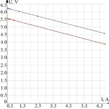
Figure 19. The dependence of the voltage on the load current.
It is apparent that the actual characteristics of the generator with an ALM magnetic core are lower. The angle of the external characteristics of both generators is the same. The lower characteristics of the generator with an ALM magnetic core may be attributable to its technological specifics. Firstly, the ALM magnetic core has significant technological gaps due to its manufacturing technology. Secondly, the generator with an ALM magnetic core has an uneven air gap, which is also attributable to the manufacturing technology of the ALM stator. The ending of the ALM magnetic core tooth is V-shaped. Accordingly, the air gap is maximal at the center of the tooth, and the air gap is minimal at the edges of the tooth. The impact that the irregularity in the air gap of the ALM magnetic core has on the generator parameters is also confirmed by the created finite element mathematical model. Therefore, it is advisable to take into account the technological features, the irregularity in the air gap of the ALM magnetic core in particular, during design and simulation. In addition, one of the phase teeth was damaged when assembling the experimental model of the generator with an ALM magnetic core, which could also affect the lower characteristics of the generator with an ALM magnetic core as compared to the generator with an electrotechnical steel magnetic core. It was found in previous works of our research team that the performance of generators with ALM magnetic cores is better than that of generators with electrotechnical steel magnetic cores.
5. RESULTS AND CONCLUSIONS
This work studies generators with a rotation frequency of 8000 rpm with magnetic cores from ALM and electrotechnical steel. The results of the computer simulation showed that application of ALM as the material of the generator magnetic core could reduce core losses significantly. However, the studied generator with an ALM magnetic core has lower characteristics than a generator with an electrotechnical steel magnetic core. This is attributable to technological gaps in the ALM generator magnetic core, an uneven air gap for the generator with an ALM magnetic core, and a design defect in the ALM generator magnetic core resulting from the assembly of the generator experimental model with the ALM magnetic core. Therefore, when creating multi-slot generators with ALM magnetic cores, the future work purposed will be to obtain an even air gap by changing the manufacturing technology of ALM multi-slot magnetic cores, and further efforts will be aimed at reducing the technological gaps in ALM magnetic cores.
ACKNOWLEDGMENT
REFERENCES
1. Wang, Z., et al., “Development of a permanent magnet motor utilizing amorphous wound cores,”
IEEE Trans. Magn., Vol. 46, No. 2, 570–573, Feb. 2010.
2. Wang, Z., et al., “Development of an axial gap motor with amorphous metal cores,” IEEE Trans. Ind. Appl., Vol. 47, No. 3, 1293–1299, May/Jun. 2011.
3. Patent DE 102012207508 A1 Stator f¨ur eine elektrische Maschine und Verfahren zum Herstellen eines Stators f¨ur eine elektrische Maschine/Manfred R¨uhrig, applicant Siemens Aktiengesellschaft. 07.05.2012.
4. Ismagilov, F. R., V. E. Vavilov, D. V. Gusakov, and O. Jing, “High-speed generator with tooth-coil winding, permanent magnets and new design of a stator magnetic core made from amorphous alloy,” 2018 25th International Workshop on Electric Drives: Optimization in Control of Electric Drives, DOI: 10.1109/IWED.2018.8321395, 2018.
5. Ismagilov, F. R., I. K. Khayrullin, V. Y. Vavilov, V. I. Bekuzin, and V. V. Ayguzina, “Minimization of energy losses in ultra-high-speed electrical rotating machines,” Elektrotehniski Vestnik/Electrotechnical Review, Vol. 84, No. 1–2, 56–60, 2017.
6. Ismagilov, F., V. Vavilov, V. Bekuzin, V. Ayguzina, N. Uzhegov, “Multidisciplinary design of ultra-high speed electric machines,” IEEE Transactions on Energy Conversion, DOI: 10.1109/TEC.2018.2803146, 2018.