A Novel Binary Butterfly Mating Optimization Algorithm with
Subarray Strategy for Thinning of Large Antenna Array
Hua-Ning Wu, Chao Liu, Bin Li*, and Xu Xie
Abstract—This paper presents a novel binary algorithm named as binary butterfly mating algorithm (BBMO) combined with subarray strategy for thinning of antenna array. The proposed algorithm has been adapted from a recently developed nature inspired optimization, butterfly mating optimization (BMO). The subarray strategy is dividing the linear array into two parts, one part with a fixed number of element turned on in the middle of array and the rest elements on the edge of array composing another subarray. In order to reduce the complexity of the thinning process, BBMO algorithm is used to optimize the element on the edge of an array. The proposed BBMO with subarray strategy is used to synthesize a linear sparse antenna array in order to reduce maximum sidelobe level and at the same time keeping the percentage of thinning equal to or more than the desired level. To evaluate the performance of the proposed thinning method, a linear array with 100 elements is optimized by BBMO algorithm without and with subarray strategy. And we discuss the impact of number of fixed elements on thinning results. The novel method BBMO with subarray strategy gives reduced SLL as compared to the results available in literature of ant colony algorithm, genetic algorithm, binary differential evolution algorithm, chaotic binary particle swarm optimization, and improved binary invasive weed optimization algorithm. Moreover, the convergence rate of BBMO with subarray strategy is faster than BBMO without subarray strategy and the other methods.
1. INTRODUCTION
Thinning of antenna arrays involves the removal (turning off) of some elements in the antenna array so as to maintain radiation properties similar to that of the fully populated array, but using a lower number of elements. An element connected to the feed network is ‘turned on’, and an element connected to a matched load is ‘turned off’ [1, 2]. The main motivation to use thinning is the reduction in cost, weight and power consumption. And thinned arrays present the advantage of ease of realization, as different elements usually lie on a regular grid, operate with equal amplitude, and are directly connected to the amplifiers [3]. Hence, the synthesis of arrays using thinning is under active research by many groups. Many stochastic, probabilistic or evolutionary optimization approaches, such as the simulated annealing, genetic algorithm [1], ant colony optimization [4], different evolutions [5], particle swarm optimization algorithm [6] and invasive weed optimization [7] have been used and shown to be effective for the synthesis of thinned arrays. Some other approaches [8–10] have also been proposed.
Although these methods have achieved good results, when the array size becomes very large, the search process is also very time-consuming to get good results. How to reduce the reaction time of a large-scale sparse array system and at the same time get better side lobe level is a question. To solve this problem can start from two ways. One way is to find a fast new algorithm with good optimization characteristic, or improve the optimization speed of some already existing algorithms and does not deteriorate the accuracy of optimization. The other way is to adopt some strategies to simplify the
Received 18 July 2017, Accepted 14 September 2017, Scheduled 18 September 2017 * Corresponding author: Bin Li ([email protected]).
optimization problems. In this paper, a new fast optimization method named binary Butterfly Mating Optimization combined with a subarray strategy is proposed to synthesize a large linear antenna array. Butterfly Mating Optimization (BMO) is a novel swarm intelligent algorithm, based on the mating phenomena occurring in butterflies [11]. The butterflies use UV (Ultraviolet, one kind of iridescence) reflectance and absorbance mechanism for mating. In BMO, each butterfly can choose its mate anywhere in the search space adaptively in each iteration, and this mate is defined as a local mate (l-mate). This adaptive selection process of l-mate plays a key role in the BMO algorithm. The BMO algorithm starts with well randomly dispersive butterflies in the search space. Then each butterfly updates its UV, distributes to and accesses UV from all the others, chooses l-mate and moves towards that. For a binary solution, the basic BMO algorithm working in the continuous domain must be modified. Hence, a new binary BMO (BBMO) is proposed which provides the solution in binary search space with 0 or 1 values. In BBMO, the hamming distance is proposed to represent the distance between two butterflies, and the position of each butterfly is updated in the form of probability.
Subarrays are made by dividing a whole antenna array into two or more smaller arrays. In this paper, we divide the linear array into two parts, one part with a fixed number of element turned on and the rest elements on the edge of the array composing another subarray. In order to reduce the complexity of the thinning process, BBMO algorithm is used to optimize the element on the edge of the array.
The rest of the paper is organized as follows. A formulation of the thinned array pattern synthesis as an optimization task is discussed in Section 2. Section 3 gives a comprehensive overview of the proposed BBMO algorithm. Section 4 presents the simulation results, and in Section 5 conclusions are presented.
2. THINNED ARRAY
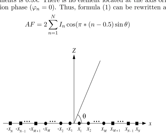
According to the structure shown in Figure 1, where there are 2N isotropic elements placed symmetrically along thex-axis, and the array factorAF at anθ angle inXZ plane for a linear antenna array can be expressed as [4, 6]:
AF =
n=N
n=−N
Anexp
j∗
2π
λ xn∗sinθ+ϕn
(1)
wherexn,In and ϕn are the position, excitation amplitude and phase of the nth element, respectively.
In the thinned array,Im is 0 if the status of themth element is ‘off’, andIm is 1 if it is ‘on’. In our case,
the distance between elements is 0.5λ. There is no element located at the axis origin, and all elements have the uniform excitation phase (ϕn= 0). Thus, formula (1) can be rewritten as [4, 6]
AF = 2
N
n=1
Incos(π∗(n−0.5) sinθ) (2)
Z
x
...
...
...
...
θ-x -xN N - 1 -xM + 1 -xM -x -x2 1 x1 x2 xM xM + 1 xN - 1 xN
In order to control the array pattern as desired, different parameters of the far-field pattern must be considered in the fitness function. The first and most important parameter is the normalized maximum side-lobe level (MSL) that is desired to be as low as possible. The normalized MSL of the antenna array can be given by formula (3).
FMSL(I) = max ∀θ∈R
20 logAF(I, θ)
AFmax
(3)
where R represents the side-lobe region excluding the main beam. In this paper, Equation (4) is used as the objective function to suppress MSL.
f(I) =FMSL(I) (4)
We need to find which array elements should be enabled or disabled (In = 1 or In = 0) to get the desired radiation pattern characteristics. Hence, the problem of thinned array synthesis can be formulated as the following 0–1 integer optimization problem.
3. BUTTERFLY MATING OPTIMIZATION ALGORITHM
Butterfly Mating Optimization (BMO) [11] is a recently developed meta-heuristic algorithm that mimics the mating behavior of butterflies. BMO algorithm utilizes the principle of bionics, simulating the butterfly which confirms the position of a local mate butterfly in the mating process by using ultraviolet intensity reflected and absorbed by itself [11]. Male butterflies use color and scent during mating to hunt for mates. Specifically speaking, the eye spot on the forewings of the male butterflies can reflect UV. When the receiver of female butterfly perceives the high frequency color from male butterfly, if the female butterfly absorbs the UV, it means to accept mating; if the female butterfly reflects UV, it means refusal in mating, and the male butterfly will leave.
3.1. Basic Principle of BMO Algorithm
In the iterative process, BMO algorithm assumes that there is no individual difference between the male and female butterflies, and both can absorb and reflect UV. Therefore, the kind of butterfly is defined as an element butterfly in this algorithm. The element butterfly is randomly distributed in the search domain, and in each iteration the element butterfly changes its UV value according to its adaptability and assign its UV value according to its distance from other element butterflies.
BMO algorithm is divided into four stages: UV value update stage, UV value allocation stage, local mate positioning stage and movement stage.
3.1.1. UV Value Update
The UV value of each element butterfly is updated on a certain scale based on the existing position
U Vi(t) = max{0, b1×U Vi(t−1) +b2×f(t)} (5) U Vi(t) stands for the UV value of the ith butterfly when the number of iterations is t. b1 and b2 stand
for the weight factor. If the update of UV value depends on the UV value U Vi(t−1) of the t−1th generation, thenb1≥1, 0≤b2 <1; on the contrary, if the update of UV value depends on the adaptive
valuef(t) of the current generation of element butterfly, then b2 ≥1, 0≤b1 <1.
3.1.2. UV Value Allocation Stage
In the UV value allocation stage, each element butterfly will assign its UV value according to its distance from other butterflies, and the assigned UV value in close distance is large, while the assigned UV value in far distance is small.
U Vi→j =U Vi× d
−1
ij
k
Among them,U Vi→j stands for U V value assigned by theith butterfly to thejth butterfly;dij denotes the Euclidean distance between theith butterfly and jth butterfly; dik denotes the Euclidean distance
between the butterfly and any other kth butterfly.
3.1.3. Local Mate Selection Stage
The local mate selection stage is divided into two steps. The first step is to arrange all the other butterflies in descending order according to the UV value assigned by the ith butterfly to the other butterflies. The second step is to compare U Vi with the U Vj which is from the UV value of the jth butterfly one by one according to the order in the first step. If it is necessary to choose the maximum value of fitness function, the maximum U Vj greater than U Vi should be selected; if it is necessary to choose the minimum value of fitness function, then the corresponding jth butterfly is the local mate.
3.1.4. Movement Stage
Based on the position of its local mate, each element butterfly will move toward it according to formula (7)
xi(t+ 1) =xi(t) + step× xl-mate(t)−xi(t) xl-mate(t)−xi(t)
(7)
wherein xi(t) indicates the position of the butterfly in the tth generation, and xl-mate stands for the
l-mate position of theith butterfly in thetth generation. Step represents the iteration step, which is a fixed constant.
3.2. Binary BMO Algorithm
The BMO algorithm is used to solve the problems of continuous variables. When it comes to the thinned array, the variables representing the on/off status of the units are binary. Inspired by the basic BMO algorithm, binary BMO is proposed for binary optimization problems. The modification of BMO is shown as follows.
3.2.1. Distance Compute
Instead of the Euclidean distance adopted in the movement stage of BMO, Hamming distance is proposed to compute the distance between theith andjth butterflies. The Hamming distance between the two butterflies is the number of locations where one has a ‘0’, and the other has a ‘1’. It can be expressed by:
hm dij(t) =(mod(xi(t) +xj(t),2)) (8)
3.2.2. Location Update
The location of every butterfly is composed of N binary variables. In the location update process, the moving step is ignored, and the position ofith butterfly is updated based upon the probability defined by the Hamming distance between xi(t) andxl-mate(t).
pr = 0.9×
(mod(xi(t) +xl-mate(t),2))
j
(mod(xj(t) +xl-mate(t),2))
+ 0.1 (9)
xi,k(t) =
mod(xi,k(t−1) + 1,2) pr≤ξ(k)
xi,k(t−1) pr > ξ(k) (10)
where xi,k(t) is the location of dimension k of the ith butterfly at iteration t; ξ(k) is the parameter
4. SIMULATION RESULTS
In this section, we use two thinned array cases to evaluate the search ability of the proposed method. All simulations are conducted in a Windows 7 Professional OS environment using 2-core processors with Intel Xeon (R), 2.13 GHz, 1.99 GB RAM, and the codes are implemented in Matlab 7.10.
4.1. Case One
The first case discussed here is to thin a linear array with 100 elements symmetrically spaced 0.5λapart along thex-axis with its center at the origin in order to generate a broadside symmetric pattern [1, 4, 6]. In [1], Haupt designs the same array using GA. In [4], Quevedo-Teruel and Rajo-Iglesias utilize the ACO algorithm to the pattern synthesis of linear thinned array. Wang et al. use chaotic binary PSO algorithm in the linear thinned array design and obtain a better result than the other algorithms [6]. Liu and Wu proposed an improved binary invasive weed optimization (IBIWO) and utilize it to design the thinned array with lower MSL [7].
In this work, BBMO is utilized to design the thinned array with lower MSL. Because of the randomness nature, all the experiments have been run 100 times with 300 iterations independently. The stopping criterion of each run is to complete the number of iterations. The number of butterflies is 50. The best and average results are presented in this section.
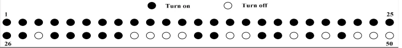
According to the symmetrical structure shown in Figure 1, only 50 elements are optimized. Figure 2 shows the best pattern obtained by the BBMO, and the result is compared with the fully populated array in which all elements are turned on. From Figure 2, we notice that the MSL with the full 100-element linear array (all 100-elements are turned on) is −13.73 dB, and the MSL is lowered to −21.18 dB after thinning by BBMO. Figure 3 gives the element status of the best thinned array with minimum MSL obtained by BBMO algorithm. As shown in Figure 3, the number of turn-off elements is 24.
Figure 2. Radiation pattern compared with the initial value.
0 10 20 30 40 50 60 70 80 90 -40
-35 -30 -25 -20 -15 -10 -5 0
N
o
rm
al
iz
ed A
F
(dB)
ACO BBMO
θ (deg)
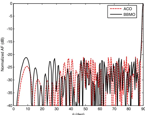
Figure 4. Comparisons of 100-elements thinned linear array pattern obtained by BBMO and ACO algorithm.
(a) (b)
Figure 5. Comparisons of best results obtained by BBMO and other algorithms. (a) Percentage of thinning (%). (b) Absolute value of MSL (dB).
To further verify the performance of the BBMO, it is compared with the GA [1], ACO [4], BDE [5], BPSO [6], CBPSO [6] and IBIWO [7]. The obtained array patterns using ACO and BBMO are presented in Figure 4. Figure 5 represents the comparisons of the results obtained by the BBMO algorithm and the other six algorithms. The results used for comparison are given by [4, 6]. From Figure 5(a) we can clearly know that the percentage of thinning obtained by the BBMO is 24%, which is more than that of 20% in [4, 6] and 22% in [1, 5, 7], except that of 24% obtained by CBPSO in [6]. As shown in Figure 5(b), the absolution value of MSL obtained by BBMO is larger than that of other algorithms, except for CBPSO and IBIWO.
Figure 6 shows the convergence curve of BBMO to obtain the best results. From Figure 6, we can clearly see that the speed of BBMO is very fast, and the convergence iterations up to the best fitness are 76. To evaluate the efficiency and reliability of the proposed algorithms, the BBMO algorithm is further compared with these before mentioned algorithms in terms of average convergence speed and average maximum SLL. The average values are calculated from the 100 times optimization of each algorithm.
0 50 100 150 200 250 300 0.025
0.03 0.035 0.04 0.045 0.05 0.055 0.06
Iteration
Fit
n
e
s
s
Figure 6. Convergence curve of BBMO to achieve the best results.
Table 1. Comparisons of the simulation results.
Simulation results Average maximum|MSL| Average convergence iterations
GA 19.2 164
ACO 19.1 203
BDE 18.5 193
BPSO 14.6 236
CBPSO 20 181
IBIWO 22.04 200
BBMO 19.8 62
4.2. Case Two
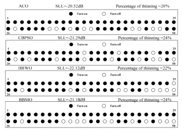
In case one, BBMO algorithm is utilized to thin a linear array with 100 elements and obtains good results. The best element status obtained by ACO, CBPSO, IBIWO and BBMO are shown in Figure 7. From Figure 7 we can know that the status of 25 elements in the front of the thinned linear array optimized by ACO and BBMO are ‘on’. The numbers of turn-off elements in the front of the thinned linear array obtained by CBPSO and IBIWO are 3 and 1. The difference of the percentage of thinning achieved by these algorithms is small, and the thinned elements are almost located on the back 25 elements of the linear array. The values of MSL obtained by these algorithms are very different. The best MSL is−22.12 dB obtained by IBIWO algorithm, which is 1.6 dB lower than ACO algorithm. From the above discussion we may draw a conclusion that the states of elements in front of the array have a litter impact on the optimization results, and the MSL and percentage of thinning of the whole array may be determined by the status of the elements in the back of the array. So we divide the right side of the linear array into two subarrays in Figure 1. The M elements in the front of the linear array compose one subarray named FLA, and the N-M elements in the edge of the linear array compose another subarray named BLA.
BBMO optimized antenna array is shown in Figure 9. The maximum SLL achieved by BBMO with subarray strategy is −22.60 dB, which is 1.42 dB lower than case one and also lower than all other algorithms.
The convergence characteristics of BBMO with and without fixed element are shown in Figure 10.
Turn on Turn off
1 25
26 50
Turn on Turn off
1 25
26 50
Turn on Turn off
1 25
26 50
Turn on Turn off
1 25
26 50
Figure 7. The elements status obtained by ACO, CBPSO, IBIWO, BBMO.
Figure 8. The elements status obtained by BBMO with fixed 25 elements turned on.
0 10 20 30 40 50 60 70 80 90
θ (deg) 0
-5
-10
-15
-20
-25
-30
-35
-40
-45
Normalized AF (dB)
fully populated array
BBMO without sub-array strategy BBMO with sub-array strategy
Figure 9. Radiation pattern of fully populated array, BBMO with and without sub-strategy.
BBMO without sub-array strategy BBMO with sub-array strategy
0 50 100 150 200 250 300
Iterations 0.055
0.05
0.045
0.04
0.035
0.03
0.025
0.02
0.015
0.01
Fitness
0 10 20 30 40 50 60 70 80 90 00 5 10 15 20 25 30 35 10
20 30 40 50 60 70
M
(a) (b)
θ (deg) 0
-5
-10
-15
-20
-25
-30
-35
-40
Normalized AF (dB)
M=0
M=15 M=35
Percentage of thinning (%) Absolution of MSL (dB) Iterations of convergence
Figure 11. (a) The best patterns obtained by BBMO under M = 0,15,35. (b) Results obtained by BBMO with sub-strategy under different numbers of elements in FLA atM = 0,5,10,15,20,25,30,35.
Table 2. Comparisons of the simulation results by BBMO with sub-strategy under number of elements in FLA.
M Thinning
percentage (%)
MSL (dB)
Convergence iterations
Average
convergence iterations
average MSL (dB)
0 24 −21.19 69 62 −19.8
5 18 −21.93 64 49 −20.59
10 20 −21.58 42 41 −20.85
15 18 −23.03 25 36 −21.25
20 18 −22.54 38 30 −21.65
25 20 −22.6 38 27 −20.73
30 18 −22.75 17 10 −21.92
35 18 −22.84 6 6 −22.12
From Figure 10 we can see that the convergence iterations of BBMO with fixed element are 38, and the convergence speed is faster than BBMO without sub-strategy.
As discussed above, we use BBMO algorithm which gets better results with sub-strategy when the number of elements in FLA is 25. Then, we will study how the M elements in FLA impact the optimization results. In the view of percentage of thinning, the value of M should be smaller than 35 and chosen in the set R, R={0,5,10,15,20,25,30,35}. BBMO is run 100 times, each time with 300 iterations.
Figure 11(a) shows the best pattern optimized by BBMO algorithm under different M. From Figure 11(a) we can know that the widths of main beams are nearly the same under different M, and the values of maximum SLL are different. In order to further understand how the value of M impact the optimization results, Figure 11(b) gives the curves of the maximum SLL, percentage of thinning, convergence iterations versus the values ofM which varies from 0 to 35. The values of maximum SLL of the best thinned array obtained by BBMO are−21.18 dB,−21.93 dB,−21.58 dB,−23.03 dB,−22.54 dB, −22.6 dB,−22.75 dB, and −22.84 dB, respectively, whenM = 0,5,10,15,20,25,30,35. Compared with
M = 0, the BBMO algorithm achieves lower maximum SLL when M > 0, and the lowest maximum SLL is −23.03 dB, which is lower by nearly 2 dB. The percentages of thinning of the best thinned array obtained by BBMO are 24%, 18%, 20%, 18%, 18%, 20%, 18%, and 18%, respectively, when
largest difference is 6%. The largest difference of percentage of thinning between different M(M >0) is 2%. Table 2 shows the comparisons of the simulation results by BBMO with sub-strategy under different numbers of elements in FLA.
From the above analysis, we can know that the subarray strategy can not only improve the convergence speed of the algorithm, but also get lower SLL. For a large array system, it not only can reduce the complexity of the system and improve the response time of the system, but also is able to better reduce the effects of noise on the system.
5. CONCLUSIONS
A novel binary algorithm named as binary butterfly mating algorithm combined with subarray strategy is proposed for thinning of an antenna array, in order to reduce maximum SLL and at the same time keeping the percentage of thinning equal to or more than the desired level. To evaluate the performance of the proposed thinning method, a linear array with 100 elements is optimized by BBMO algorithm without and with subarray strategy. The simulation results show that the proposed method is very effective for linear array thinning. Future work includes adapting BBMO for solving planar or circular antenna array.
ACKNOWLEDGMENT
This work was supported in part by the Naval University of Engineering fund, under Grant No. HGDYDJJ13008.
REFERENCES
1. Haupt, R. L., “Thinned arrays using genetic algorithms,”IEEE Trans. Antennas and Propagation, Vol. 42, No. 7, 993–999, July 1994.
2. Wang, X.-K., Y.-C. Jiao, Y. Liu, and Y. Y. Tan, “Synthesis of large planar thinned arrays using IWO-IFT algorithm,” Progress In Electromagnetics Research, Vol. 136, 29–42, 2013.
3. Bucci, O. M., T. Isernia, and A. F. Morabito, “A deterministic approach to the synthesis of pencil beams through planar thinned array,” Progress In Electromagnetics Research, Vol. 101, 217–230, 2010.
4. Quevedo-Teruel, O. S. and E. Rajo-Iglesias, “Ant colony optimization in thinned array synthesis with minimum sidelobe level,” IEEE Antennas and Wireless Propagation Letters, Vol. 5, No. 1, 349–352, February 2006.
5. Zhang, L., Y. C. Jiao, Z. B. Weng, and F. S. Zhang, “Design of planar thinned arrays using a boolean differential evolution algorithm,” IET Microwaves, Antennas and Propagation, Vol. 4, No. 12, 2172–2178, December 2010.
6. Wang, W.-B., Q. Feng, and D. Liu, “Synthesis of thinned linear and planar antenna arrays using binary PSO algorithm,”Progress In Electromagnetics Research, Vol. 127, 371–387, 2012.
7. Liu, C. and H. Wu, “Synthesis of thinned array with side lobe levels reduction using improved binary invasive weed optimization,”Progress In Electromagnetics Research M, Vol. 37, 21–30, 2014. 8. Oliveri, G., M. Donelli, and A. Massa, “Linear array thinning exploiting almost difference sets,”
IEEE Trans. Antennas and Propagation, Vol. 57, No. 12, 3800–3812, December 2009.
9. Rocca, P., “Large array thinning by means of deterministic binary sequences,” IEEE Trans.
Antennas and Wireless Propagation Letters, Vol. 10, No. 4, 334–337, October 2011.
10. Jayasinghe, J. W., J. Anguera, and D. N. Uduwawala, “A high-directivity microstrip patch antenna design by using genetic algorithm optimization,”Progress In Electromagnetics Research C, Vol. 37, 131–144, 2013