Design and Analysis of Novel Bearingless Permanent Magnet
Synchronous Motor for Flywheel Energy Storage System
Huangqiu Zhu and Ronghua Lu*
Abstract—To effectively simplify system structure and improve power density and efficiency, a design for a motor/generator suitable for flywheel energy storage system (FESS) is proposed. The machine is an outer-rotor and coreless-stator-type bearingless permanent magnet synchronous motor (BPMSM) with a Halbach array. Firstly, the operation principle of the outer-rotor BPMSM is described. Then, the structure and performance of the Halbach permanent magnet (PM) array are analyzed. The airgap magnetic field, back-EMF, suspension force, unilateral magnetic pull force and electromagnetic torque are calculated and analyzed by the finite element analysis (FEA). Finally, it is verified that the magnetic field of the suspension force windings increases the rotor eddy current loss by transient FEA coupled with external circuit. The rotor eddy current losses of BPMSM with different structures are compared. The comparison results show that the rotor eddy current loss of the coreless-stator-type BPMSM with Halbach array is the lowest. The simulation results verify the theoretical analysis and structure design, which can provide reference for the application of the motor in the FESS.
1. INTRODUCTION
With the increase of energy demand, various types of energy storage technology are developing rapidly. As a kind of energy storage technology with wide application potential, the flywheel energy storage system (FESS) has drawn attention of many scholars. It has many advantages, such as high energy storage density, high energy conversion efficiency, and no pollution [1–3]. Motor/generator and bearing are two key technologies of the FESS. A motor/generator plays a role of energy conversion, and bearing supports the flywheel and rotor. They jointly determine the performance of the FESS [4, 5]. At present, the motor/generator and bearing in the FESS are mostly independent of each other. It brings some problems that the shaft is long; the number of inverters and controllers increases; the system is complicated [6].
To solve these problems which are caused by separate motors and bearings, a bearingless motor is proposed. Among all types of bearingless motors, the performance of bearingless permanent magnet synchronous motor (BPMSM) is the best. The motor combines conventional permanent magnet (PM) motor and magnetic suspension bearing technology. It not only generates electromagnetic torque, but also produces magnetic forces to suspend its rotor without mechanical contact. The motor has the advantages of no friction, no wear, high speed and long lifespan, which is suitable for being used in the FESS [7–9].
Due to the operation principle and structure of the motor, various harmonics inevitably exist in the airgap magnetic field. When the motor is running at high speed, these harmonics can induct rotor eddy currents and increase eddy current losses, which not only reduce operation efficiency, but also increase the temperature of the rotor. In particular, the high-speed PM motor for the FESS works in
Received 5 June 2016, Accepted 9 October 2016, Scheduled 31 October 2016
* Corresponding author: Ronghua Lu ([email protected]).
vacuum environment, whose rotor heat dissipation is more difficult than that of conventional PM motor. Reducing rotor eddy current losses is very important for ensuring the safe and efficient operation of the motor [10, 11].
A coreless-stator PM motor can reduce the stator core loss tremendously and decrease the rotor eddy current loss to a certain extent, which meets the requirements of the FESS for efficiency and rotor eddy current losses. However, for a conventional PM motor, if the stator has no iron core, there is no ferromagnetic material to form a complete magnetic circuit. Due to the coreless-stator structure, the effective airgap length of the motor is increased, which causes that the airgap magnetic flux density is very low, and the power density and torque density are reduced. The structure is contradictory to the performance requirements of the FESS.
To solve these problems caused by the coreless-stator structure, Halbach array is proposed. The Halbach array is the permanent magnets with different magnetizing directions. These permanent magnets are arranged according to the specific rules, which can enhance the airgap magnet field, optimize the airgap magnetic field, and make the magnetic field more sinusoidal [12–14]. Based on the above analysis, an outer-rotor and coreless-stator-type BPMSM with Halbach array is proposed, which is used to simplify the system structure and improve the stability of the FESS. Firstly, the operation principle of the BPMSM is described, as well as the structure and performance of the Halbach PM array. Then, according to the idea of Halbach array, the structure of the novel BPMSM is designed. The FEA is used to analyze the electromagnetic characteristics. The transient FEA coupled with external circuit is used to analyze the rotor eddy current loss. The simulation results verify that the motor can be applied to the FESS, which is feasible and reliable.
2. OPERATION PRINCIPLE OF OUTER-ROTOR BPMSM
The radial suspension force generation principle is shown in Fig. 1. The torque windings and suspension force windings are placed in the stator. Na and Nb are the four-pole torque windings. Nα and Nβ are the two-pole suspension windings. When Nα and Nβ are inactive, four-pole airgap flux φM, which is produced by torque windings and permanent magnets, is balanced. Therefore, the radial suspension force is not produced. When Nα is excited by a positive current, two-pole flux φα is produced. The two-pole flux φα is superposed on the four-pole flux φM. The magnetic field of airgap 4 is enhanced, and the magnetic field of airgap 2 is weakened at the same time. This unbalanced airgap flux produces a radial suspension force on the rotor in the positive direction of x-axis. In the same way, when Nα
Na
Nb
Nα
Nβ
Na
Nb
Nb
Nα
Nβ Rotor PM 1
PM 3
PM 4
x
y
Fx
Airgap 4
PM 2 Stator
M
α
M
M
φ M
Airgap 2
Na
Na
Nb
φ φ
φ
φ
φ α
is excited by a negative current, a radial suspension force is produced on the rotor in the negative direction ofx-axis. When Nβ is excited, it generates a force on the rotor along the y-axis. Any radial suspension force can be obtained by changing the magnitude and phase of the current in the suspension force windings.
3. STRUCTURE AND PRINCIPLE OF HALBACH ARRAY
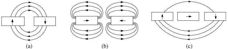
At present, the magnetized distributions of conventional PM arrays are radial and tangential, and their principles are shown in Figs. 2(a) and 2(b). In order to obtain a better performance of the airgap magnetic field, the radial and tangential arrays are combined to generate a new structure, namely Halbach array, which is shown in Fig. 2(c).
(a) (b) (c)
Figure 2. Structure diagram of different permanent magnet arrays. (a) Radial array. (b) Tangential array. (c) Halbach array.
The permanent magnets shown in Fig. 2(c) are arranged on the rotor surface, and their structures are shown in Fig. 3. Two types of Halbach array structures can be obtained by changing permanent magnet magnetization direction. The magnetic field distribution of the Halbach array with six permanent magnets per pole is shown in Fig. 4. The Halbach array shown in Fig. 4(a) enhances the external magnetic field of the rotor, which is used in the inner-rotor PM motor. The Halbach array shown in Fig. 4(b) enhances the inner magnetic field of the rotor, which is used in the outer-rotor PM motor. The Halbach array enhances the airgap magnetic field and reduces the magnetic flux density in the rotor yoke, so the thickness of the rotor iron can be reduced.
(a) (b)
Figure 3. Structure diagram of Halbach array rotors in the PM motors. (a) 2 permanent magnets per pole, (b) 4 permanent magnets per pole.
(a) (b)
Figure 4. Magnetic field distribution diagram of the Halbach array. (a) The external magnetic field of the rotor is enhanced. (b) The inner magnetic field of the rotor is enhanced.
x y
Magnetization direction PM
θm,i
θi θ = 0
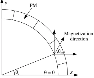
Figure 5. Schematic diagram of the permanent magnet magnetization direction.
in each pole. Fig. 5 is a simplified diagram of permanent magnet magnetization direction. Any segment magnetization direction can be calculated by the formula:
θm,i = (1±p)θi
θi = i−1
pN π (i= 1,2,3, . . . ,2pN)
where θm,i is the ith segment magnetization direction; p is the pole pair of the motor; + represents outer-rotor structures;−represents inner-rotor structures;θi is the angle betweenθ= 0 and the center of ith magnet segment; N is the number of segments per pole.
4. ANALYSIS OF ELECTROMAGNETIC CHARACTERISTICS
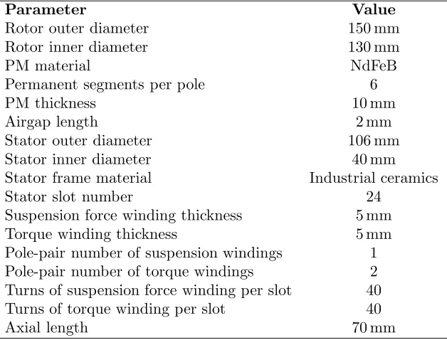
Figure 6(a) shows the structure of the outer-rotor and coreless-stator-type BPMSM with Halbach array. Table 1 presents the main structure parameters of the motor. It consists of an outer-rotor core with magnets mounted on the inner surface and a coreless stator with two sets of windings. The stator frame is made of non-magnetic materials, such as industrial ceramics. The four-pole torque windings areAm,
Bm andCm. The two-pole suspension windings areAs,Bs, andCs. The distribution of the two sets of windings is shown in Fig. 6(b).
1.3248e0 1.2420e0
1.1592e0 1.0764e0 9.9357e-1 9.1077e-1 8.2797e-1 7.4517e-1 6.6238e-1 5.7958e-1 4.9678e-1 4.1399e-1 3.3119e-1 2.4839e-1 1.6559e-1 8.2797e-2
0 B[tesla] Rotor
PM Airgap Suspension winding
Torque winding
Stator Shaft
As+
As
-Cs
-Cs+
Bs
-Bs+
Am+
Am+
Am
-Am
-Bm+
Bm+
Bm
-Bm
-Cm+
Cm+
Cm
-Cm
-(d)
(a) (b)
(c)
Figure 6. Analysis of the proposed motor model. (a) Structure of the proposed motor. (b) Stator winding distribution. (c) Magnetic field distribution. (d) Magnetic flux density distribution.
0 50 100 150 200 250 300 350
0 0.2 0.4 0.6
-0.2
-0.4
-0.6
circumference/mm
Airgap flux density/T
0 50 100 150 200 250 300 350
0 0.2 0.4 0.6
-0.2
-0.4
-0.6
circumference/mm
Airgap flux density/T
(a) (b)
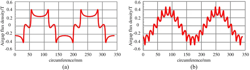
Figure 7. Airgap flux density distribution diagram of BPMSM with different magnet structures. (a) Conventional PM rotor, (b) Halbach array.
permanent magnets is the highest. However, the magnetic density of the rotor iron core is very low, far from reaching saturation level. Therefore, a large current can be used to excite the windings to improve the radial suspension force and electromagnetic torque.
Table 1. Specification of the prototype machine.
Parameter Value
Rotor outer diameter 150 mm Rotor inner diameter 130 mm
PM material NdFeB
Permanent segments per pole 6
PM thickness 10 mm
Airgap length 2 mm
Stator outer diameter 106 mm Stator inner diameter 40 mm Stator frame material Industrial ceramics
Stator slot number 24
Suspension force winding thickness 5 mm Torque winding thickness 5 mm Pole-pair number of suspension windings 1 Pole-pair number of torque windings 2 Turns of suspension force winding per slot 40 Turns of torque winding per slot 40
Axial length 70 mm
larger. In other words, it can improve the power density and torque density of the BPMSM, and reduce the volume and mass of the motor.
No-load EMF is an important parameter for the PM motor. As a motor, the no-load back-EMF will affect the dynamics and steady-state performance; as a generator, no-load back-back-EMF marks the output electric energy quality of generator. The speed of the motor is set to be 7500 r/min. Fig. 8 shows no-load back-EMF waveform for the torque windings. It can be seen that the back-EMF waveform is very sinusoidal, which is very favorable for the FESS.
The three-phase symmetrical alternating current is applied to the two sets of windings in the stator. The amplitude of the current of the torque winding Im is 10 A, and the amplitude of current of the suspension force windingIsis also 10 A. The pole pair of torque windings is 2. According to the formula:
f =np/60, the current frequency of the torque winding is set to be 250 Hz, wherenis the motor speed,
pthe torque winding pole pair, and f the current frequency. According to the condition that the stable suspension force is obtained [8], the current frequency of suspension force winding is also 250 Hz. When the suspension force winding is excited to generate force in the y-direction, the suspension forces in the x- and y-directions are shown in Fig. 9. In Fig. 9, a suspension force of 79 N is generated in the
y-direction, and a force nearly 0 is generated in thex-direction. Therefore, it can be concluded that the mutual interference of the suspension forces in thex- andy-directions is very weak, and the stale and controllable suspension force can be generated.
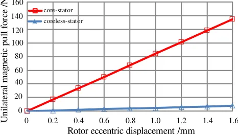
The unilateral magnetic pull force caused by the rotor eccentricity has a great influence on the rotor vibration and increases the difficulty of the rotor stability control. Therefore, it is necessary to study the unilateral magnetic pull force of the BPMSM. Fig. 10 describes the relationship between the unilateral magnetic pull force and the eccentric displacement of the rotor. It can be seen from the figure, the unilateral magnetic pull force of core-stator BPMSM with Halbach array is bigger than that of the coreless-stator BPMSM with Halbach array. With the increase of eccentric displacement of the rotor, the difference of unilateral magnetic pull force is greater. For the safety and stability of the motor operation, the unilateral magnetic pull force is expected to be small. Therefore, the coreless-stator BPMSM with Halbach array is more suitable for the FESS.
0 60 120 180 240 300 360 0 100 200 300 -100 -200 -300 Electricangle/deg Back-EMF/V
Figure 8. The back-EMF of torque windings when the motor runs at 7500 r/min.
10 20 30 40 50 60 70 80
2.5 5 7.5 10 12.5 15 17.5 20 22.5
0 20 40 60 80 100 120 140 160 180
0 10 20 30 40 50 60 70 80 90 -10
Rotor angular position /deg
S u sp en si o n fo rc e/ N Fx Fy
Figure 9. Radial suspension force when the suspension force winding is excited to generate force in the y-direction.
core-stator coreless-stator U n ila te ra l m ag n e tic p u ll fo rc e /N
0 0.2 0.4 0.6 0.8 1.0 1.2 1.4 1.6
Rotor eccentric displacement /mm
160 140 120 100 80 60 40 20 0
Figure 10. Relationships between unilateral magnetic pull forces and eccentric displacement of rotor.
2 3 4 5 6 7 8 9 10
Halbach array
Conventional PM rotor
0 2 4 6 8 10 12 14 16 18
Phase current amplitude of torque windings /A 0 1 2 3 4 5 6 7 8 To rq u e/ N .m
Figure 11. Relationships between torque and phase current amplitude of motor windings.
electromagnetic torque helps reduce the charge and discharge time of FESS. And Halbach array structure makes the motor torque ripple smaller. Therefore, the application of the BPMSM with Halbach array in the FESS is more advantageous.
5. ROTOR EDDY CURRENT LOSS ANALYSIS
When the conventional PM motor runs at low speed, the rotor eddy current loss is relatively small, and the impact on the performance of the motor is very weak. But when the PM motor runs at high speed, the frequency of the alternating magnetic field in the rotor core is very high, so the rotor eddy current loss is relatively large. In particular, the high-speed PM motor is used for the FESS in the vacuum environment, whose heat dissipation is more difficult than that of conventional PM motor. Therefore, in the FESS, the rotor eddy current loss is required to be as small as possible. In the BPMSM, the magnetic field generated by the suspension force winding and the rotor are in asynchronous operation. Therefore, the rotor eddy current loss of the BPMSM differs from that of the conventional PM motor, and the eddy current loss caused by the magnetic field of the suspension force winding is added. The analysis of rotor eddy current loss of high speed BPMSM is very necessary. Based on the already established transient FEA coupled with external circuit, the rotor eddy current loss of outer-rotor and coreless-stator-type BPMSM with Halbach array is analyzed in detail.
RA
RB
RC
Lend
Lend
Lend
WindingA
WindingB
WindingC
IA
IB
IC
Figure 12. The equivalent external circuit model of PM motor.
Loss(W/ )m2
2.4424e4 2.2898e4 2.1371e4 1.9845e4 1.8318e4 1.6792e4 1.5265e4 1.3739e4 1.2212e4 1.0686e4 9.1591e3 7.6326e3 6.1061e3 4.5795e3 3.0530e3 1.5265e3 6.9484e-10
Figure 13. Distribution diagram of rotor eddy current loss density when the motor is in idle run.
Figure 14. Rotor eddy current losses in three cases.
windings. The equivalent circuits of the two sets of windings in the stator are the same, both of which are shown in Fig. 12. The amplitude of the phase current of the winding is 10 A, and the frequency of the current is 250 Hz.
Figure 13 is the eddy current loss density distribution when the motor is in idle run. The amplitude of the current source in the external circuit is set to 0, and the motor runs at the synchronous speed. The rotor eddy current loss is very small because the coreless-stator and slotless-stator structure eliminates the stator cogging effect and reduces the rotor eddy current loss, which can meet the requirement of long-term and low no-load losses of the FESS.
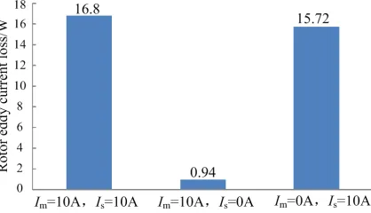
The rotor eddy current losses caused by the magnetic field of suspension force windings can be analyzed in theory. However, at present, there is no relative research on the influence of the magnetic field of the suspension force windings on the rotor eddy current losses by the simulations or experiments. Based on the FEA, the rotor eddy current losses of the BPMSM operating in three cases are analyzed. Fig. 14 is the simulation result of the rotor eddy current losses in three cases. When Im = 10 A,
Is = 10 A and Im = 0 A, Is = 10 A, the rotor eddy current losses are very close. When Im = 10 A,
Is = 0 A, the rotor eddy current loss is very small, which is about 5.6% of the rotor eddy current loss when Is = 10 A, Im = 10 A. The rotor eddy current loss generated by suspension force windings is far larger than that generated by torque windings.
Loss(W/ )m2
3.5619e6 3.3245e6 3.7994e6
3.0870e6 2.8496e6 2.6121e6 2.3746e6 2.1372e6 1.8997e6 1.6622e6 1.4248e6 1.1873e6 9.4985e5
4.7493e5 7.1239e5
2.3746e5 1.2944e-6
Loss(W/ )m2
2.6341e7 2.4694e7 2.3048e7 2.1402e7 1.9755e7 1.8109e7 1.6463e7 1.4817e7 1.3170e7 1.1524e7 9.8777e6 8.2315e6
2.0020e-4 6.5852e6 4.9389e6 3.2926e6 1.6463e6
Loss(W/ )m2
2.6528e6 2.4870e6 2.3212e6 2.1554e6 1.9896e6 1.8238e6 1.6580e6 1.4922e6 1.3264e6 1.1606e6 9.9482e5 8.2901e5 6.6321e5 4.9741e5 3.3161e5 1.6580e5 5.4565e-5
Loss(W/ )m2
1.1115e7 1.0420e7 9.7255e6 9.0308e6 8.3361e6 7.6415e6 6.9468e6 6.2521e6 5.5574e6 4.8627e6 4.1681e6 3.4734e6 2.7787e6 2.0840e6 1.3894e6 6.9468e5 2.7978e-5
(d)
(a) (b)
(c)
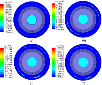
Figure 15. Rotor eddy current loss density distribution diagram of BPMSM with four structures. (a) Halbach array, coreless-stator. (b) Halbach array, core-stator. (c) Conventional rotor, coreless-stator. (d) Conventional rotor, core-stator.
Figure 16. Results of rotor eddy current losses of BPMSM with four structures.
6. CONCLUSIONS
In order to simplify the structure of FESS and improve the power density and efficiency of the system, an outer-rotor and coreless-stator-type BPMSM with Halbach array is proposed. On the basis of operation principle of outer-rotor BPMSM and analysis of the structure of Halbach array, the electromagnetic characteristics of the proposed motor are analyzed by FEA in detail. The rotor eddy current loss is analyzed by FEA coupled with external circuit combining with the external circuit. The conclusions are summarized as follows:
1) The BPMSM with Halbach array can generate stable and controllable radial suspension force, and obtain a larger electromagnetic torque compared with the conventional BPMSM.
BPMSM with the same rotor eccentric displacement is smaller. Therefore, the suspension force control system is easier to control the rotor stable suspension.
3) The eddy current loss of the magnetic field generated by the suspension force windings is accounted for the majority of the rotor eddy current loss of the BPMSM, and the magnetic field generated by the torque winding has little effect on the rotor eddy current loss.
4) The structure of the BPMSM has a great influence on the rotor eddy current loss. After comparing and analyzing the structures of four kinds of bearingless motors, it can be seen that the rotor eddy current loss of the coreless-stator BPMSM with Halbach array is the lowest.
5) The simulation results verify the theoretical analysis and the structure design, which are helpful to the further study of the application of motor in the FESS.
ACKNOWLEDGMENT
This work was supported by National Natural Science Foundation of China (61174055), Jiangsu Province “333 Project” (2014), Jiangsu Province “Qinglan Project” (2014).
REFERENCES
1. Dai, X. J., Z. F. Deng, G. Liu, et al., “Review on advanced flywheel energy storage system with large scale,” Transactions of China Electrotechnical Society, Vol. 26, No. 7, 133–140, 2011.
2. Lee, J., S. Jeong, Y. H. Han, et al., “Concept of cold energy storage for superconducting flywheel energy storage system,” IEEE Transactions on Applied Superconductivity, Vol. 21, No. 3, 2221– 2224, 2010.
3. Subkhan, M. and M. Komori, “New concept for flywheel energy storage system using SMB and PMB,” IEEE Transactions on Applied Superconductivity, Vol. 21, No. 3, 1485–1488, 2011.
4. Zhang, W. Y. and H. Q. Zhu, “Key technologies and development status of flywheel energy storage system,” Transactions of China Electrotechnical Society, Vol. 26, No. 7, 141–146, 2011.
5. Pan, Z. and R. A. Bkayrat, “Modular motor/converter system topology with redundancy for high-speed, high-power motor applications,” IEEE Transactions on Power Electronics, Vol. 25, No. 2, 408–416, 2010.
6. Ooshima, M., S. Kobayashi, and H. Tanaka, “Magnetic suspension performance of a bearingless motor/generator for flywheel energy storage systems,” Proceedings of IEEE Power Engineering Society General Meeting, 1–4, 2010.
7. Asama, J., M. Amada, N. Tanabe, et al., “Evaluation of a bearingless PM motor with wide magnetic gaps,”IEEE Transactions on Energy Conversion, Vol. 25, No. 4, 957–964, 2010.
8. Sun, X. D., L. Chen, and Z. B. Yang, “Overview of bearingless permanent magnet synchronous motor,” IEEE Transactions on Industrial Electronics, Vol. 60, No. 12, 5528–5538, 2013.
9. Nguyen, Q. D. and S. Ueno, “Modeling and control of salient-pole permanent magnet axial-gap self-bearing motor,”IEEE/ASME Transactions on Mechatronics, Vol. 16, No. 3, 518–526, 2011. 10. Xu, Y. L. and K. J. Feng, “Analysis on toothless permanent magnet machine with Halbach array,”
Proceedings of Power Electronics and Motion Control Conference, IPEMC 2006, 1–5, 2006. 11. Zhang, T., H. Q. Zhu, X. D. Sun, et al., “Optimization of permanent magnet type bearingless
motor using eddy current loss analysis,” Electric Machines and Control, Vol. 16, No. 10, 58–62, 2012.
12. Xia, C. L., L. Y. Guo, and H. M. Wang, “Modeling and analyzing of magnetic field of segmented Halbach array permanent magnet machine considering gap between segments,”IEEE Transactions on Magnetics, Vol. 50, No. 12, 2014.
13. Li, H. F. and C. L. Xia, “Halbach array magnet and its application to PM spherical motor,”
Proceedings of Electrical Machines and Systems, ICEMS 2008, 3064–3069, 2008.