Control Software Design and Safeguarding
with the support of UML and CT
P.M. Visser
M.Sc.Thesis
Supervisors
Prof.dr.ir. J. Van Amerongen
Dr.ir. J.F. Broenink
Ir. G.H. Hilderink
Ir. D. Jovanovic
September 2002
Report Number 19CE2002 Control Engineering
Abstract
This thesis will address the use of the Unified Modeling Language (UML) and Communicating Threads (CT) as a tool for designing control software. Since control systems are concurrent systems, the main focus is to explore the suitability of the concurrency model of UML. The CT-paradigm, developed by Gerald Hilderink, comprehends a special concurrency model for developing real-time software, which allows reasoning about concurrency issues and real-time behavior in an elegant way. Therefore it is interesting to research the integration of the CT-paradigm in UML. As a practical use-case, a safeguard is designed for a mechatronic setup.
UML is a third-generation object-oriented modeling language that rigorously defines the semantics of the object metamodel and provides a notation for capturing and communicating of object-structure and behavior. The UML provides tools to model various aspects of software design at a high level of abstraction. This coincides with the CT-paradigm that provides reasoning at a high level of abstraction about real-time and parallel software design. The UML tool Rhapsody is used for developing UML models, including the safeguard design.
CT is an object-oriented software package. This package provides a clear way of concurrent programming based on the theory of Communicating Sequential Processes (CSP). With CSP a concurrent system can be described by concurrently running processes that communicate with each other via channels. CTC++ is the implementation of the package in C++.
A comparison between UML and CT in terms of data transfer, synchronization and concurrent behavior is made. The comparison shows that in UML concurrency is defined on objects and on their operations. UML uses active –and passive objects to express concurrency and has no native semantical means to express priorities. Scheduling is thread based and the behavior of applications depends on underlying threading mechanism. CT provides channels to let processes communicate with each other. Channels encapsulate synchronization, concurrent behavior and data transfer. CT has extensive means to express concurrent behavior at a high level of abstraction. CTC++ uses ‘fair’ scheduling and its behavior is independent of a threading mechanism.
Samenvatting
Dit onderzoek richt zich op het gebruik van de Unified Modeling Language (UML) en Communicating Threads (CT) als een gereedschap voor het ontwerpen van regel software. Aangezien regelsystemen concurrent zijn ligt het aandachtspunt in het verkennen van het concurrency model van UML. Het CT-paradigma ontworpen door Gerald Hilderink bevat een speciaal concurrency model voor het ontwerpen van real-time software, welke het redeneren over concurrency zaken en real-time gedrag in een elegante wijze mogelijk maakt. Dit maakt het interessant om de integratie van het CT-paradigma in UML te onderzoeken. Als praktisch voorbeeld wordt een safeguard voor een mechatronische opstelling ontwerpen.
UML is een derde generatie object-georiënteerde taal die de semantiek van het object metamodel strict definieërd en voorziet in een notatie voor communicerend en object-gestructureerd gedrag. De UML voorziet in gereedschappen om verschillende aspecten van software ontwerp op een hoog niveau van abstractie te modelleren. Dit valt samen met het CT-paradigma, welke voorziet in het redeneren op hoog abstractie niveau van real-time en parallel software ontwerp. Het UML programma Rhapsody wordt gebruikt voor het ontwerpen van UML modelen, inclusief het ontwerp van de safeguard.
CT is een object-georiënteerd software pakket. Dit pakket voorziet in een duidelijke manier van concurrent programmeren op basis van de Communicating Sequential Processes (CSP) theorie. Met CSP kan een concurrent systeem worden beschreven door concurrent executerende processen die met elkaar communniceren via kanalen. CTC++ is de implementie van het pakket in C++.
Een vergelijk tussen UML en CT in termen van data overdracht, synchronizatie en concurrent gedrag wordt gemaakt. Dit vergelijk toont aan dat UML concurrency definieërd op objecten en hun operaties. UML maakt gebruik van actieve –en passieve objecten om concurrency uit te drukken en heeft van nature niet de semantiek om prioriteiten uit te drukken. Scheduling is gebasseerd op threads en het gedrag van applicaties is afhankelijk van het onderliggende threading mechanisme. CT verschaft kanalen om processen met elkaar te laten communiceren. Kanalen bevatten synchronizatie, concurrent gedrag en data overdracht. CT heeft uitgebreide middelen om concurrent gedrag op een hoog niveau van abstractie te beschrijven. CTC++ gebruikt een ‘eerlijke’ scheduling and het gedrag is onafhanklijk van een threading mechanisme.
CTC++ kan succesvol worden gebruikt als package in Rhapsody en de methode om de CTC++ package te maken wordt gegeven. Object model diagrammen worden geanalyseerd voor het gebruik van communicatie diagrammen en compositie diagrammen. De analyse toont aan dat object model diagrammen geschikt zijn voor het gebruik als communicatie diagram maar niet geschikt zijn voor het gebruik als compositie diagram. Een aanbeveling wordt gemaakt voor het ontwikkelen van een gereedschap, welke overeenkomt met UML maar uitgebreid is met additionele symbolen om concurrent gedrag uit te drukken. Toestands- en activiteitsdiagrammen en het implementatie mechanisme van Rhapsody om deze diagrammen te maken worden geanalyseerd. Een methode voor het gebruik van kanalen, parallele constructies, en keuze constructies in toestandsdiagrammen is gegeven of aangeraden. Een aanbeveling wordt gegeven voor het gebruik van een ander implementatie mechanisme voor een betere integratie van CTC++ in Toestands- en activiteitsdiagrammen.
Table of contents
1 Introduction ... 1
1.1 Unified Modeling Language ... 1
1.2 CSP and CT... 3
1.3 Outline of the report... 3
2 Concepts and Definitions ... 5
2.1 UML Concepts and Definitions ... 5
2.1.1 Objects and Classes ... 5
2.1.2 Message ... 5
2.1.3 Event ... 5
2.1.4 Concurrency... 6
2.2 CSP Concepts and Definitions... 6
2.2.1 Process ... 6
2.2.2 Event ... 6
2.2.3 Concurrency... 7
2.3 Comparison of concepts... 7
3 Data Transfer, Synchronization and Concurrent behavior ... 9
3.1 Data transfer... 9
3.1.1 Data transfer in CSP/CT ... 9
3.1.2 Data transfer in UML... 10
3.2 Synchronization ... 11
3.2.1 Synchronization in CT ... 11
3.2.2 Synchronization in UML and Rhapsody ... 11
3.3 Concurrent behavior... 12
3.3.1 Concurrent behavior in CT ... 12
3.3.2 Concurrent behavior in UML and Rhapsody... 14
3.4 Simple Processing Example... 15
3.4.1 Simple processing example in CTC++ ... 15
3.4.2 Simple processing example in Rhapsody ... 17
3.5 Outline... 18
4 How to use CTC++ within Rhapsody ... 19
4.1 Specifying objects as processes ... 19
4.2 CT and the object model diagram ... 20
4.2.1 Object model diagram as communication diagram ... 21
4.2.2 Object model diagram as composition diagram ... 24
4.3 Statechart diagrams, activity diagrams and CT... 26
4.3.1 From statechart diagram to implementation ... 26
4.3.2 Statechart diagrams vs. activity diagrams... 29
4.4 CTC++ applied in statechart diagrams... 30
4.4.1 Channels in statechart diagrams ... 30
4.4.2 Parallel constructs in statechart diagrams ... 31
4.4.3 Alternative constructs in statechart diagrams ... 33
viii
5 Safeguarding with UML and CT... 37
5.1 System description and safety requirements ... 37
5.1.1 Mechanics ... 37
5.1.2 Actuators/Sensors ... 37
5.1.3 Electronic Interface... 38
5.1.4 Controller... 38
5.1.5 Safeguard placement... 38
5.2 Safeguard specification and requirements ... 39
5.2.1 Specification of safeguard monitors ... 42
5.3 Safeguard design and implementation ... 44
5.3.1 Input shutter design... 45
5.3.2 Output shutter design ... 47
5.3.3 Current monitor design ... 48
5.3.4 Position monitor design ... 49
5.3.5 Cable condition monitor design... 50
5.3.6 EndStop monitor design ... 51
5.3.7 Speed monitor design ... 52
5.4 Outline... 53
6 Conclusions and Recommendations... 55
6.1 Conclusions... 55
6.2 Recommendations... 55
Appendices
A History of UML... 57B Appendices Chapter 4 ... 58
B.1 Making CTC++ available in Rhapsody ... 58
B.2 Importing CTC++ by Reverse Engineering ... 61
B.3 Changes made to CTC++... 62
B.4 Changes to Rhapsody Framework component OMThread ... 62
B.5 Setup to use Linux as deployment system for Rhapsody... 64
B.6 Ambiguity with condition connector ... 69
B.7 Statechart elements of Rhapsody. ... 70
B.8 Rhapsody Specifics... 73
B.9 Counter Example ... 75
B.10 Implementation of CTC++ package with postprocessing ... 77
C Appendices Chapter 5 ... 82
C.1 Naming conventions for safeguard design... 82
C.2 Coupling 20-sim to Rhapsody as test enviromnent... 83
Introduction 1
1 Introduction
Control systems operate in a world that is parallel by nature. Control systems typically consist of multiple sensors and actuators that operate simultaneously. At each sampling the sensor data must be analyzed and responses must be calculated. Control systems have well defined, fixed-time constraints that must be met. In addition to this, user-interface tasks, safety tasks, supervisory tasks and possibly tasks for additional control loops should be performed concurrently. When the computational resources are limited, these tasks should possibly be performed with different priorities, e.g. to make sure that the deadlines will be met. To create efficient and reliable software, the software should reflect this natural concurrency (Welch, Peter H., 1998). Concurrent software can result in a higher throughput, higher responsiveness or reactiveness, increase in fault tolerance and, perhaps the most important factor, reduced complexity of the design.
The independent data streams from the sensors and other inputs should be manipulated such that the proper response can by generated within the defined deadlines or otherwise the system will fail. This tends to complicate the software. In addition, implementing concurrency on a single-processor system introduces difficulties. The system is only able to execute a single instruction at a time. Accordingly, it is not possible to run multiple processes (tasks) at the same time. Only a virtual form of parallelism is possible by switching between parallel processes. This way of implementing parallelism requires the use of a scheduling mechanism. This implies problems of when and how scheduling takes place. One can program concurrency by using the traditional approach of directly controlling the threads that are related to the various tasks. This approach is however hard and error-prone (Drunen, 2000). Threads are low-level entities that are difficult to control and to understand. Directly controlling threads involves a good understanding of the flow of control of concurrent processes. This extensively increases the complexity and development time for those kinds of programs. In addition, there are problems inherent to concurrency. Examples are starvation, livelock, deadlock, race conditions, non-determinism and shared resources management (Welch, P. and Justo, 1993).
1.1 Unified Modeling Language
The Unified Modeling Language (UML) is a language for expressing the constructs and relationships of complex systems (Douglass, 1998). It is a third-generation modeling language that rigorously defines the semantics of the object-metamodel and provides a notation for capturing and communicating object structure and behavior. The UML represents a collection of best engineering practices that have proven successful in the modeling of large and complex systems. The UML is very expressive and effectively supports a variety of software development processes and business applications.
UML defines eight diagram types that document the system software from different viewpoints and at different points in the software process (Booch et al., 1999). Some diagrams are very abstract showing a high-level view of the system without much detail. Others show a lot of detail about of a small part of the system. UML diagrams show a higher-level view of the system that is hard to grasp when looking at just the code. The eight diagrams that are used are:
• Use Case Diagram, displays relationships between use cases and actors. Describes context of the
system. May be used to formalize and develop behavioral requirements.
• Class Diagram, shows classes, packages and their associations, displays relationships such as
containment, inheritance, associations and others. Describes the static data used by the system. Shows the separation of the system into packages. Also shows objects and their relationships at a particular time during the execution of a system. Useful for documenting complex data structures and object topology.
• Interaction diagrams:
• Sequence Diagram, shows order of events exchanged by objects during the execution of a
scenario. Shows how objects collaborate to implement the behavior of the system. This consists of the vertical dimension (time) and horizontal dimension (different objects).
• Collaboration Diagram, shows the same information as the Sequence Diagram in a different
format. Lines labeled with events connect object nodes. Displays an interaction organized around the objects and their links to one another.
• Statechart Diagram, shows the lifecycle of an object as a state machine. Displays the
sequences of states that an object of an interaction goes through during its life in response to received stimuli, together with its responses and actions
• Activity Diagram, displays a special state diagram where most of the states are action states
and most of the transitions are triggered by completion of the actions in the source states. This diagram focuses on flows driven by internal processing.
• Physical diagrams:
• Component Diagram, displays the high level packaged structure of the code itself.
Dependencies among components are shown, including source code components, binary code components, and executable components. Some components exist at compile time, at link time, at run times well as at more than one time.
• Deployment Diagram, shows topology of the hardware components and software components
executing the system. Software component instances represent run-time manifestations of code units.
The UML is a graphical notation only. You must choose a software development process that defines which diagrams to create and the order in which to create them. Using a software development process enables many UML analysis constructs to be automatically mapped to an implementation language such as C, C++, or Java. Automatically mapping models to an implementation language can increase developer productivity, improve the quality of the system software, and enable a team to react more quickly to changes in requirements. Automatic mapping has the added advantage that the models and code are always in sync because the code is generated from the models. The effort to create models in the analysis phase will continue throughout the entire lifecycle. Two main software development processes are Rational Rose and I-Logix Rhapsody. Based on the results of the course Real-Time Software Development the software development process I-Logix Rhapsody will be used in this thesis.
Introduction 3
1.2 CSP and CT
In 1985 Hoare introduced the concept of CSP (Communicating Sequential Processes), a notation and theory for describing and analyzing concurrent systems (Hoare, 1985). The CSP theory was more recently brought up to date by Roscoe (Roscoe, 1997) and Schneider (Schneider, 2000). It provides a mathematical notation for describing patterns of communication using algebraic expressions and contains formal proofs for analyzing, verifying and eliminating undesirable conditions, such as race hazards, deadlocks, livelock, and starvation. With CSP the behavior of concurrent software can be described in terms of processes, events and composition operators. Channels are used to let processes communicate with each other. When processes communicate they engage in a communication event. The rules that are derived in CSP can be applied to verify the behavior of the software to guarantee a satisfied behavior. The CSP concept is well thought-out and has been proven to be successful for realizing concurrent software for real-time embedded systems (Grebe, 1993).
CT, Communicating Threads, is an object oriented software package currently being developed by
Gerald Hilderink (Hilderink, G.H. et al., 2000). CT is an implementation of a subset of CSP principles. CTC++ is the C++ implementation, which will be used in this thesis project.
1.3 Outline of the report
Concepts and Definitions 5
2 Concepts and Definitions
This chapter describes the key concepts and definitions of UML and CSP that are applicable in the context of this thesis assignment. After defining the concept a short comparison is made between UML and CSP and some of the main differences are mentioned.
2.1 UML Concepts and Definitions
This section summarizes UML concepts and definitions as found in the OMG UML specification version 1.4 (OMG-UML, 2001).
2.1.1 Objects and Classes
Classes and objects are two fundamental concepts in UML. A class is an abstraction of a set of real-world entities that have the same data and behavior. A class may have many instances called objects. Each object conforms to the rules defined by its class. Attributes define the data encapsulated in the class. When modeling a class, only include the attributes, services, and states required by the application. Classes cooperate with one another to satisfy the requirements of the system. Associations link classes together. Classes communicate with one another by passing events and invoking services.
In UML two types of objects are distinguished:
• An active objectis one that owns a thread of control and may initiate control activity and runs
concurrently with other active objects.
• A passive object is one that holds data, but does not initiate control. However, a passive object
may send Stimuli in the process of processing a request that it has received. It shares common thread with other passive objects.
2.1.2 Message
A message is a specification of a communication. It defines the roles of the sender and the receiver instances, as well as which association role specifies the communication link. The message is connected to an action, which specifies the statement that, when executed, causes the communication specified by the message to take place. If the action is a call action or a send action, the signal to be sent or the operation to be invoked in the communication is stated by the action. The action also contains the argument expressions that, when executed, will determine the actual arguments being transmitted in the communication. Moreover, any conditions or iterations of the communication are also specified by the action. Apart from send action and call action, the action connected to a message can also be of other kinds, like create action and destroy action. In these cases, the communication will not raise a signal or invoke an operation, but cause a new instance to be created or an already existing instance to be destroyed. In the case of a create action, the receiver specified by the message is the role to be played by the instance, which is created when the action is performed.
2.1.3 Event
An event is a type of message. It is a specification of a type of observable occurrence. The occurrence that generates an event instance is assumed to take place at an instant in time with no duration. Strictly speaking, the term “event” is used to refer to the type and not to an instance of the type. However, on occasion, where the meaning is clear from the context, the term is also used to refer to an event instance.
Event instance
full flexibility for modeling different types of communication facilities. An event is receivedwhen it is placed on the event queue of its target. An event is dispatchedwhen it is dequeued from the event queue and delivered to the state machine for processing. At this point, it is referred to as the current event. Finally, it is consumed when event processing is completed. A consumed event is no longer available for processing. No assumptions are made about the time intervals between event reception, event dispatching, and consumption. This leaves open the possibility of different semantic models such as zero-time semantics.
2.1.4 Concurrency
The occurrence of two or more activities during the same time interval. Concurrency can be achieved by interleaving or simultaneously executing two or more threads.
Concurrency in respect to operations of passive and active objects.
The concurrency of operations specifies the semantics of concurrent calls to the same passive object.
Active objects control access to their own operations so this property is usually (although not required in UML) set to sequential. The concurrency can be specified as:
• Sequential: Callers must coordinate so that only one call to an instance (on any sequential
operation) may be outstanding at once. If simultaneous calls occur, then the semantics and integrity of the system cannot be guaranteed.
• Guarded: Multiple calls from concurrent threads may occur simultaneously to one instance (on
any guarded operation), but only one is allowed to commence. The others are blocked until the performance of the first operation is complete. It is the responsibility of the system designer to ensure that deadlocks do not occur due to simultaneous blocks. Guarded Operations must perform correctly (or block themselves) in the case of a simultaneous sequential operation or guarded semantics cannot be claimed.
• Concurrent: Multiple calls from concurrent threads may occur simultaneously to one instance (on
any concurrent operation). All of them may proceed concurrently with correct semantics.
Concurrent operations must perform correctly in the case of a simultaneous sequential or guarded Operation or concurrent semantics cannot be claimed.
2.2 CSP Concepts and Definitions
This section summarizes CSP concepts and definitions (Roscoe, 1997). The main reason that the concepts and definitions defer from the UML concepts is that CSP was designed for describing and analyzing systems whose primary interest are the ways in which different components interact at the level of communication at a higher level of abstraction.
2.2.1 Process
A CSP process is completely described by the way it can communicate with its external environment. The external environment of a process is usually another process.
2.2.2 Event
The event, or communicating event, is the most fundamental object in CSP. Events are assumed to be drawn from a set, which contains all possible communications for processes in the universe under consideration. Communication describes a transaction or synchronization between two or more processes rather than the transmission of data one way. An event can only happen when all its participants are prepared to execute it. The fundamental assumptions about event communications in CSP are:
• Events are instantaneous.
Concepts and Definitions 7
2.2.3 Concurrency
Concurrency is an abstraction of behavior where the system is viewed as a set of parallel, sequential, and alternative processes that communicate with each other. It ignores the speed of execution due to the absence of any absolute notion of real time.
The notions of real time, priorities, and scheduling are refinements that underlie the abstraction of concurrency.
2.3 Comparison of concepts
In UML there are multiple types of communication, events are one of those types. Events can be both asynchronous and synchronous. In CSP there is one type of communication, the communication event. This event is synchronous.
The UML makes no assumption between the transmission links of object; it allows freedom to fit an applicable communication mechanism. This can lead to loss of events, reordering or duplication. In CSP events there will not be loss of events, reordering or duplication between processes.
In UML concurrency is defined on objects and on their operations. In CSP concurrency refers to the way processes behave. Processes are abstracted from real-live entities and will reflect their natural behavior.
Data Transfer, Synchronization and Concurrent behavior 9
3 Data Transfer, Synchronization and Concurrent behavior
This chapter will elaborate on the differences between data transfer, synchronization and scheduling in UML and CSP, more specifically the difference in scheduling between Rhapsody and CTC++. In order to shed some light in the scheduling schemes both Rhapsody and CTC++ will be analyzed. This chapter first describes the differences between UML and CT and is concluded by a demonstrating example. The goal of this chapter is to demonstrate the necessity to use CSP/CT for real-time control software design in UML/Rhapsody.CSP provides channels to let processes communicate with each other. Channels provide communication between processes and encapsulate synchronization, concurrent behavior and data transfer. The UML uses events to communicate between objects. Events do not capture synchronization, concurrent behavior and data transfer in the same fashion as a CSP channel does. The differences between data transfer, synchronization and scheduling will be elaborated. Examples created in Rhapsody and CTC++ will be used to show specific cases.
3.1 Data transfer
3.1.1 Data transfer in CSP/CT
Figure 1 depicts two communicating processes. Process A can send or receive data to or from
Process B by use of a channel.
Process A channel Process B
send/receive
Figure 1 : Communicating Processes
In CT channels perform data transfer on communication. The type of channel specifies the type of data that is transferred. For instance, a channel of integer will transfer integers from one process to another. Figure 2 depicts two communicating processes. Process A will write value x and Process B
will read value x.
Process A w rite x channel read x Process B
Figure 2 : CT and data transfer
Figure 2 shows that Process A sends data to Process B. Since it is important to know the direction
of communication CTC++ provides two special types of channel interfaces to specify the direction of data transfer. These channel interfaces are ChannelInput and ChannelOutput. The ChannelInput
only allows a read on the channel (read method). The ChannelOutput only allows a write on the
channel (write method).
The CTC++ implementation of the example in Figure 2 looks like this:
Process A interface: Process_A(ChannelOutput_of_Integer *channelout);
Process A body: channelout→write(&x);
Process B interface: Process_B(ChannelInput_of_Integer *channelin);
3.1.2 Data transfer in UML
In the UML objects need to be associated with other objects in order to enable messaging. Messaging is an abstraction of data and/ or control information passed between objects and doesn’t refer to the actual data transfer. In order to send messages between objects an association must exist between the objects. The object model diagram in Figure 3 shows two objects that are connected with an association.
object_A 1 communication 1 object_B
Figure 3 : OMD of two associated objects in UML
An association is a relationship that permits the exchange of messages among objects. (Douglass, 1999) UML associations are by default bi-directional and support messaging in either direction. Associations can be chosen to be uni-directional and in that case an open arrowhead points to the receiving object.
The implementation of an association is a pointer. Thus the association relations in Figure 3 results in: • A property of object_A that contains a pointer to object_B.
• A property of object_B that contains a pointer to object_A.
Thus in other words, objects will have to know each other in order to communicate. This is a fundamental difference when compared to CT. In CT processes don’t know each other, a process has an interface consisting out of channels to enable communication to its environment. The way channels connect processes determines the data transfer. The processes don’t determine the communication flow themselves as object in UML do.
Now to the actual data transfer between object_A and object_B. Different messaging
implementations are possible, for instance: direct method calls or events. The latter is discussed since it is also a mechanism for synchronization and scheduling. In order to transfer data from object_A to object_B a message event needs to be sent from object_A to object_B. The UML event instance is
an object itself and will contain the data that is to be transferred. The type of data can be specified by parameterization of the event. A parameter in the context of an UML event is an unbound variable that can be changed, passed, or returned. The sequence diagram in Figure 4 depicts the message event that is send.
Figure 4 : Sequence diagram UML data transfer
The sequence diagram shows that object A sends an event evData with parameter x to object B.
Although in this example object A is the sender of the event and object B is the recipient of the
event this does not determine the direction of the data transfer. The direction of data transfer depends on the specification of parameter x. If parameter x is defined as type in data can be transferred from object A to object B. If parameter x is defined as type out date can be transferred from object B to object A. If parameter x is defined as in/out data can be transferred in both directions. Rhapsody
Data Transfer, Synchronization and Concurrent behavior 11
Summarizing, objects need an association in order to allow exchange events. The direction of data transfer depends on the specification of the parameters of the event. Processes don’t need to be associated with other processes. The interface of a process consists of channel inputs or outputs, which determines how a process communicates with its environment.
3.2 Synchronization
3.2.1 Synchronization in CT
In CT, channels encapsulate synchronization. Communication only takes place when both sender and receiver are ready. In the example of Figure 2, process A only sends data to process B when both
processes are ready. This is called rendezvous communication. Channels are basically unbuffered, however, buffers may be added to compensate for communication latencies. (Jovanovic et al., 2002)
3.2.2 Synchronization in UML and Rhapsody
In UML both synchronous as asynchronous communication is possible. Synchronous communication in UML is referred to as invoking an operation. Asynchronous communication in UML is referred to as sending a signal (OMG-UML, 2001). The UML does not specify an implementation mechanism for asynchronous or synchronous communication. The actual implementation mechanism is left to the UML tool, which can vary among different tools.
The UML tool used in this thesis project is Rhapsody. The rest of this section will describe the mechanism Rhapsody uses. In Rhapsody, the mechanism used for synchronous communication is called a triggered operation. The mechanism for asynchronous communication is called an event. In communication between objects there is a sender and a recipient. The sender will create the triggered operation or event. The recipient will consume the event. A recipient can consume an event if a statechart diagram or an activity diagram describes its behavior. In other words, an object can consume an event if it is reactive. Reactive behavior is described by a statechart –or activity diagram. If a sending object sends an event to a receiving object, it will continue immediately and not wait for the recipient. The event is placed in the event queue of the receiving object. Events in the queue are handled in the sequence they are received.
If a sending object sends a triggered operation to a receiving object, it will wait until the receiving object has executed the triggered operation. If there are other events pending in the recipient’s queue these will be handled first.
In context of the recipient there is no difference between triggered operations and events. Both are received and consumed in the order they arrive.
Rhapsody discourages the use of both triggered operations and events at the same time. The behavior can be unpredicted and can lead to possible unwarranted results.(UserGuide, 2002)
3.3 Concurrent behavior
3.3.1 Concurrent behavior in CT
In CT channels perform scheduling. All the scheduling is performed on the read -and write actions of channels. The actual scheduling is determined by the manner in which the processes are composed. CT basically offers the following compositional constructers:
• Sequential construct, this construct combines processes into a construction in which one process follows another. The processes are performed sequentially.
• Parallel construct, combines a number of processes, which are performed in parallel. • Alternative construct, combines a number of processes guarded by inputs. The alternation
performs the process associated with a guard that is ready.
• Priority Parallel construct, the same as a Parallel construct but with priority. • Priority Alternative construct, the same as a Alternative construct but with priority.
The manner in which these compositional constructs operate will be demonstrated with an example.
Sequential composition
The scheduling of the sequential composition will be demonstrated with the following example. There are two processes, process A and process B. Process A will receive a value from its environment.
Process B will send a value to its environment. Both processes will run sequentially. The semantics
of this figure are based on the work of Gerald Hilderink (Hilderink, Gerald H., 2002). Figure 5 depicts the sequential example.
Process A
output input
Process B
Figure 5 : Sequential Composition
The implementation of this sequential composition has the following form in CTC++.
Sequential seq1 = new Sequential(); seq1→add(process_A);
seq1→add(process_B);
This composition can be run by calling the run method of the sequential process. The behavior is
straightforward, process A will read from its channel and then sequentially process B will write to
its channel. If both processes are looped this sequence will repeat itself.
Parallel composition
The scheduling of the parallel composition will be demonstrated with the following example. There are two processes, Process A and Process B. Process A will receive a value from its environment.
Process B will send a value to its environment. Both processes will run in parallel. The situation is
depicted in Figure 6.
Process A
output input
Data Transfer, Synchronization and Concurrent behavior 13
The implementation of this parallel composition has the following form in CTC++.
Parallel par1 = new Parallel(); par1→add(process_A);
par1→add(process_B);
This composition can be run by calling the run method of the parallel constructor. The behavior in this case is in parallel. Either process A will read from the channel and then process B will write to
the channel or vice versa. This interleaving is non-deterministic. Remember that the processes can only read or write if the process they are connected to is ready to write or read. Now consider the case that both processes will continuously perform read –and write operations. By means of this parallel construction both processes will perform one read and write action before the next read or write action.
Alternative composition
The scheduling of the alternative composition will be demonstrated with the same example as is used by the parallel construct. The difference is now that both processes will read or write the moment they can actually read or write. Process A will be able to read its value if the channel from which it reads
is ready. Process B will be able to write its value if the channel from which it writes is ready. If both
channels are ready at the same time, only one of the channels is read or written. Figure 7 depicts the alternative composition of two processes.
Process A
guard2 guard1
Process B
Figure 7 : Alternative Composition
The implementation of this Alternative composition has the following form in CTC++.
Guard *guard_A = new Guard(channelinput_A); Guard *guard_B = new Guard(channelouput_B); Guard *guardlist = {guard_A, guard_B};
Alternative *alt1 = new Alternative(guardlist, 2);
This composition can be run by calling the run method of the alternative constructor. The alternative alt1 can be used as a switch statement. The alternative will return value 0 if process A can read
from its channel. It will return a value 1 if process B can write to its channel. When a guard is ready
the associated process will read or write its channel. Thus the scheduling behavior in this case is that both processes will read respectively write the instant their channel becomes ready.
Priority Parallel composition
The piority parallel composition adds priority to the parallel composition. Priority is expressed by an arrow on the compositional symbol. Figure 8 depicts the priority parallel composition of two processes.
Process A
output input
Process B
Process A will have a higher priority than Process B. Lower priority processes may only continue when all higher priority processes are unable to.
Priority Alternative composition
The priority alternative composition adds priority to the alternative composition. Figure 9 depicts the priority alternative composition of two processes.
Process A
guard2 guard1
Process B
Figure 9 : Priority Alternative Composition
Process A will have a higher priority than Process B. If the guards of both processes become ready at the same time the process with the highest priority will be selected and run.
3.3.2 Concurrent behavior in UML and Rhapsody
The UML doesn’t specify actual scheduling. The scheduling mechanism is determined by the UML tool used. If necessary the UML allows the designer to specify one’s own specific scheduling mechanism. UML distinguishes two types of objects in terms of concurrency. (For details about the exact definition see chapter 2.)
• Active objects; an object that owns a thread of control and may initiate control activity.
• Passive objects; a passive object is one that holds data, but does not initiate control.
The two types can be used in Rhapsody. Active objects can be used by specifying active as the type
of concurrency for the object. Passive objects can be used by specifying sequential as the type of concurrency of the object. Note that Rhapsody uses a different name for passive objects. The definition the objects are also slightly different when compared to the exact UML definitions.
• Active objects are application objects with active concurrency. An active object runs on the thread of its own task.
• Sequential objects have sequential concurrency, which means that the system runs on a single thread and all operations are executed in sequential order.
Rhapsody provides support for one’s own specific scheduling mechanism by offering various concurrency -and synchronization objects. Types that are provided are message queue objects, mutex objects, resource objects, semaphore objects and timer objects. Some of these types are predefined in the Rhapsody framework, the remaining types have to be defined by the designer.
The actual scheduling is thus thread based and depends on the thread library used. The Rhapsody object execution framework (OXF) represents threads by the class OMOSThread. This class wraps an
operating system thread and adds the behavior, which is necessary for the framework. (For more details see (OXF-Guide, 2002)) This means that the scheduling of Rhapsody depends on the operating system it runs. Thus the same model can behave differently on different platforms.
Data Transfer, Synchronization and Concurrent behavior 15
3.4 Simple Processing Example
The goal of this section is to show the differences between Rhapsody and CTC++ applied to an actual example. This section shows the difference in design of the example and the working of the example. The example models a system that has two inputs and two outputs. The choice for multiple inputs and multiple outputs has been made to collaborate with a controller system which usually has multiple inputs and outputs. The input signals are independent and need to be read and computed. The signals can be read and written instantaneous, there is no blocking. Both signals should be treated as equally important. The computation on the signals is the same. Figure 10 displays the data flow diagram of this example.
Reader A Computer A
Reader B Computer B input: signal A
input: signal B
output: signal A
output: signal B
Figure 10 : Data flow diagram of simple processing example
The aim for this system is to be reactive; both signals need to be read and computed in time with equal priority.
3.4.1 Simple processing example in CTC++
The readers and computers are implemented as processes. Reader A and Computer A communicate
with a channel. Reader B and Computer B communicate with a channel. Both pairs run in parallel.
Figure 11 depicts the composition of the processes in this example.
Reader A Computer A
Reader B Computer B
Figure 11 : Composition diagram of processing example
Figure 11 graphically demonstrates the processing example. Currently, there is no tool that can translate such a diagram in code. This is one of the reasons for the use of UML, which allows graphical modeling. The actual composition has to be made manually. The composition can be made as described in the previous sections. The composition is as follows:
Par Seq
Reader A Computer A Seq
Reader B Computer B
The readers are simple processes that send a value to the computers through a channel. The input signal is omitted since it can be read instantaneous; hence there is no input channel for the reader. The behavior of the reader is specified in the run method.
void Reader::run{ while (TRUE) {
channeloutput_signal->write(&position); }
}
The computers are simple processes that read from their input channel and print a message. The behavior of the computer is specified in the run method.
void Computer::run{ while (TRUE) {
channelinput_signal->write(&position); printf(“Computed X\n”);
} }
Now that the behavior of the processes is defined and the composition has been made, the composition is run. The output of this example in CTC++ is as follows:
Computed A Computed B Computed A Computed B Computed B Computed A Computed A Computed B Computed A Computed B Computed B Computed A
The output is straightforward and shows that every cycle both signals are read and computed. The output shows that the system treats both signals with equal priority and hence the system is reactive on both inputs. The actual sequence of which signal is read and computed is non-deterministic. The CT++ example will give the same output independent on which operating system it runs. CTC++ treats both signals equally since it implements ‘fair’ scheduling.
Furthermore, the example can be easily extended in CTC++. Assume that the reading of the signals take some time, either because there is a hardware latency or some signal preprocessing that has to be performed. Assume that the computation also needs some time. Instead of executing the read and computation sequentially they can be executed in parallel for a better reactivity. The reactivity will be better because the computation can be performed while the reader has to wait for the hardware. If the reader has read a signal before the computer is finished it will wait for the computer. If the computer has finished computing it will wait for the reader. This extension is easy in CTC++. The processes do not need to be changed, the only change is in the composition. Figure 12 reflects the changes.
Reader A Computer A
Reader B Computer B
Data Transfer, Synchronization and Concurrent behavior 17
3.4.2 Simple processing example in Rhapsody
The readers and writers are implemented as active objects. In UML relations between objects are depicted in object model diagrams. Figure 13 shows the object model diagram of the processing example.
reader_A:Reader
1
computer_A:Computer
1
reader_B:Reader
1
computer_B:Computer
1
1
1
Figure 13 : OMD of processing example
Rhapsody supports automatic code generation. The OMD in Figure 13 will be translated into the appropriate classes, objects and their relations. The behavior of the reader and the computer will be graphically modeled in an activity diagram and statechart diagram. An activity diagram is used to specify the behavior of the reader because it consist out of a single read action. Figure 14 shows the activity diagram of the reader.
getItsComputer()->trigopPosition(position);
Figure 14 : Activity diagram of Reader
The activity diagram translates to an endless loop of triggered operations. The position will be passed as a parameter.
A statechart diagram is used to specify the behavior of the computer because it ‘waits’ on the signal and will compute the signal on reception. The statechart diagram of the computer is depicted in Figure 15.
Compute
trigopPosition/printf("Computed %c\n",Identifier);
Figure 15 : Statechart diagram of Computer
The statechart diagram shows that on every reception of the triggered operation trigopPosition()
some output is printed to the screen.
The behavior of the reader and computer is simple in this example and can be easily written by hand. However, in more complex examples, statechart diagrams and activity diagrams will facilitate the design and testing of complex behaviors. Furthermore these diagrams are WYSIWIG and can be understood by looking at them.
The output of this example on different operating systems. Windows 98 Linux
Computer A Computer A
Computer B Computer B
Computer A Computer A
Computer A Computer A
Computer A Computer A
Computer A Computer A
Computer B Computer A
Computer B Computer A
Computer B Computer A
Computer A Computer A
Computer A Computer A
Computer B Computer B
Computer B Computer B
Computer B Computer B
Computer B Computer B
Computer B Computer B
Computer A Computer B
The output shows that there is a difference in behavior between both the operating systems. The behavior is different because UML uses threads for its concurrent behavior. Since the operating systems use different threading mechanisms the output differs. As previously mentioned, this is not wanted behavior for controller systems. The same model may not behave fundamentally different just because it runs on another (operating) system.
Furthermore, the responsiveness of the Rhapsody model will be lower than the CTC++ model. A deadlines could be missed because sometimes one signal is read and computed five times before the other signal is read and computed. The overall performance can be higher, since the amount of context switches is limited, but its importance subordinate to the reactivity.
3.5 Outline
The basics about data transfer, synchronization and concurrent behavior of both CSP/CT and UML/Rhapsody have been discussed and compared. This chapter showed that CSP has extensive means to express concurrent behavior at a high level of abstraction. UML is thread based and has ‘only’ active –and passive objects to express concurrency and no native semantical means to express priorities.
Furthermore, this chapter showed that a system designed and implemented in CTC++ uses ‘fair’ scheduling and its behavior is independent of the operating system on which it runs. A system designed and implemented in Rhapsody is thread based and its actual behavior depends on the threading mechanism used, which is operating system depended.
How to use CTC++ within Rhapsody 19
4 How to use CTC++ within Rhapsody
This chapter describes how to use the CTC++ package within Rhapsody. In more general terms speaking; using the CTC++ package in Rhapsody is using the CSP concepts in conjunction with UML. Wherever possible generalizations will be made and restrictions of Rhapsody or the CTC++ package will be indicated. This chapter starts by specifying a process-oriented view in UML, followed by an approach on how to make communication diagrams and composition diagrams in UML. Then an analysis is made on how to use statechart –and activity diagrams with CTC++. Appendix B.1 contains the approach to make CTC++ available in Rhapsody, this is a prerequisite before using CTC++ within Rhapsody.
4.1 Specifying objects as processes
The CT paradigm reasons about processes, communication between processes, and concurrency between processes. This section describes how to specify processes using objects.
When using CTC++ without Rhapsody, thus writing C++ code by hand, a process can be made by specifying the process interface to the class by inheritance. The process interface enforces the subclass to implement the run method. The example class Writer demonstrates this specific inheritance.
class Writer : public Process { ………
}
When using Rhapsody, the same inheritance needs to be made. There are three slightly different methods to achieve this inheritance:
• Stereotyping. • Inheritance relation. • Superclass selection.
All these methods will yield the same result but differ in the easiness to use, a suggestion towards a specific method will be made.
Stereotyping
A class can be stereotyped as a Process by adding the Process type to the stereotype field in the
feature dialog of the class. The result can be viewed in the object model diagram; the stereotype of a class is visible between brackets. Figure 16 depicts this for an example class called Writer.
Writer <<Process>>
Figure 16 : Object model diagram of class Writer
The base class property of the stereotype <<Process>> needs to be set to public Process in order to
generate the correct code. The advantage of stereotyping is the clear visibility in the object model diagram. It is elegant and WYSIWYG. The disadvantage is that stereotypes cannot be stored in a package for reuse in other models.
Inheritance relation
Process
Writer
Figure 17 : Object model diagram of inheritance relation
The advantage of this method is its good readability. The disadvantage is that for every process class to be used this relation has to be drawn resulting in either an object model diagram with many classes or many object model diagrams.
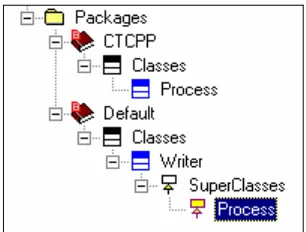
Superclass selection
A superclass can be selected by selecting the “add new superclass” method in the browser tree. A drop down box appears and the class Process can be selected. Figure 18 shows the result of this
approach.
Figure 18 : Superclass in browser tree
The advantage of this method is its easiness to use. The disadvantage is that the superclass is not visible in an object model diagram, such that there is no graphical distinction between an object and process.
The recommended approach for to specify processes is the superclass selection. The approach is easy and reusable.
4.2 CT and the object model diagram
The object model diagram (OMD) displays and sets relationships among objects and classes. Classes an objects are not distinguished in the OMD other than in the respect that an object is an instance of a class. An OMD shows that objects can communicate with each other, classes that inherit from each other, classes that own each other and so on. The common types of relationships that exist between classes in an object model diagram are association, aggregation, composition, generalization, and dependency.
In CT, process are related to each other in the following two ways:
1. Processes communicate with each other. These can be displayed in a communication diagram. 2. Processes relate to each other in terms of execution order; which processes are executed in
How to use CTC++ within Rhapsody 21
• It means that there is a direct mapping between the diagram and the code, between the specification and the implementation.
4.2.1 Object model diagram as communication diagram
The best way to explore if an object diagram is suited as a communication diagram is by constructing a test case. The test case consists of two processes and one channel:
• Process Producer, this process will produce integer values to a channel of integer.
• Process Consumer, this process will consume integer values from a channel of integer.
• Channel_of_integer, this channel is the medium between the Producer and the Consumer. Figure 19 shows the communication diagram for this example.
Producer Integer Consumer Channel
Figure 19 : Communication diagram of Producer Consumer example The communication diagram is mapped to the object model diagram depicted in Figure 20.
producer:Producer
1
channel:Channel_of_Integer
1
consumer:Consumer
1
channelin 1
channelout 1
Figure 20 : Object model diagram of Producer-Consumer example
The main difference between the communication diagram and the object model diagram is that the channel is explicitly visible in the latter. This is necessary for automatic code generation due to the following two reasons:
• A channel can be used only if it is instantiated; a channel is an object. The object model diagram of Rhapsody allows it classes to be specified as objects in the instance dialog.
• The relation between the producer, consumer and the channel needs to be specified in order to be set automatically.
In order to translate the object model to a working implementation the producer and consumer need to be instantiated also. The object model diagram shows the names of the instances and the names of the classes separated by a colon.
The associations in the object model diagram of Figure 20 are uni-directional towards the channel. This has to be the case since a process uses a channel. The channel does not use a process and hence does not use a relation towards that process. Setting an association from a process to a channel results that within the process the channel is known and can be used for a read or write action on the channel. In this specific case the class Producer will have a protected property of type Channel_of_Integer*
named channelout. Section 3.1.1 showed that CTC++ normally uses the interface class ChannelOutput that only allows write actions. It is not possible to use this interface class in a object model diagram because the result of the automatic code generation cannot provide the right syntax for use of the class. Thus naming heuristics have to be used in the object model diagram. In this case, the name channelout is chosen to reflect that the channel should be used as an output channel only.
The object model diagram is translated into code by Rhapsody in the following manner. When instances and relations are specified, Rhapsody generates a function called initRelations(). This
function is build of two separate functions: OMCreateInstances() and OMConnectRelations()
The function OMCreateInstances() contains the code to create the instances. For this example the
code is:
static void OMCreateInstances() { channel = new Channel_of_Integer; consumer = new Consumer;
par = new Parallel; producer = new Producer; }
The function OMConnectRelations() contains the code to set the relations. For this example the code
is:
static void OMConnectRelations() { producer->setChannelout(channel); consumer->setChannelin(channel); producer->setItsParallel(par); }
When writing CTC++ code by hand, the relations between processes and channels are specified in the interface of the process. In the generated code the relations between processes and channels are specified in the properties of the process. However, this will yield the same behavior.
This section showed that object model diagrams of UML are suited to depict communication diagrams. Furthermore, Rhapsody provides direct code mapping which means that drawing the communication diagram in an object model diagram maps directly to the implementation. A useful feature in the object model diagram is multiplicity as will be explained in the next section.
Multiplicity and the communication diagram
In an object model diagram, multiplicity refers to the number of instances of one class that may relate to a single instance of an associated class. Thus multiplicity is an easy mechanism to create many instances from a single class. Figure 21 shows the producer-consumer example in case there are ten producers and ten consumers.
producer:Producer
10
channel:Channel_of_Integer
10
consumer:Consumer
10
channelin 1
channelout 1
Figure 21 : OMD Producer-Consumer with multiplicity
The diagram shows that the processes and the channel have a multiplicity of ten while the multiplicity of the associations remains one. This might seem strange but consider that each producer has a single relation with each channel and it will make sense.
Rhapsody uses a special container class OMlist to keep a list of pointers of the class that will have
multiplicity. The definition can be found in the header file of the package.
extern OMList<Producer*> producer;
How to use CTC++ within Rhapsody 23
The variable i is used for the iteration. Knowing the way the instances are created is useful. For
instance for uniquely naming each producer and consumer in the example of Figure 21. The class Producer can be extended with an attribute called Identity. This attribute will contain a unique identity for each instance of the class Producer. In order to set this Identity a constructor containing this attribute is added to the class Producer. This actual call of an instantiation can be specified in the instance dialog box of the class Producer provided by Rhapsody. The constructor containing the identity argument can be selected and as actual parameter the value i is given. This will result in the
creation of ten producers each having a unique identity ranging from 1 to 10. The actual instantiation will look like this:
for (int i = 0; i < 10; i++) producer.add(new Producer(i));
The setting of the relations will be done in the function OMConnectRelations(). The implementation
of Rhapsody shows another special class in order to properly setup the relations. This special class is named OMIterator and is used to iterate through the OMList of pointers of the object. In order to set the relations between two objects with multiplicity, two definitions of OMIterator are necessary. The
next piece of code shows how the ten instances of the class Consumer are connected to the ten instances of the class of Channel_of_Integer.
OMIterator<Consumer*> frIter(consumer);frIter.reset();
OMIterator<Channel_of_Integer*> toIter(channel);toIter.reset(); while (*frIter){
(*frIter)->setChannelin(*toIter); toIter++;
if(!(*toIter)) {
toIter.reset(); }
frIter++; }
The loop that sets the relations is straightforward, except the if(!(*toIter)) expression. This
expression will test if the OMList on the arrow side of the relation has not yet reached it end. If it has reached its end, the Iterator starts again from the beginning of the list. This means that there is no check that the multiplicity on both ends of a relation is the same. This is not a bug but the Rhapsody tool will not check if the multiplicity between two objects matches. In this case; if there would be ten consumers but only 5 channels the relations will be connected like this:
Consumer 1,6 à Channel 1 Consumer 2,7 à Channel 2 Consumer 3,8 à Channel 3 Consumer 4,9 à Channel 4 Consumer 5,10 à Channel 5
4.2.2 Object model diagram as composition diagram
The composition diagram shows how the processes relate to each other in terms of execution order. Figure 5, Figure 6 and Figure 7 in chapter 3 depict respectively the sequential, parallel and alternative compositions. This section explores the possibility to use the object model diagram as a composition diagram.
In order to use the object model diagram as a composition diagram it needs to express the various constructs. The construct witch will be analyzed first is the parallel construct.
In the object model diagram five common types of object relationships exist. On a first glance the composition relation sounds appealing. Unfortunately composition in this respect refers to a strong form of aggregation. The UML concept of aggregation applies to objects that physically or conceptual contain other objects. This concept is not useful for the composition, which needs to be made. The association relationship type is the only type that has the potential to be used in a composition diagram. An association between two objects means that two objects are connected and that messaging between the two objects is possible.
The object model diagram in Figure 22 shows a parallel construct with two associations to its supposed member processes.
parallel
process1 process2
add
1 1
add
Figure 22 : Possible OMD Composition of Parallel construct
The association is directed from the parallel construct to the processes because processes themselves have no notion about the construct they run under. Graphically this OMD displays a parallel construct with a use relation to its member processes. However, this OMD cannot be mapped to the correct implementation. The class of the parallel construct is given (The Parallel construct is found in the CTC++ library) and may not be subject to changes. Furthermore, it is illogical to adapt the construct because a process needs to be added. This means that the parallel composition cannot be successfully made in the object model diagram.
A sequential composition cannot be made either. With a sequential composition it is obligatory to add the processes in a certain order. This order cannot be displayed in an object model diagram.
Unfortunately the object model diagram seems not be suited to draw a composition diagram. This means that the composition has to be made manually. The actual composition of processes entails adding these processes to a CT construct. Afterward the composition needs to be run. The processes and the CT constructs have to be instantiated first before the composition can be made. The code to instantiate the processes will be auto generated if the communication diagram is drawn in an object model diagram. If the CT constructs are added to this object diagram, or drawn in a separate object diagram, these will be automatically instantiated as well. Figure 23 shows the situation for two processes that communicate through a single channel and should be run in parallel.
How to use CTC++ within Rhapsody 25
consumer:Consumer
1
producer:Producer
1
par:Parallel
1
channel:Channel_of _Integer
1
channelin channelout
1
1
Figure 23 : OMD Composition example
To make an actual composition, a function named composition() will be added to the functions of
the package. Every composition is a process and therefore has a run() function. The run() function will be added to the functions of the package. Figure 24 shows the browser view of these functions.
Figure 24 : Browser view of composition() and run() function
The functions are called when the generated application of the package is started if added to the initialization functions. The functions can be added in the feature dialog of the current package under the property AdditionalInitialization.
The body of composition() function for this example is: void Composition() {
par->add(producer); par->add(consumer); }
The body of run() function for this example is: void run() {
par->run(); }
Multiplicity and composition
Figure 21 shows multiplicity of the producer-consumer example in case there are ten producers and ten consumers. This means that the composition will consist out of adding the ten producers and consumers to the parallel construct. This composition will be made manually in the composition()
function. The instances of the producers and consumers are auto generated, the task that remains is adding the multiple instances to parallel construct. The multiplicity can be made by applying the
OMIterator class by hand as follows:
OMIterator<Consumer*> ConsIter(consumer1);ConsIter.reset(); OMIterator<Producer*> ProdIter(producer1);ProdIter.reset(); while (*ConsIter && *ProdIter){
}
4.3 Statechart diagrams, activity diagrams and CT
This section first describes statechart diagrams and activity diagrams in detail. It is pointing out possibilities and restrictions. In the second part CT concepts will be used in collaboration with statechart diagrams and activity diagrams.
4.3.1 From statechart diagram to implementation
This section addresses the scheme that Rhapsody implements to translate statecharts into C++ code. The UML leaves room for design tools to have their own symbols for the elements; Appendix B.7 describes all the elements that can be used in Rhapsody statecharts. The most important elements will be discussed to understand the statechart thoroughly, in order to use the CT concepts.
The implementation of a Rhapsody statechart is basically just a plain function consisting out of sequential code. Within the context of a statechart the type and origin of an event are not relevant, an event merely spans the transition between two states. Thus, the notion of an asynchronous or synchronous event is not relevant within the context of a statechart. The “statechart function” is called by the event dispatcher to take corresponding action upon occurring events. (OXF-Guide, 2002) The elements and their semantics that are discussed, are: states, events, transitions, guards and actions. After these elements have been described, orthogonal states will be discussed.
The implementation scheme is explained based on a few examples of simple statecharts containing the elements to be explained. Figure 25 shows a simple statechart with two states.
state_0 state_1
ev
Figure 25 : Simple statechart example This statechart contains out of the following elements:
• Two empty states: state_0 and state_1. Empty means that the states contain no actions or
substates.
• Three transitions of a different type:
1. A Default transition; the transition to state_0.
2. A Null transition; the transition form state_0 to state_1.
3. A Triggered transition; the transition triggered with event ev from state_1 to state_0
When the startBehavior method of the instance of the class containing this statechart is called the
statechart will be activated (initialized). The default transition will be taken and state_0 is entered. The Null transition, a transition without a trigger, will be taken and state_1 is entered. The transition
from state_1 to state_0 is taken on event ev. Then the Null transition will be taken again and so on. The implementation of this statechart will look like this:
(Some code is omitted in order to explain the main behavior and not be bothered with small details.)
int ActivateStatechart () {
How to use CTC++ within Rhapsody 27
int res = eventNotConsumed; switch (state) {
case state_0 {
if (NULL_EVENT) { popNullConfig(); state=state_1; res = eventConsumed; }
break; }
case state_1 { if (ev) {
pushNullConfig(); state=state_0
res = eventConsumed; }
break; }
default: break; }
return res; }
The functions pushNullconfig and popNullconfig will respectively increment and decrement the
counter for ‘Null events’. When this counter has a value higher than zero then there are ‘Null events’. In this case the event dispatcher will create a ‘Null event’ if necessary. A ‘Null event’ will be created when residing in a state without other events and the only way to leave the state is a ‘Null transition’. If the state connected to a default transition has a ‘Null transition’ the function ActivatieStatechart will do a pushNullConfig. Furthermore, states with an outgoing ‘Null transition’ will do a popNullConfig and states with an incoming ‘Null transition’ will do a pushNullconfig.
The function ActivateStatechart is the implementation of the default transition. This function
creates a Null event and sets the statechart to its initial state, in this case to state_0.
The function statechart represents the implementation of the remainder of the statechart. The code
shows that the function is a switch-statement, the switch being the current state. Inside each case statement an if-statement will evaluate the transition that needs to be taken. Since both states have only one outgoing transition both case statements only consist out of one statement. The if-statement of state_0 will evaluate if a ‘Null Event’ has occurred. The if-statement of state_1 will
evaluate if event ev1 has occurred. The action upon a true evaluation is setting the state to the state
the outgoing transitions points to.state_1.
state_0 state_1
ev2 ev1[Guard]/Action
Figure 26 shows the previous statechart appended with a trigger, guard and an action on the transition from state_0 to state_1.
state_0 state_1
ev2 ev1[Guard]/Action
The addition of the trigger will make the ‘Null transition’ a triggered transition and there will be no more ‘Null transition’ in the statechart. This will result in the removal of the functions
pushNullConfig and popNullConfig.
By applying a trigger, a guard and an action to the transition from state_0 to state_1 the
case-statement of state_0 will look like this: case (state_0)
{
if (ev1) if (Guard) {
Action;
state=state_1; res = eventConsumed; }
break; }
The Guard can be seen in the implementation as another statement inside the body of the event if-statement. If the guard will evaluate true the action the action is executed and the state is set to
state_1. However, if the guard will evaluate