Volume 2010, Article ID 939542,9pages doi:10.1155/2010/939542
Research Article
Harmonic Enhancement in Low Bitrate Audio Coding Using
an Efficient Long-Term Predictor
Jeongook Song, Chang-Heon Lee, Hyen-O Oh, and Hong-Goo Kang
Department of Electrical and Electronic Engineering, Yonsei University, 134 Sinchon-dong, Seodaemun-gu, Seoul 120-749, Republic of Korea
Correspondence should be addressed to Jeongook Song,[email protected]
Received 8 February 2010; Revised 11 May 2010; Accepted 29 July 2010
Academic Editor: Tan Lee
Copyright © 2010 Jeongook Song et al. This is an open access article distributed under the Creative Commons Attribution License, which permits unrestricted use, distribution, and reproduction in any medium, provided the original work is properly cited.
This paper proposes audio coding using an efficient long-term prediction method to enhance the perceptual quality of audio codecs to speech input signals at low bit-rates. The MPEG-4 AAC-LTP exploited a similar concept, but its improvement was not significant because of small prediction gain due to long prediction lags and aliased components caused by the transformation with a time-domain aliasing cancelation (TDAC) technique. The proposed algorithm increases the prediction gain by employing a deharmonizing predictor and a long-term compensation filter. The look-back memory elements are first constructed by applying the de-harmonizing predictor to the input signal, then the prediction residual is encoded and decoded by transform audio coding. Finally, the long-term compensation filter is applied to the updated look-back memory of the decoded prediction residual to obtain synthesized signals. Experimental results show that the proposed algorithm has much lower spectral distortion and higher perceptual quality than conventional approaches especially for harmonic signals, such as voiced speech.
1. Introduction
The main objective of speech and audio coding algorithms is to represent an input signal with as few bits as possible while maintaining high perceptual quality; however their funda-mental design concepts are somewhat different. The reason can be found in the unique characteristics of input signal to be encoded, and the application areas of each codec. For example, speech coding that employs the voice production mechanism is used for bidirectional communications, while audio coding that utilizes the hearing mechanism is used for one-way broadcasting services in general. Due to the different design concept one method does not work well for other type of input signals [1].
As the communication and broadcasting networks are merging together, demands for developing a unified speech/audio codec are rapidly increasing [2]. As a first step toward this unification, MPEG standardized the MPEG-4 audio which combines a large set of codecs covering different signal characteristics and operating bit rates [3]. The 3GPP also standardized the adaptive multirate wideband plus (AMR-WB+) codec that has the combined structure
with an ACELP technology and a transform-based coding (TCX) scheme [4]. Recently, MPEG has initiated a new standard to provide a unified coding tool for speech and audio signals. In response to the Call for Proposal (CfP) on the unified speech and audio coding (USAC), 8 candidate systems have been submitted, and a reference model was selected through a competitive evaluation process [5,6]. The reference model has a combined architecture containing two separate coding branches: one comes from a modification of advanced audio coding (AAC), and the other comes from a traditional linear prediction-based coding especially the AMR-WB+ [6,7].
To design a unified speech and audio codec, it is important to fully understand the signal characteristics of input signal as well as the type of distortions related to the codec used, that is, the effect caused by encoding speech signals with audio codec and vice versa. It is well known that transform-based codecs are inadequate to efficiently express the speech input signals, especially at low bitrates [8,
said to be one of the most significant reasons [10, 11]. In other words, relatively long transform analysis leads to roughness, because the pitch is rather frequently varied in the transform duration, and thus the harmonic components in the frequency domain are not ensured to be preserved by perceptual bit allocation. As an another aspect, it should be also noted that each peak and valley coming from the pitch harmonics might be independently coded in the transform domain, thus it is less efficient to code them as much as to be done by namely long-term prediction in many speech coders [12].
The AAC-LTP introduced a concept to the transform coder as an intention to remove the harmonic redundancy where the prediction was designed to reduce the interframe redundancy [13]. However, the quality improvement was marginal because of its inherent structural limitation in the encoding step, that is, a modified discrete cosine transform (MDCT) with a time-domain aliasing cancelation (TDAC) [14, 15]. Since the MDCT in AAC has a long frame size and needs additional one-frame delay to reconstruct the aliasing-free time domain signal, the lag of the predictor should be very long. Therefore, the prediction gain becomes low because it applies to less correlated signal. Obviously, the method could not be applicable to speech input signals having pitch harmonics, and rather it may be appropriate to code very tone-like stationary musical solo signals such as pitch-pipe and violin.
This paper proposes a new long-term prediction struc-ture that can be integrated into transform-based audio cod-ing algorithms. The harmonic components of input signal are first reduced by a deharmonizing long-term predictor, and then the predicted signal is encoded and decoded by a transform coder. Finally the effect of the deharmonization predictor is compensated by a long-term synthesis filter that minimizes the overall quantization error between the input and the synthesized signal. Since the look-back memory of the compensation filter has been updated by the decoded signal of the previous frame, it provides higher prediction gain, which results in much lower perceptual distortion. The performance of the proposed algorithm is verified by implementing it with the Enhanced aacPlus (EAAC) codec released by 3GPP [16]. Simulation results obtained from objective and subjective tests confirm the superiority of the proposed algorithm especially for speech and concatenated signals.
2. Limitation oF AAC-LTP
The AAC-LTP has been designed to enhance harmonic components of the input signal using a long-term predictor [13].
Figure 1 shows the encoding blocks of AAC-LTP. In addition to the typical T/F (time to frequency) transform module with the psychoacoustic model, it includes a long-term prediction (LTP) module. The residual signal remain-ing after the LTP process is adaptively quantized in the “Quantizer and Coding” block using the psychoacoustic model, and the encoded bitstream is packetized depending
on “Bitstream Encoder/Multiplexer” block. “Long-term syn-thesis” and “F/T” blocks in the LTP module generate the synthesized signal that is also used for updating the loop-back memory of long-term prediction. The output of the long-term prediction, s(n), is represented by a lag to the previously synthesized signal, and a first-order prediction coefficient, such as
s(n)= ⎧ ⎨ ⎩
bs(n−N−d), n=0,. . .,d−1,
bs(n−N−d), n=d,. . .,N−1, (1) whereNis the length of frame,bis a prediction coefficient,
dis a prediction lag,s(n) is the previously synthesized signal, ands(n) is the aliased signal between s(n) and s(n−2N) as shown inFigure 2. Please note that the predicted samples should be always taken from a delay of at leastN samples, and this filter has to employ the aliased part. Since the audio codec uses the MDCT, it is not possible to obtain a perfectly reconstructed signal without introducing one frame delay to keep the time domain aliasing cancelation (TDAC) characteristic [17]. The one frame delay has to be included because it needs one frame data of a synthesized signal when it is compared with original signal in the “Frequency Selective Control” routines, which requires to compare the encoding performance of the predicted signal to that of the original signal in the transform domain. For example, in case a current frame is predicted from the previous N
samples starting at s(n0 −N), we are not able to get the
samples betweens(0) ands(n0−1) since they have not been
reconstructed yet.
Consequently, the pitch searching range of AAC-LTP should be set betweens(n−2N) ands(n−N) as depicted inFigure 2.Table 1depicts examples of LTP performance to speech input samples, which shows percentages of operated frame rates and prediction gains. This simple experiment was executed in original signal domain without quantization in order to fairly examine the effect of prediction delay to the prediction gain. The gains of the prediction, which works on previous frame signals, are compared to those with no delay. The operated frame rates show the ratio of frames that LTP processing is applied. Though the speech samples Speech 1∼Speech 4 include large portion of voiced regions, the operated frame rate of selecting the AAC-LTP module is under 10%. Please also note that the gains of the prediction, obtained by the previous frame signals, are much lower than those with no delay. In other words, the AAC-LTP does not work properly for speech samples in general. Subjective listening tests also showed that the AAC-LTP did not have a good performance for speech samples [13].
3. Proposed Algorithm
Psychoacoustic model Side information Bitstream
encoder/ multiplexer Quantizer
and coding Frequency
selective control T/F
Input signal S(n)
Inverse frequency selective switch and inverse quantization T/F Long-termprediction F/T
LTP module
s(n)
S(n)
s(n)
S(ω)
SL(ω) SL(ω)
S(ω)
Figure1: Block diagram of the encoding process of AAC-LTP [13].
Table1: The prediction gain of AAC-LTP.
Speech 1 Speech 2 Speech 3 Speech 4 Speech 5 Speech 6
Operated frame rate (%) 4.0 8.2 1.9 2.9 22.1 28.9
prediction gain (dB) no delay 16.78 14.94 15.00 10.27 12.48 14.12
1 frame delay 3.23 4.16 3.62 2.60 2.46 5.97
Pitch searching range
s(n−2N)
Aliased part
s(n−N) N+d
s(n)
Figure2: Pitch searching range of AAC-LTP.
buffers in each processing stage. At first, a residual ri(n),
where i indicates a frame index, is obtained through the deharmonization predictor. We have
B(z)=1− m
p=−m
bh,pz−dh+p, (2)
where bh,p is prediction coefficients,dh is a pitch lag, and mdepends on the filter order. By passing the input signal,
si(n), through this transfer function, the residual component, ri(n), is obtained. To improve the efficiency of the prediction,
the analysis frame is divided into 4 subframes. By setting the search range of pitch delay to cover the full range of human being’s fundamental frequencies, that is, 93.75∼960 Hz [18,
19], the optimal pitch lag that maximizes autocorrelation is determined. After applying transformation to the residual signal, the transformed coefficients are further encoded by T/F encoder, and the quantized residual in the previous frame, ri−1(n), is obtained as shown in Figure 4(b). To
make the decoder suitable for performing an analysis-by-synthesis structure, it essentially needs an inverse transform module that converts the transformed coefficients back into
time domain. Since one frame delay exists due to “T/F” and “F/T” processing [17], the next process depicted in
Figure 4(c)uses the delayed residuals,ri−1(n). The final step
of the proposed algorithm is reminimizing the quantized error of T/F encoder using the closed-loop-based long-term synthesis, which generates the most similar output among the decoded candidates. The synthesized candidatesc,i−1(n)
is obtained as follows:
sc,i−1(n)=ri−1(n) + m
p=−m bc,psi−1
n−dc+p , (3)
wherebc,pdenotes candidates for optimal prediction coeffi
-cients,dcdenotes a candidate for an optimal pitch lag, andm
determines the filter order. The closed-loop predictor does not invoke any additional delay for inner calculation. To obtain an optimal pitch value, a criterion of mean square error between the synthesized signalsc,i−1(n) and the input
signalsi−1(n) is defined as follows:
do,bo,−m,. . .,bo,m
= argmin
{dc,bc,−m,...,bc,m}
N−1
n=0
si−1(n)−sc,i−1(n) 2
,
(4)
where bo,p denotes optimal prediction coefficients, and dodenotes an optimal pitch lag. The variablesbc,panddcare
given in (3). The optimal pitch related parameters computed in the closed-loop synthesis process should be transmitted to the decoding stage. The buffer of compensation filter is filled with the final output,si−1(n), for the next frame:
si−1(n)=ri−1(n) + m
p=−m bo,psi−1
Table2: Additional bit allocation.
Parameter 1st sub-frame 2nd sub-frame 3 rd sub-frame 4th sub-frame Total per frame
LTP-filtering 1 1 1 1 4
Pitch info. 9 6 6 6 27
Calibration 2 6 6 6 20
Total 51
si−1(n)
ri(n) si(n)
(a)
si−1(n) ri−1(n)
(c) Harmonic compensation
filter
Quantization and coding
F/T
T/F Aliased
Ri,i−1(k)
Psycho-acoustic model (b) T/F encoder
De-harmo -nization predictor
MSE Delay
Figure3: Encoder block diagram of the proposed algorithm.
Table3: Simulation environment.
Specification
Test Database materials from MPEG USAC
Sampling frequency 48 kHz
Bitrates 12, 16, 20 kbps
Cut-offfrequency 3.328 kHz
Window shape only long window
Output Input ri(n)
si(n) si−1(n)
−N
−2N 0 N
(a) Deharmonization predictor
Output Input
ri−1(n)
ri(n) ri−1(n)
ri−2(n)
−N
−2N 0 N
(b) T/F Encoder
Output Input
si−1(n)
ri−1(n)
si−2(n)
−N
−2N 0 N
(c) Harmonic compensation filter
Figure4: Encoder buffer of the proposed algorithm in each stage.
3.2. The Decoder of the Proposed Algorithm. The structure of decoder consists of the T/F decoder and the long-term syn-thesis block as shown inFigure 5.Figure 6describes the two blocks of memory buffer of the proposed algorithm in each decoding stage. The T/F decoder works for the quantized
T/F decoder Long-termsynthesis Aliased
Ri,i−1(k)
(a) (b)
ri−1(n) si−1(n)
Figure5: Decoder block diagram of the proposed algorithm.
Output Input Input
ri−1(n)
Aliased Ri−1,i−2(k)
Ri.i−1(k)
Aliased
−N
−2N 0 N
(a) T/F decoder
Output Input
si−1(n)
ri−1(n)
si−2(n) −N
−2N 0 N
(b) long-term synthesis
Figure6: Decoder buffer of the proposed algorithm in each stage.
residual,ri−1(n), with previous and current aliased signals as
shown inFigure 6(a). Then the synthesized signal,si−1(n), is
obtained through the long-term synthesis process given in (5), that is, by utilizing optimal prediction coefficients and optimal pitch lag.
Table4: Average spectral distance of speech signal.
Average spectral distance (dB) Speech 1 Speech 2 Speech 3 Speech 4 Speech 5 Speech 6
Proposed algorithm 6.13 6.45 6.77 6.17 5.81 5.27
EAAC without LTP 6.57 8.04 7.40 7.25 7.27 5.79
2500 3000 3500
−2000
−3000
−1000 0 1000 2000 3000
Sample
4000 4500 Original
Residual
Residual differentiation
Figure7: The result of long-term prediction with fixed subframe length.
is set to N samples in the long window case. If the frame is divided into four subblocks with fixed length, an interval of each subblock becomes N/4 samples, which is helpful for increasing prediction gains. In this blockwise prediction method, however, it is inevitable to see artifacts at the block boundary if the prediction gain rapidly varies in consecutive blocks. Let the residual and original signal in the previous and current subframe be ri−1, si−1,ri,si, respectively. The
transform domain signals in the overlap region are expressed as follows,
Sol(w)= N−1
n=N/2
si−1(n)e−jwn+ N/2−1
n=0
si(n)e−jwn,
Rol(w)= N−1
n=N/2
ri−1(n)e−jwn+ N/2−1
n=0
ri(n)e−jwn,
(6)
whereNis an overlap frame length,iis a frame index,Sol(w)
is an original signal of transform domain, and Rol(w) is a
residual signal of transform domain. If the prediction lags between previous and current subframe are same, and the filter order is one, previous residual and current residual are expressed as
ri−1(n)=si−1(n)−bo,i−1s(n−di), ri(n)=si(n)−bo,is(n−di).
(7)
2500 3000 3500
−2000
−3000
−1000 0 1000 2000 3000
Sample
4000 4500
Original Residual
Residual differentiation
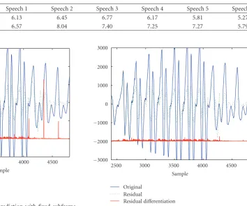
Figure8: The result of long-term prediction with flexible subframe length.
From (6) and (7), we get the residual signal represented by
Rol(w)=Sol(w)−bo,i−1Sol(w)e−jwdi
+bo,i−1−bo,i N/2
n=0
si(n−di)e−jwn.
(8)
The last term in (8), (bo,i−1−bo,i) N/2
n=0si(n−di)e−jwn, causes
the artifacts over all frequencies. If the original signal is band-limited, the residual signal is also band-limited. However, as the difference of the prediction gain between consecutive frames becomes larger, artifacts become more severe.
Figure 7 depicts an example of artifacts obtained by second-order differentiation. The thin solid line is the original signal, the dashed line is a residual signal with long-term prediction, and the thick solid line denotes the absolute value of the second-order difference obtained by the residual signal as follows:
x(n)= |{r(n)−r(n−1)} − {r(n−1)−r(n−2)}| = |r(n)−2r(n−1) +r(n−2)|, (9)
0.3 0.4
0 0.1 0.2 0.5
0 1000 2000 Fre q u en cy (H z) 3000 Time (s) (a) 0.3 0.4
0 0.1 0.2 0.5
0 1000 2000 Fre q u en cy (H z) 3000 Time (s) (b) 0.3 0.4
0 0.1 0.2 0.5
0 1000 2000 Fre q u en cy (H z) 3000 Time (s) (c)
Figure9: An example of speech spectrogram: (a) original signal, (b) synthesized signal using proposed algorithm, and (c) synthesized signal using EAAC without long-term prediction.
to use the technique in our case because another type of distortion such as time delay and windowing effect could occur. In this paper, a novel flexible frame length algorithm is proposed to solve the problem. The proposed algorithm is composed of two processing steps. In the first step, the boundary position of subframe is determined to minimize the net signal power at the boundary. The position of the net signal power,p, is obtained by following:
p= ⎧ ⎪ ⎪ ⎪ ⎪ ⎪ ⎪ ⎨ ⎪ ⎪ ⎪ ⎪ ⎪ ⎪ ⎩ argmin
0≤n<N/16 n=M/2
n=−M/2 s N 4
j−1 +n, j=1 ,
argmin
−N/8≤n<N/8 n=M/2
n=−M/2 s N 4
j−1 +n, j=2, 3, 4 ,
(10)
where jis a subframe index,Nis a subframe length, andM
is the number of adjacent samples. When the constant,M,
1 0 2 0 −2 −1 1 2
×104
(sec) (a) original signal
1 2 4 Spect ral distanc e (dB) 0 0 2 6 8 10 12 14 16 18 20 (sec) Proposed algorithm EAAC without LTP
(b) spectral distance
Figure10: Spectral distance of speech signal.
is too large, net signal power does not provide the optimal position claimed by the lowest power due to the summation of lower region and larger region. Consequently, less adjacent samples could be determined as the subboundary set in the transition period.
The value, p, is adapted for changing the boundary position between subframes. Through this calibration, the discontinuity can be removed perfectly as given inFigure 8.
4. Implementation
The proposed algorithm is integrated into the EAAC released by 3GPP because of its high encoding efficiency and good sound quality compared to the other AAC versions, but it does not have a long-term prediction module. The dehar-monization predictor and the compensation filter consist of the first-order filter, which is more stable and requires small amount of additional bits.
Music
Speech Concatenated Mixed
20 40 60 80 100 120
Hidden reference EAAC
Proposed algorithm Hidden anchor 12 kbps
(a)
Music
Speech Concatenated Mixed
20 40 60 80 100 120
Hidden reference EAAC
Proposed algorithm Hidden anchor 16 kbps
(b)
Music
Speech Concatenated Mixed
20 40 60 80 100 120
Hidden reference EAAC
Proposed algorithm Hidden anchor 20 kbps
(c)
Figure11: Results of MUSHRA test at (a) 12, (b) 16, and (c) 20 kbps.
step. Our simulation results show that as the difference becomes higher we may easily notice artifacts. To overcome the problem, we fixed the prediction coefficients for the deharmonization step. Although the method could not enjoy the full advantages of using LTP, it does not have the artifact problem and has reasonably good performance. Besides, It does not need to allocate additional bits for the coefficient of the deharmonization filter. If the prediction gain of the encoded frame is not high, only the mode bit is transmitted. Pitch interval is encoded by a differential quantization scheme, but the first subframe uses full pitch range to improve perceptual quality and to be robust to channel errors. To reduce discontinuous artifacts at frame boundaries, the boundary of each subframe is adaptively controlled depending on signal characteristics. For the input signal of 48 kHz sampling frequency, the proposed algorithm only requires the side information of 1kbps, and it might be further reduced when some entropy coding schemes are introduced.
4.2. Perceptual Entropy in T/F Encoder. The T/F encoder needs to compute perceptual entropy (PE) that is defined as the number of bits required for encoding the short term spectrum of the signal [20,21]. The perceptual entropy of residual signal is adopted as follows:
PE= 1
2π
π
0 max
0, log2R
ejw T(ejw)
dw
bit sample
, (11)
whereR(ejw) is a power spectral density of residual signals
andT(ejw) denotes the masking threshold density of original
signals which is computed in each scale factor band. The modified PE and the masking threshold are utilized for the quantization and encoding process [16].
5. Performance Evaluation
environments are summarized in Table 3. To make a fair comparison, additional side information needed for the proposed harmonic compensation method is taken into account in the bit allocation of the T/F encoder.
In the encoding block diagram of the proposed algorithm depicted in Figure 3, the T/F encoder covers the frequency bandwidth of up to 3.328 kHz. To remove quality variation caused by the block-switching effect, it is processed with the long window mode only. It is true in practice because the short-window processing is hardly used in low bitrate codecs due to its bit limitation. Test signals were selected from the database used for testing the quality of reference speech and audio codecs during the initial stage of MPEG USAC standard activity [22]. To separately analyze the quality impact of the proposed algorithm, the input data set was partitioned into four clusters such as speech, music, mixed, and concatenated.
5.2. Objective Quality Analysis. Figure 9depicts the spectro-grams of original and synthesized speech in a vowel region. The output of proposed algorithm depicted inFigure 9(b)is clearly better than that of the EAAC reference (Figure 9(c)). The harmonics of the proposed algorithm are more clearly seen.
To measure similarity, the logarithmic spectral distance between original and synthesized spectrum is measured as follows:
SD2=102
2π
π
−π
log|H(w)| −logH˘(w)2dw, (12)
where |H(w)| is the original spectrum and |H˘(w)| is the synthesized spectrum.
Figure 10shows the spectral distance of speech in each subframe. The spectral distances of the proposed algorithm (solid line) are smaller than EAAC without using long-term prediction (dot line) especially in vowel regions (Figure 10(b)).
Table 4 depicts the average spectral distance of several speech samples. It confirms that the proposed algorithm also shows the minimum distance in all the test samples.
5.3. Subjective Quality Analysis. We performed the MUSHRA (MUltiple Stimuli with Hidden Reference and Anchor) test [23] for evaluating subjective quality at 12, 16, and 20 kbps. Eleven trained listeners were participating, and they used headphones (Sennheiser HD600). Results denote mean values and 95% confidence levels of test scores.
Figure 11depicts MUSHRA test results for each cluster. The proposed algorithm at 12, 16, and 20 kbps shows the best quality in speech and concatenated signals. Since it is designed for improving the signal with the relative frequency of pitch variation, that is, voiced speech, it works better for speech-like signals than for other signals. The statistical t -tests with a confidence interval of 95% also prove that the proposed algorithm is significantly better than the other. Test results with music and mixed signals also show that the proposed algorithm has comparable performance to conventional audio codecs. From the results, we verify that
the proposed algorithm is very efficient for speech input signal and has consistent performance to various types of input signals.
6. Conclusion
Since audio codecs were designed to allocate their bits based on the psychoacoustic model in the transform domain, they did not efficiently compress speech-like components. New long-term prediction module by combining the deharmo-nization predictor and the harmonic compensation filter has been proposed. Similar to state-of-the-art speech codecs, the analysis frame is divided by subframes to obtain pitch information. Both subjective listening tests and objective tests confirmed the superiority of the proposed algorithm to the conventional audio codec, EAAC.
References
[1] N. H. van Schijndel, J. Bensa, M. G. Christensen et al., “Adaptive RD optimized hybrid sound coding,”Journal of the Audio Engineering Society, vol. 56, no. 10, pp. 787–809, 2008. [2] K. Brandenburg and M. Bosi, “Overview of MPEG audio:
current and future standards for low-bit-rate audio coding,”
Journal of the Audio Engineering Society, vol. 45, no. 1-2, pp. 4–21, 1997.
[3] K. Brandenburg, O. Kunz, and A. Sugiyama, “MPEG-4 natural audio coding,”Signal Processing: Image Communication, vol. 15, no. 4, pp. 423–444, 2000.
[4] J. M¨akinen, B. Bessette, S. Bruhn, P. Ojala, R. Salami, and A. Taleb, “AMR-WB+: a new audio coding standard for 3RD generation mobile audio services,” inProceedings of the IEEE International Conference on Acoustics, Speech, and Signal Processing (ICASSP ’05), vol. 2, pp. II1109–II1112, March 2005.
[5] ISO/IEC JTC1/SC29/WG11, “Report on Unified Speech and Audio Coding Call for Proposals,” N10047, 2008.
[6] M. Neuendorf et al., “A novel scheme for low bitrate unified speech and audio coding—MPEG RM0,” inProceedings of the 126th AES Convention, Munich, Germany, May 2009.
[7] ISO/IEC JTC1/SC29/WG11, “WD2 of USAC,”
MPEG2009/N10418, 2009.
[8] P. Noll, “Wideband speech and audio coding,”IEEE Commu-nications Magazine, vol. 31, no. 11, pp. 34–44, 1993.
[9] M. Yang, “Low bit rate speech coding,”IEEE Potentials, vol. 23, no. 4, pp. 32–36, 2004.
[10] B. Edler, S. Disch, B. Stefan, G. Fuchs, and R. Geiger, “A time-warped mdct approach to speech transform coding,” in
Proceedings of the 126th AES Convention, Munich, Germany, May 2009.
[11] R. K. C. Tan and A. H. J. Lin, “A Time-scale modification algorithm based on the subband time-domain technique for broad-band signal applications,” Journal of the Audio Engineering Society, vol. 48, no. 5, pp. 437–449, 2000. [12] A. M. Kondoz, Digital Speech, Coding for Low Bit Rate
Communication Systems, John Wiley & Sons, New York, NY, USA, 1995.
[14] M. Bosi and R. E. Goldberg,Introduction to Digital Audio Cod-ing and Standards, Kluwer Academic Publishers, Dordrecht, The Netherlands, 2003.
[15] J. P. Princen and A. B. Bradley, “Analysis/synthesis filter bank design based on time domain aliasing cancellation,” IEEE Transactions on Acoustics, Speech, and Signal Processing, vol. 34, no. 5, pp. 1153–1161, 1986.
[16] 3GPP Technical Specification TS26.403, “Enhanced aacPlus general audio codec,”http://www.3gpp.org/.
[17] C.-M. Liu and W.-C. Lee, “Unified fast algorithm for cosine modulated filter banks in current audio coding standards,”
Journal of the Audio Engineering Society, vol. 47, no. 12, pp. 1061–1075, 1999.
[18] M. Birgmeier, H. Bernhard, and G. Kubin, “Nonlinear long-term prediction of speech signals,” in Proceedings of the IEEE International Conference on Acoustics, Speech, and Signal Processing (ICASSP ’97), pp. 1283–1286, April 1997.
[19] A. de Cheveign´e, “YIN, a fundamental frequency estimator for speech and music,”Journal of the Acoustical Society of America, vol. 111, no. 4, pp. 1917–1930, 2002.
[20] J. D. Johnston, “Estimation of perceptual entropy using noise masking criteria,” in Proceedings of the International Conference on Acoustics, Speech, and Signal Processing (ICASSP ’98), pp. 2524–2527.
[21] T. Painter and A. Spanias, “Perceptual coding of digital audio,”
Proceedings of the IEEE, vol. 88, no. 4, pp. 451–512, 2000. [22] ISO/IEC JTC1/SC29/WG11, “Workplan for Exploration of
Speech and Audio Coding,” MPEG2007/N9096, 2007. [23] RECOMMENDATION ITU-R BS.1534-1, “Method for the
![Figure 1: Block diagram of the encoding process of AAC-LTP [13].](https://thumb-us.123doks.com/thumbv2/123dok_us/1152323.1144730/3.600.162.439.74.240/figure-block-diagram-encoding-process-aac-ltp.webp)