Volume 2006, Article ID 53623, Pages1–17 DOI 10.1155/ASP/2006/53623
Frame-Based Multiple-Description Video Coding
with Extended Orthogonal Filter Banks
R. Bernardini,1M. Durigon,1R. Rinaldo,1A. Vitali,2and P. Zontone1
1Dipartimento di Ingegneria Elettrica, Gestionale e Meccanica, Universit`a degli Studi di Udine, via delle Scienze 208, 33100 Udine, Italy
2ST Microelectronics, via C. Olivetti 2, 20041 Agrate Brianza, Italy
Received 4 August 2004; Revised 20 December 2004; Accepted 21 February 2005
We propose a frame-based multiple-description video coder. The analysis filter bank is the extension of an orthogonal filter bank which computes the spatial polyphase components of the original video frames. The output of the filter bank is a set of video se-quences which can be compressed with a standard coder. The filter bank design is carried out by taking into account two important requirements for video coding, namely, the fact that the dual synthesis filter bank is FIR, and that loss recovery does not enhance the quantization error. We give explicit results about the required properties of the redundant channel filter and the reconstruction error bounds in case of packet errors. We show that the proposed scheme has good error robustness to losses and good perfor-mance, both in terms of objective and visual quality, when compared to single description and other multiple description video coders based on spatial subsampling. PSNR gains of 5 dB or more are typical for packet loss probability as low as 5%.
Copyright © 2006 Hindawi Publishing Corporation. All rights reserved.
1. INTRODUCTION
Robust transmission of multimedia streams over error-prone packet networks has become an important issue in many sce-narios, including wireless communications and distributed networking. In such applications, the usual approach of error recognition and packet retransmission may not be appropri-ate, because of the excessive delay caused by this technique. Moreover, a return channel may not exist or be inconvenient to use in applications with low-power simplified receivers. The use of error-correcting codes at the packet level is not useful when packets are lost because of congestion or delay, or when one of the different paths used for the packets, as in layered coding, totally fails. Recently, forward error cor-rection (FEC) coding across packets has been suggested for robust transmission in the presence of packet losses [1]. In its simpler implementation, this technique consists in group-ing N consecutive packets produced by the coder and in addingM−N “parity-check” packets, calculated by means of a block coder (e.g., a Reed-Solomon coder) applied across theNpackets on a symbol-by-symbol basis. It has been no-ticed that this technique has a quick performance drop as soon as the packet loss rate exceeds the error recovery ca-pability of the code. This is due to the fact that when error correction is not possible, the received information is totally useless [2].
Multiple description (MD) coding is a recently proposed solution, where a set of correlated, equally important de-scriptions of the source are generated at the coder and sent over independent channels [2]. Ideally, each of the descrip-tions should allow for a reasonable reconstruction of the source, permitting an increased quality as the number of re-ceived descriptions increases. Therefore, unlike the case of error-correcting codes, each piece of received information can be useful to increase the reconstruction quality. The re-quirement that each description is “good by itself ” can be achieved by adding correlation, at the expense of a decrease in the overall rate-distortion performance.
Many approaches have been proposed to design MD coders that use different strategies for coding different data sources. MD coding comprises a very wide range of tech-niques such as MD scalar quantization [3], pairwise corre-lating transforms [4], spatial and temporal downsampling [5], correlating filter banks or frames [6], and matching pur-suit algorithms [7]. Such approaches differ in terms of over-all rate-distortion performance and complexity. For a more complete overview of MD techniques see, for example, the introductory paper [2] and references within.
is then independently coded with the H.263 coder. A mech-anism for changing the amount of redundancy among the descriptions is reported in [5]. An adaptive procedure for spatial and temporal downsampling is in [9]. The technique proposed in [8] is attractive because it allows for the use of a standard video codec on individual descriptions. Moreover, it offers compatibility with non-MD receivers and good er-ror resilience, because missing information can be interpo-lated from the received one. Even in the case when only one description is received, the reconstruction quality can be ac-ceptable. Any loss in the received streams, however, has to be appropriately recovered by approximateconcealment tech-niques.
In this paper, we propose an MD video coding scheme where two descriptions are obtained by spatial polyphase subsampling in the column direction, and a third descrip-tion is obtained by lowpass filtering the columns of the orig-inal video frames, followed by subsampling. Each of the descriptions is coded with an H.264 coder [10], the inter-national standard currently vying to replace MPEG-2 for widespread technologies such as digital television, Internet streaming video, and DVD-Video [11]. We therefore extend the approach of [5,8] by adding a visually consistent “parity-check” image. As a matter of fact, this MD generating proce-dure can be interpreted within the framework of overcom-plete bases expansion (frames) [6]. Frame expansions [6] permit exact reconstruction of lost information even in the presence of data losses, at the expense of added redundancy. General theorems of frame theory claim that the original sig-nal can be obtained by linearly combining a set of suitable signals (such a set is known as thedual frame), using as co-efficients the outputs of the analysis filter bank. In case of coefficient losses, however, the dual functions depend on the loss pattern and have to be computed at the receiver [12,13]. The proposed approach combines the advantages of the MD schemes of [5,8] with the error recovery capability pro-vided by frame expansions. Error recovery can in fact be done exactly, similarly to what happens with FEC coding, when losses are not too numerous, that is, when the analy-sis baanaly-sis after losses is still a complete system. It differs from FEC in that redundancy is added at the signal level, and that the dual functions after losses may cause some amplification of the quantization error, even if the overall system was de-signed to achieve perfect reconstruction. Moreover, even if losses are so numerous that the system becomes incomplete, one can resort to using the source implicit redundancy, as in [5,8], and reconstruct the signal with good fidelity. The price to pay is the cost of the additional parity-check video sequence. The experimental results show that the proposed scheme is indeed competitive for relatively high bit rates and loss probability.
Toward the design of the proposed scheme, we derive some general theoretical results. First, we show how to con-struct redundant FIR filter banks by adding a redundant channel to a generic orthogonal filter bank, while preserv-ing FIR reconstruction. Since the spatial polyphase subsam-pling we consider in the proposed MD video coding scheme is just a very special case of an orthogonal filter bank, we
can use this result for the design of the redundant chan-nel filter. On the other hand, since orthogonal filter banks are ubiquitously used in subband and transform coding, the results we present in this paper can be used for the exten-sion of other available schemes. We then consider the general problem of quantization error enhancement due to the use of nonorthogonal bases expansions. This problem cannot be avoided in overcomplete frame expansions in the presence of coefficient losses. We give explicit results on error bounds and derive criteria for filter bank design to mitigate the effect. We compare the performance of the proposed solution with that of two MD coding schemes based on spatial sub-sampling. In particular, one of the schemes produces four de-scriptions based on the four spatial polyphase components of the original frame, while the second scheme is similar to the one we propose here and considers even and odd rows sepa-ration. Bilinear interpolation from correctly received frames is again used for error concealment. Note that, unlike the case of frame-based analysis, “exact” error recovery is never possible in the latter two systems in the presence of packet losses. In all schemes, individual descriptions are coded using independent H.264/AVC video coders. After error recovery or concealment, frames are copied onto the decoders’ frame buffers at the receiver, in order to mitigate the effect of error propagation due to differential coding.
The organization of the paper is as follows.Section 2 re-calls some basic tools and the notation used in this paper. In Section 3we describe in some detail the proposed MD video codec. InSection 4we present some experimental re-sults evaluating the rate-distortion performance of the pro-posed scheme, comparing it with the other two MD schemes and with standard single-description (SD) coding.Section 5 draws the conclusions.
2. FRAMES AND FILTER BANKS
In this section, we briefly recall some results of frame theory which will be used in this paper [14].
A family of signalsΦ = {φk ∈ 2(Z)}k∈Zconstitutes a frame if for any signalx ∈ 2(Z) there exist two constants 0< AandB <∞such that
Ax2≤
k∈Z
x,φk2
≤Bx2, (1)
wheref,g =nf(n)g∗(n) is the scalar product between f andg. Linear functionF:2(Z)→2(Z) defined as
yk=(Fx)k
x,φk
(2)
mapsxinto the corresponding sequence of scalar products and it is known as theframe (or analysis) operatorassociated withΦ. The left-hand inequality in (1) guarantees that it is possible to reconstruct the original signalxfrom the scalar productsy= {yk}k∈Zand that it is possible to compute a set ofdualsignalsφksuch that
x=F†y=
k∈Z
Nr/2
Nr/2
Nr/2
Nc
Nc
Nc
Nr
Nc H.264 enc.
H.264 enc. H.264 enc.
h0
h1
h2 2 2 2
Figure1: Block diagram of the proposed frame-based MD coder.
The operatorF†is called thedualorpseudoinverseoperator ofF. Moreover, the left-hand inequality in (1) grants for a robustreconstruction, in the sense that ify=y+is a noisy version ofyandx=F†y=k∈Zykφkis the reconstructed signal, then
x−x2≤2
A , (4)
that is, coefficient error is not amplified more than 1/A. In addition, reconstruction viaF†is optimal, in the sense that
x=F†yminimizesFx−y[15].
Suppose that during the transmission some coefficients ykare lost and letIbe the set of the indexes of the lost coef-ficients and letyIcbe the sequence of received coefficients. If
subsetΦI{φk, k∈I}is still a frame, one can recoverxby “pretending” that it was analyzed with subframeΦI. IfFIis the frame operator corresponding toΦI, one can obtainxas x =FI†yIc. OperatorFI†can be efficiently implemented by
means of the algorithm suggested in [12,13] which expresses FI†asFI† = F†R, whereRis arestoring operatorwhich re-covers the missing coefficients from the known ones.
In the framework of oversampled filter banks, one com-putes a vector of output coefficients in each channel j = 1,. . .,N, via convolution, that is,
yj(n)=
m∈Z
x(m)hj(Mn−m), j=0,. . .,N−1> M−1.
(5)
The right-hand side of (5) can be interpreted as the scalar product between the input and the analysis vector φNn+j(m) hj(Mn−m). By appropriate filter design, the φNn+j constitute a frame. Oversampling, that is, choosing N > M, implies that there is redundancy in the coefficients yj(n) which can be exploited to reconstructxeven if some coefficients are lost. It is possible to show that the dual frame of (5) can be implemented by means of an oversampled syn-thesis filter bank which will be called thedual filter bank of (5) [16]. If both filter bank (5) and its dual are made of FIR filters, we will say that (5) is adoubly FIR(DFIR) filter bank. The use of DFIR filter banks is ubiquitous in image and video processing, due to ease of implementation and the problem of signal extension at the borders in the spatial di-rection when using IIR filters.
Finally, let us introduce some terminology. A filter bank like the one in (5), withNchannels and sampling factorM,
will be called anN/M filter bank. If the firstM impulse re-sponses are
hj(n)=δ(n+j), j=0,. . .,M−1, (6)
the firstM channels operate a polyphase decomposition of the input signal and we will say that (5) is asystematic filter bank, the first M channels are thesystematic channels and the remainingN−Mones are theredundant channels. This nomenclature stems from the fact that, if (6) is true, one can read the samples of signalxby directly looking at the firstM channels.
3. SYSTEM OVERVIEW
The MD scheme proposed in this paper uses standard H.264/AVC coders on the output of an oversampled filter bank operating in the spatial direction and originating three video subsequencesyj.
A detailed description of the system is shown inFigure 1. The descriptions are generated using a 3/2 one-dimensional filter bank applied to columns of every sequence frame. The filter outputs are subsampled by a factor 2. Thus, for an Nr×Nc input frame, the scheme originates 3 descriptions with dimensionNr/2×Ncpixels.
The descriptions are coded using three independent H.264/AVC standard coders, as shown inFigure 1. Note that the compressed streams have a standard format and this al-lows non MD-enabled decoder to decode the MD stream by simply keeping one description and discarding the others. This back-compatibility issue can be quite important.
The system structure implies that one must use filters such that sequences yj are compressible by the standard coder. For example, since an H.264/AVC coder is used, fil-tershj must not be highpass since the generated sequences would be difficult to code.
For the sake of simplicity, we choose a systematic filter bank, that is,h0(n)=δ(n),h1(n)=δ(n+ 1). This actually corresponds to send the even rows to the first channel and the odd rows to the second one. The third filter h2(n) is a lowpass filter, designed according to the criterion described inSection 3.1.
Nr/2
Nr/2
Nr/2
Nc
Nc
Nc
Concealed frames H.264 dec.
H.264 dec. H.264 dec.
R +
2 2 2
h0
h1
h2
Nr
Nc
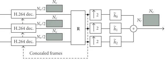
Figure2: Block diagram of the proposed decoder.
one slice results in a limited number of contiguous lost coeffi -cients in each column, hopefully permitting error recovery. It is easy to see that the slice organization of H.264/AVC implies that the loss of a single packet gives rise to the loss of a rect-angular region in one video frame of a subsequence, whose dimensions is equal to the dimensions of a slice. Since we are applying the filter bank columnwise, a loss of a rectangle of coefficients will look like a loss ofShconsecutive coefficients, whereShis the slice height. In other words, the synthesis filter bank will experience losses in bursts whose length is a multi-ple ofSh.
On the receiver side (Figure 2), the video streams are independently processed by H.264/AVC synchronized de-coders. In [12,13], a practical algorithm for dual frame com-putation with low delay and reduced complexity is presented. The scheme of [12,13] puts in front of the synthesis block a restoration stagewhich recovers, whenever possible, the miss-ing coefficients from the received ones, “hiding” the losses from the synthesis filter bank. The decoders are therefore connected to a restoring blockR, which recovers channel er-rors by implementing the algorithm of [12,13] whenΦI is still a subframe. In this case, the cascade of the restoring pro-cedure with the original dual filter bank is indeed equiva-lent to the dual of the lossy frame operatorΦI. We remark that this solution needs only local information and does not introduce any relevant delay in the decoding process. More-over, the computational complexity is reasonable, since it ba-sically requires the inversion of a matrix with dimension cor-responding to the number of lost coefficients in a column (see [12,13] for a detailed discussion). When slices are lost in the same position in two out of three descriptions, ΦI becomes incomplete and missing regions have to be recov-ered using an approximate concealment technique. In par-ticular, we interpolate one missing systematic channel from the correctly received stream using bilinear interpolation, then feed these two subimages to the usual restoring block.1 This typically gives acceptable results, due to the high spatial correlation among descriptions in the proposed scheme. In Section 4we will see a temporal interpolation technique that slightly improves reconstructed video quality in case of in-completeΦI. Another important aspect in using the H.264
1When two channels out of three are received,Φ
Iis indeed a frame.
codec is to avoid error propagation due to direct-mode pre-diction [10]. If a reference frame (e.g., a P frame) is lost, B slices coded in direct mode cannot be decoded, even if the data relative to the B frame are received correctly. The so-lution we adopt is to mark B blocks as lost when they are coded in direct mode with respect to corrupted reference in-formation, and to treat them as those lost because of channel failures.
The output of the restoring block, with concealment in case of unrecoverable errors followed by application of the algorithm of [12,13], is a set of three recovered subframes with dimensionNr/2×Nc. These subframes are then fed into the synthesis filter bank, whose output is an approximation of the original full-size sequence. Recovered subframes for each description are copied into the corresponding decoder frame buffer, in order to limit error propagation from refer-ence frames due to interframe coding.
3.1. System design
In order to make the scheme ofFigure 1effective, it is nec-essary to design the third filterh2. As anticipated,h2 must be a lowpass filter since its output must be a compressible sequence. Moreover,h2must be such that the filter bank in Figure 1is DFIR and such that the lower bound resulting af-ter the loss of one packet is as large as possible.
In this section, we solve this problem by presenting a general analysis and providing results for the solution of the following problems which generalize the problem of design-ingh2.
(1) Given an orthogonal filter bank withMchannels, we want to add a redundant channel so that the resulting filter bank is doubly FIR.
(2) We want to design a systematic (M+ 1)/MDFIR filter bank so that the lower bound of subframeΦresulting after losses is as large as possible. When losses occur, we implicitly analyze the signal with a frame with a smaller lower bound, and this may cause quantization error enhancement accord-ing to (4).
error according to (4). The bounds are written as a function of the polyphase components of the (M+ 1)th redundant channel filter, so they can be used for the filter choice or de-sign. We take into account the case ofLconsecutive coeffi -cients lost in a channel. This hypothesis derives from the fact that we are considering a framework where coefficients from each channel are grouped into packets, and a packet loss cor-responds to a set of consecutive coefficients missing at the receiver.
3.1.1. Doubly FIR filter banks
In detail, we will analyze the following problem.
Problem 1. Lethj,j=0,. . .,M−1, be the impulse responses of an orthogonalM/M FIR filter bank. Find a filterg such that the resulting (M+ 1)/Mfilter bank is a doubly FIR filter bank.
The solution toProblem 1is contained in the following theorem.
Theorem 1. Lethj,j=0,. . .,M−1, andgbe as inProblem 1.
The filter bank made ofhj,j =0,. . .,M−1, andgis doubly
FIR if and only if
n
g(n)g(n−Mk)= g2δ(k), ∀k∈Z, (7)
that is, if and only ifg is orthogonal to its own translations of multiples ofM.
Proof. Letgk(n)=g(k+nM) be thekth polyphase compo-nent ofgand letGk(z) be itsz-transform. The polyphase ma-trix relative to the new filter bank is
K(z)= G H(z)
0(z) G1(z)· · ·GM−1(z)
= GH(z)t(z)
, (8)
whereH(z) is the polyphase matrix of the orthogonal filter bankh0,. . .,hM−1, andGt(z)=
G0(z) G1(z)· · ·GM−1(z)
is the transpose of the vector of the z-transforms of the polyphase components ofg. According to Cvetkovi´c and Vet-terli [16] the extended filter bank is doubly FIR if and only if
r(z)detKtz−1K(z)=αz−k, ∃α∈C,k∈Z. (9) By observing that
rz−1=detKt(z)Kz−1=detKtz−1K(z)t=r(z), (10)
it follows that (9) is true if and only ifr(z) is a constant. With some algebra and by exploiting well-known results about de-terminants [17], one can write
r(z)=detHtz−1H(z) +Gz−1Gt(z)
=detI+Gz−1Gt(z)
=1 +Gt(z)Gz−1=1 +
M−1
k=0 Gk
z−1G
k(z). (11)
It is clear that (11) is a constant if and only ifr(z)−1 =
M−1
k=0 Gk(z−1)Gk(z) is. Observing that r(z) −1 is the z-transform of the sampled version of the correlation ofg, it follows thatr(z) is a constant, and the filter bank is doubly FIR, if and only if (7) is true, that is,g is orthogonal to its own translations.
A consequence ofTheorem 1is that, ifM =2, the only possible filter with linear phase resulting in a doubly FIR fil-ter bank is the 2-tap Haar filfil-ter [18]. If we consider a system-atic filter bank, as we will do in the proposed video coding scheme, this implies to work blockwise. More precisely, the filter bank is equivalent to mapping each pair of consecutive samples into the triple made of the two samples and their average.
If linear phase is necessary, as in image and video cod-ing applications, and one does not want to work blockwise, the dual filter bank will necessarily have IIR impulse re-sponses. In this case, if the decay of the impulse responses of the resulting IIR filters is fast enough, the dual filters can be approximated with possibly short FIR filters, for example, by truncation of the filter kernels. The corresponding DFIR filter bank introduces a small error in the reconstruction pro-cess which can be negligible in coding applications. The sit-uation is similar to what happens for nearly perfect recon-struction orthogonal filter banks, where linear-phase filters can be used at the expense of a small error in the reconstruc-tion [14].
3.1.2. Reconstruction error in response to packet losses
The second problem we consider is the design of the redun-dant channel filter in a systematic filter bank to allow for a “good” reconstruction even in presence of packet losses. This means that the lower bound ofΦImust be as large as pos-sible. As mentioned, we take into account the case ofL con-secutive coefficient losses in each channel. We will therefore analyze the lower bound ofΦIwhen a set ofLconsecutive coefficients is lost in a single channel.
Property 1. Lethj,j=0,. . .,M, be the impulse responses of an (M+ 1)/Msystematic filter bank and let
yj(n)=
m
x(m)hj(Mn−m). (12)
Let 0≤c≤Mand suppose that a burst ofLcoefficients of thecth channel, that is, coefficientsyc(n),n=0,. . .,L−1, are lost. LetΦI andAIbe the corresponding subframe and its lower bound, respectively.
Then, ifc=M, we haveAI=1; otherwise
minωHc,M
ejω2 1 +T+ 2√T
≤AI
≤ 2
Nc−1
hc,M21
L + minω Hc,M
ejω2L−Nc+ 1
L .
In (13),Nc is the length ofhc,M(n) = hM(c+nM), thecth polyphase component ofhM, whileT is the 1-norm of the autocorrelation of filterhMsampled with a factorM, namely,
T
n∈Z
r(n)= r1, r(n) m
hM(m)hM(m−Mn).
(14)
The proof for the upper bound is reported in the ap-pendix,Proof A.1, while the proof for the lower bound is in the appendix,Proof A.2.
Note that whenL Nc, the right-hand side of (13) is approximately equal to
min ω Hc,M
ejω2
. (15)
This suggests the following criterion to achieve a small recon-struction error in response to packet losses.
Criterion 1. Suppose bursts of coefficient losses are expected and lethMbe the (M+ 1)th filter of an (M+ 1)/Msystematic filter bank. ChoosehMsuch that
min
c∈{0,...,M−1}minω Hc,M
ejω2 (16)
is as large as possible.
3.2. MD 3 video codec: choice of the filter
From the results of Section 3.1, the filter for the redun-dant channel in the systematic filter bank under consider-ation should be chosen according to Criterion 1. We took into account the four- and eight-tap lowpass filters from the well known family of Daubechies filters [14] reported in Table 1. These two filters are orthogonal to their even translations, and therefore the resulting filter bank is exactly DFIR. We also considered a linear-phase redundant chan-nel filter. In the following, we will refer to this filter as the symmetric 4-tap filter (Table 1). The use of a linear-phase fil-ter can be useful for video coding purposes, also because it allows for symmetric rather than periodic signal extension in the analysis stage. Moreover, the symmetric filter was de-signed according toCriterion 1. As we will see, its perfor-mance is actually better than that of the 4-tap Daubechies filter and is comparable to that of the 8-tap Daubechies fil-ter. Since the symmetric filter is not orthogonal to its trans-lations, the hypotheses of Theorem 1 are not met exactly, and the resulting filter bank has IIR synthesis filters. These are very well approximated by the FIR filters ofTable 2. The impulse responses of the dual filter bank are truncated to make the system DFIR so that the overall reconstruction er-ror is negligible. In particular, it is easy to see that, when the input is modeled as a random process uniformly distributed in [0, 255], the cascade of the FIR analysis and synthesis fil-ter banks, with no quantization, allows for a peak signal-to-noise ratio (PSNR) of about 60 dB. The PSNR is defined as
PSNR10 log10255 2
MSE, (17)
where MSE is the mean squared reconstruction error with the input. The same reconstruction quality is obtained, with no quantization, with the video sequences we consider in Section 4.
Let us now consider the performance of the filters when losses and quantization are taken into account.Figure 3 com-pares the amplitude of the frequency responses of the two polyphase components of the 4-tap symmetric and Daub-echies filters. As we can see, the 4-tap DaubDaub-echies filter has a smaller minimum in the first polyphase component. From (16), we conclude that the symmetric filter should perform better than the 4-tap Daubechies filter. This will be con-firmed by the results in the experimental section.
4. EXPERIMENTAL RESULTS
In this section, we evaluate the performance of the proposed video coding scheme (MD 3) presented inSection 3. Orig-inal sequences are in CIF format. This scheme is compared with other two MD systems based on spatial subsampling of original frames. The first one (MD 4) originates four descrip-tions from the spatial polyphase components of the original frame. Each description, whose dimension is 1/4 of that of the original frame, is compressed independently, packetized, and sent over an error-prone network. The second scheme (MD 2) has a similar structure, but only two descriptions are generated by separating the even and odd rows of the orig-inal frame. We compare the MD schemes with a standard single-description (SD) H.264/AVC coder which includes ba-sic error concealment as described in [19]. The coders use the H.264/AVC test model software versionJM6.0a. To increase robustness to channel errors and make a fair comparison, the SD coder uses the random intra-macroblock refresh cod-ing option, that is, 100 macroblocks for every CIF frame are coded in intramode. No random intra-macroblock refresh coding option is activated in the MD schemes. Other coding options are the same for the SD and MD coders. In partic-ular the GOP structure is I BBBB P BBBB P BBBB P BBBB I, and slices have a fixed 1000-byte dimension. Each slice is sent as a packet, and each packet is lost according to a certain probability model.
For the MD 2 scheme and the MD 4 scheme, in case of errors in one or more descriptions, appropriate error concealment via bilinear interpolation from correctly re-ceived descriptions is performed at the receiver. Similarly to our scheme, corrected subframes are copied into the corre-sponding receiver frame buffers to limit error propagation. B blocks that use direct mode prediction with respect to lost P slices are also marked as lost. In case all the descriptions are lost, basic error concealment is applied as in [19] in all the MD coders, including the frame-based one.
Table1: Analysis filter banks for the symmetric 4-tap redundant channel filter, and the 4-tap and 8-tap Daubechies channel filters.
Symmetric 4-tap Daubechies 4-tap Daubechies 8-tap
n h0(n) h1(n) h2(n) h0(n) h1(n) h2(n) h0(n) h1(n) h2(n)
−2 0 0 −1.04·10−1 0 0 +3.42·10−1 0 0 +1.63·10−1
−1 0 1 +5.77·10−1 0 1 +5.92·10−1 0 1 +5.05·10−1
0 1 0 +5.77·10−1 1 0 +1.58·10−1 1 0 +4.46·10−1
1 0 0 −1.04·10−1 0 0 −9.15·10−2 0 0 −1.98·10−2
2 0 0 0 0 0 0 0 0 −1.32·10−1
3 0 0 0 0 0 0 0 0 +2.18·10−2
4 0 0 0 0 0 0 0 0 +2.33·10−2
5 0 0 0 0 0 0 0 0 −7.49·10−3
Table2: Synthesis filter banks for the symmetric 4-tap redundant channel filter, and the 4-tap and 8-tap Daubechies channel filters.
Symmetric 4-tap Daubechies 4-tap Daubechies 8-tap
n h0(n) h1(n) h2(n) n h0(n) h1(n) h2(n) n h0(n) h1(n) h2(n)
−6 +1.09·10−4 0 +1.24·10−4 −3 +2.08·10−2 0 0 −7 +8.14·10−4 0 0
−5 −1.68·10−4 +1.09·10−4 −1.91·10−4 −2 −3.61·10−2 0 0 −6 −2.53·10−3 0 0
−4 +1.52·10−3 −9.89·10−4 +1.74·10−3 −1 −1.25·10−1 +3.61·10−2 −6.10·10−2 −5 −1.40·10−4 +2.53·10−3 −5.00·10−3
−3 −2.35·10−3 +1.52·10−3 −2.68·10−3 0 +9.06·10−1 −6.25·10−2 +1.06·10−1 −4 +7.45·10−3 −7.84·10−3 +1.55·10−2
−2 +2.14·10−2 −1.39·10−2 +2.43·10−2 1 −6.25·10−2 +7.61·10−1 +3.94·10−1 −3 −5.00·10−3 −7.45·10−3 +1.45·10−2
−1 +5.70·10−2 +2.14·10−2 −3.75·10−2 2 −3.61·10−2 −1.25·10−1 +2.28·10−1 −2 −7.06·10−3 +4.49·10−2 −8.82·10−2
0 +7.99·10−1 −1.94·10−1 +3.41·10−1 3 0 +3.61·10−2 0 −1 −4.70·10−2 +7.06·10−3 −1.32·10−2
1 −1.94·10−1 +7.99·10−1 +3.41·10−1 4 0 +2.08·10−2 0 0 +8.38·10−1 −1.52·10−1 +2.97·10−1
2 +2.14·10−2 +5.70·10−2 −3.75·10−2 5 0 0 0 1 −1.52·10−1 +8.29·10−1 +3.37·10−1
3 −1.391·10−2 +2.14·10−2 +2.43·10−2 6 0 0 0 2 −7.06·10−3 −4.70·10−2 +1.09·10−1
4 +1.52·10−3 −2.35·10−3 −2.68·10−3 7 0 0 0 3 +4.49·10−2 +7.06·10−3 0
5 −9.89·10−4 +1.52·10−3 +1.74·10−3 8 0 0 0 4 +7.45·10−3 −5.00·10−3 0
6 +1.09·10−4 −1.68·10−4 −1.92·10−4 9 0 0 0 5 −7.84·10−3 −7.45·10−3 0
7 0 +1.09·10−4 +1.24·10−4 10 0 0 0 6 −2.53·10−3 −1.40·10−4 0
8 0 0 0 11 0 0 0 7 0 +2.53·10−3 0
9 0 0 0 12 0 0 0 8 0 +8.14·10−4 0
be spent to code the parity-check video sequence. However, exact recovery within frame theory is possible when losses are not too numerous. One has to resort to approximate interpo-lation solutions only when the received information corre-sponds to an incomplete system. We will see in the following that, in the presence of packet losses, MD 3 has the best over-all performance. Moreover, the visual quality obtained with the proposed scheme is superior, because of the exact recov-ery capability for most error patterns.
4.1. Comparison of the filters
We start by considering the redundant channel filter choice in the proposed MD 3 scheme. The simulations we present here are relative to 100 frames of the CIF sequenceForeman.
Results are averages of 50 independent transmission trials, where packets are lost independently with probabilityP.
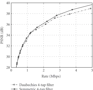
Figure 4compares the PSNR of the reconstructed video with the two filters and withP =0.1. The symmetric filter outperforms the Daubechies 4-tap filter by about 0.5 dB at high bit rates. The performance of the 8-tap Daubechies filter is indeed similar to that of the symmetric 4-tap filter.
1 0.8 0.6 0.4 0.2
|
H1
,
3
(
e
jω
)
|
0 0.1 0.2 0.3 0.4 0.5 0.6 0.7 0.8 0.9 1
ω/(2π) Daubechies 4-tap filter Symmetric 4-tap filter
(a) 1
0.8 0.6 0.4 0.2
|
H2
,
3
(
e
jω
)
|
0 0.1 0.2 0.3 0.4 0.5 0.6 0.7 0.8 0.9 1
ω/(2π) Daubechies 4-tap filter Symmetric 4-tap filter
(b)
Figure3: Amplitude of the frequency response of the polyphase components of the Daubechies 4-tap filter and of the symmetric 4-tap filter. (a) First polyphase component. (b) Second polyphase component.
frame even rows are missing at the receiver. As it can be seen fromFigure 5(a), using the 4-tap Daubechies filter leads to a granularity effect due to relevant quantization error en-hancement. This annoying effect is particularly visible near edges and around the eyes, where the coding error is greater. The effect disappears inFigure 5(b)corresponding to the use of the symmetric 4-tap filter.
4.2. Comparison of the MD coders
We compare here the performance of the proposed MD 3 scheme, adopting the symmetric 4-tap filter, with that of the SD, MD 2, and MD 4 schemes. The original video sequences are in CIF format, and the results are relative to 100 frames, averaged over 50 independent transmission trials. Packets are lost independently with probability P. Figures 6,7, and8 show the performance of the coders for the video sequences News, Foreman, andTeeny, respectively. TheNewssequence is characterized by low motion and a dark uniform back-ground, whereas theTeenysequence is characterized by large motion. Coding is performed for the same H.264/AVC QP values (QP = 19, 20,. . ., 41), therefore different compres-sion rates are obtained as a result of sequence motion con-tent.
Despite the fact that the SD coder can exploit spatial re-dundancy more efficiently, it does not have the best perfor-mance even forP =0, due to the intra-refresh coding op-tion. Nonetheless, the performance of the SD coder drops
40 38 36 34 32 30 28
PSNR
(dB)
0 1 2 3 4 5
Rate (Mbps) Daubechies 4-tap filter Symmetric 4-tap filter
Figure4: Rate-distortion comparison between the Daubechies 4-tap filter and the symmetric 4-4-tap filter adopted in this work.P=
0.1.
very rapidly for increasingP. We expect that the MD coder with four descriptions presents good robustness to errors from a subjective quality point of view, at the expense of some coding inefficiency. The proposed frame-based coder adds 1.5 redundancy to the video stream, and has therefore a low coding efficiency but possibly good robustness to er-rors from both a subjective and objective quality point of view. Note that, with no coding, perfect reconstruction is still possible in this case even in the presence of errors. Finally, the MD coder with two descriptions has better coding efficiency but possibly worse performance in terms of subjective qual-ity, since packet losses have to be corrected with the interpo-lation of entire rows.
It can be seen from Figures6and7that for loss proba-bilityP =0.05, the proposed frame-based MD scheme per-forms better than the SD scheme and the MD scheme with four descriptions. Moreover, at relatively high bit rates, the proposed scheme has the best performance of all schemes. ForP=0.1, the advantage of the proposed solution is even more evident. For theTeenysequence (Figure 6), the frame-based MD 3 system and the MD 4 system show comparable performance which are significantly better than that of MD 2. The intrinsic error recovery capability of the proposed MD 3 scheme plays an important role for visual quality in all coding conditions.Figure 9(b)shows a detail of the recon-structed video streamForemancoded at about 1 Mbps when one description is lost. In Figure 9(a), we show the recon-structed frame for the MD scheme with two descriptions. It can be seen from the figure that the MD scheme with two de-scriptions can originate annoying artifacts, especially along diagonal edges.
(a) (b)
Figure5: Details of reconstructed frames for the MD 3 frame system, using (a) the Daubechies 4-tap filter and (b) the symmetric 4-tap filter adopted in this work.
channel is in the “good” state, then no packet is lost, while if it is in the “bad” state, then every packet is lost. The transition probabilities have been determined by fixing the packet error probabilityP and the mean error burst length. In the ex-periments we choosePequal to the loss probability used in the i.i.d. case to make comparisons easier. Figures10,11, and 12show the rate-distortion comparison of the MD schemes for different values ofP, with a mean error burst length of 4 packets (since a packet contains a row of macroblocks, a burst of length 4 causes the loss of approximately 22% of the image).
With all sequences, the proposed MD 3 frame-based scheme has the best performance at relatively high bit rates and packet error probability, making it an interesting tech-nique for many application scenarios. Moreover, we remark that, due to the recovery possible within the framework of frame theory, the visual quality of the proposed solution does not present the typical artifacts originated by interpolation.
4.3. Concealment using temporal information
We consider here an alternative approximate error conceal-ment technique based on temporal information. It is used in the MD 3 system only when recovery with the dual frame is not possible, that is, when a slice is lost in the same position in two out of three descriptions.
Consider for the moment the case when two out of three descriptions are lost in the MD 3 system. If the correctly received description is not intracoded, its blocks are pre-dicted from the content of the corresponding frame buffer. If this prediction is accurate (i.e., the prediction error is negligible), we can use motion information to predict blocks of lost descriptions using the motion vectors of the received subsequence. In other words, when the prediction error is negligible in the received subsequence, we trust the received motion vectors to predict the missing sequences from the corresponding frame buffers.
In case two out of three slices in the same position are lost, the proposed solution evaluates the MSE of the pre-diction error on the correctly received description, block by block. If this error is below a predefined threshold, the out-lined temporal prediction procedure is used to recover one of the missing systematic channels, otherwise spatial interpola-tion is used. Then the received and reconstructed subimages are fed to the restoring block as before.
The MSE threshold computation is based on the quanti-zation error introduced by the H.264 coder. The mean square error MSEQP corresponding to the H.264 quantization pa-rameter QP can be written as [10]
MSEQP0.15·2QP/3. (18)
The MSE threshold is assumed equal toα·MSEQP, withα= 3.2 Note that the H.264 adaptive prediction process is very accurate, and blocks as small as 4×4 pixels are predicted.
The described temporal error concealment procedure can of course be used also for the MD 2 and MD 4 schemes. Figure 13 shows the PSNR for the sequence Foreman and i.i.d. packet errors withP =0.1. The MD 2 scheme receives the greatest benefit from temporal interpolation, due to the fact that spatial interpolation alone performs poorly along the strong edges in the background ofForeman.Remember that the MD 3 scheme actually uses this interpolation proce-dure only whenΦIis incomplete, that is, only when a slice is lost in the same position in two out of three descriptions.
5. CONCLUSIONS
In this paper, we present a multiple-description video cod-ing scheme based on the extension, uscod-ing frame-based anal-ysis, of a filter bank that computes the spatial polyphase components of the input video frames. Each resulting video subsequence is then coded with a standard H.264 coder. A simple modification of the decoder allows to increase robustness to packet losses by exploiting the added redun-dancy by means of reconstruction via the dual frame. In the event of excessive errors, when the resulting frame op-erator becomes incomplete and no direct reconstruction is possible, bilinear spatial interpolation is used to recover necessary information. We also considered the case of an interpolation procedure which operates in the temporal do-main. A detailed analysis toward system design and evalua-tion of reconstrucevalua-tion error bounds was carried out.
The proposed scheme shows a remarkably good perfor-mance when errors come into play and it shows several ad-vantages. It permits good robustness to channel errors. Up
44 42 40 38 36 34 32 30 28
PSNR
(dB)
0 0.5 1 1.5 2
Rate (Mbps) SD
MD 4 desc.
MD 2 desc. MD frames 3 desc. (a)
44 42 40 38 36 34 32 30 28
PSNR
(dB)
0 0.5 1 1.5 2
Rate (Mbps) SD
MD 4 desc.
MD 2 desc. MD frames 3 desc. (b)
44 42 40 38 36 34 32 30 28
PSNR
(dB)
0 0.5 1 1.5 2
Rate (Mbps) SD
MD 4 desc.
MD 2 desc. MD frames 3 desc. (c)
Figure6: Rate-distortion comparison of SD and MD schemes for theNewsCIF sequence and different values ofP(i.i.d. channel).
(a)P=0.01. (b)P=0.05. (c)P=0.1.
44 42 40 38 36 34 32 30 28
PSNR
(dB)
0 0.5 1 1.5 2 2.5 3 Rate (Mbps)
SD MD 4 desc.
MD 2 desc. MD frames 3 desc. (a)
44 42 40 38 36 34 32 30 28
PSNR
(dB)
0 0.5 1 1.5 2 2.5 3 Rate (Mbps)
SD MD 4 desc.
MD 2 desc. MD frames 3 desc. (b)
44 42 40 38 36 34 32 30 28
PSNR
(dB)
0 0.5 1 1.5 2 2.5 3 Rate (Mbps)
SD MD 4 desc.
MD 2 desc. MD frames 3 desc. (c)
Figure7: Rate-distortion comparison of SD and MD schemes for theForemanCIF sequence and different values ofP(i.i.d. channel).
42 40 38 36 34 32 30 28 26
PSNR
(dB)
0 1 2 3 4 5
Rate (Mbps) SD
MD 4 desc.
MD 2 desc. MD frames 3 desc. (a)
42 40 38 36 34 32 30 28 26
PSNR
(dB)
0 1 2 3 4 5
Rate (Mbps) SD
MD 4 desc.
MD 2 desc. MD frames 3 desc. (b)
42 40 38 36 34 32 30 28
PSNR
(dB)
0 1 2 3 4 5
Rate (Mbps) SD
MD 4 desc.
MD 2 desc. MD frames 3 desc. (c)
Figure8: Rate-distortion comparison of SD and MD schemes for theTeenyCIF sequence and different values ofP(i.i.d. channel).
(a)P=0.01. (b)P=0.05. (c)P=0.1.
to relatively high packet loss probabilities (P 0.1 in our experiments), the intrinsic recovery capability of the frame based system can be exploited for most error patterns. As a
(a)
(b)
Figure9: Details of reconstructed frames for (a) the MD 2 system and (b) the frame-based MD 3 system when one description is lost.
matter of fact, as long as the probability of losing data in the same position in two out of three descriptions is low, the re-construction depends only on the quality of the individual descriptions. No artifacts are present in the reconstructed se-quences because losses can be completely recovered by means of the redundancy provided by frame analysis. For larger val-ues ofP, when only one description is received for a given image region, one has to resort to approximate interpola-tion techniques. Also, when no descripinterpola-tion is received, con-cealment can be done by using successive or past frames ac-cording to the basic SD error recovery procedures of H.264. In the latter two cases, the visual quality and the PSNR can drop significantly. This is particularly evident when the sub-sequences are coded with good quality and spatial interpola-tion does not provide an acceptable approximainterpola-tion, for ex-ample, when the image sequence has diagonal edges.
44 42 40 38 36 34 32 30 28
PSNR
(dB)
0 0.5 1 1.5 2
Rate (Mbps) MD 2 desc.
MD 4 desc. MD frames 3 desc.
(a)
44 42 40 38 36 34 32 30 28
PSNR
(dB)
0 0.5 1 1.5 2
Rate (Mbps) MD 2 desc.
MD 4 desc. MD frames 3 desc.
(b)
44 42 40 38 36 34 32 30 28
PSNR
(dB)
0 0.5 1 1.5 2
Rate (Mbps) MD 2 desc.
MD 4 desc. MD frames 3 desc.
(c)
Figure 10: Rate-distortion comparison of MD schemes for the
NewsCIF sequence and different values ofP (Gilbert channel).
(a)P=0.01. (b)P=0.05. (c)P=0.1.
42 40 38 36 34 32 30 28
PSNR
(dB)
0 0.5 1 1.5 2 2.5 3 Rate (Mbps)
MD 2 desc. MD 4 desc. MD frames 3 desc.
(a)
42 40 38 36 34 32 30 28
PSNR
(dB)
0 0.5 1 1.5 2 2.5 3 Rate (Mbps)
MD 2 desc. MD 4 desc. MD frames 3 desc.
(b)
42 40 38 36 34 32 30 28
PSNR
(dB)
0 0.5 1 1.5 2 2.5 3 Rate (Mbps)
MD 2 desc. MD 4 desc. MD frames 3 desc.
(c)
Figure 11: Rate-distortion comparison of MD schemes for the
ForemanCIF sequence and different values ofP(Gilbert channel).
42 40 38 36 34 32 30 28 26
PSNR
(dB)
0 1 2 3 4 5
Rate (Mbps) MD 2 desc.
MD 4 desc. MD frames 3 desc.
(a)
42 40 38 36 34 32 30 28 26
PSNR
(dB)
0 1 2 3 4 5
Rate (Mbps) MD 2 desc.
MD 4 desc. MD frames 3 desc.
(b)
42 40 38 36 34 32 30 28 26
PSNR
(dB)
0 1 2 3 4 5
Rate (Mbps) MD 2 desc.
MD 4 desc. MD frames 3 desc.
(c)
Figure 12: Rate-distortion comparison of MD schemes for the
TeenyCIF sequence and different values ofP(Gilbert channel).
(a)P=0.01. (b)P=0.05. (c)P=0.1.
44 42 40 38 36 34 32 30 28
PSNR
(dB)
0 0.5 1 1.5 2 2.5 3 3.5 Rate (Mbps)
MD 2,P=0 MD 2,P=0.01 MD 2,P=0.01 with opt. MD 2,P=0.05
MD 2,P=0.05 with opt. MD 2,P=0.10 MD 2,P=0.10 with opt. (a)
44 42 40 38 36 34 32 30 28
PSNR
(dB)
0 0.5 1 1.5 2 2.5 3 3.5 Rate (Mbps)
MD 4,P=0 MD 4,P=0.01 MD 4,P=0.01 with opt. MD 4,P=0.05
MD 4,P=0.05 with opt. MD 4,P=0.10 MD 4,P=0.10 with opt. (b)
44 42 40 38 36 34 32 30 28
PSNR
(dB)
0 0.5 1 1.5 2 2.5 3 3.5 Rate (Mbps)
MD 3,P=0 MD 3,P=0.01 MD 3,P=0.01 with opt. MD 3,P=0.05
MD 3,P=0.05 with opt. MD 3,P=0.10 MD 3,P=0.10 with opt. (c)
APPENDIX
PROOFS
For notation simplicity, we setg(n)hM(n), the redundant channel filter of a systematic (M+ 1)/Mfilter bank.
Proof A.1. We prove here the upper bound in (13). Consider first the casec=M, that is, only redundant coefficients are lost. In this case all the samples of x are received through the systematic channels and, obviously,FIx ≥ xwhich impliesAI≥1. We can obtainAI=1 by choosingx orthog-onal togand its translations of multiples ofM. This proves the claim forc=M.
In order to prove the claim forc=0,. . .,M−1, we will search for a specificxsuch thatFIx2/x2is not larger than the right-hand side of (13). This will prove the claim. Since we are searching forxsuch thatFIxis small, we choosex such thatx(n)=0 only whenn=c,c+M,. . .,c+ (L−1)M. With no loss, the output of channel c is identically zero, except for L consecutive coefficients. Indeed, we suppose that these coefficients are actually lost. With this choice, any nonnull received coefficient arrives through the redundant channel only. It is easy to see that
yM+1(n)=xcgc(n), (A.1)
wherexc(n)=x(c+nM) andgc(n)=g(nM−c) are thecth polyphase component ofxandg, respectively. Letω0be such that minω|Gc(ejω)| = |Gc(ejω0)|and choose
xc(n)=
expjω0n if 0≤n < L,
0 otherwise. (A.2)
Let Nc be the length of gc. Equation (A.1) implies that yM+1(n) = 0 only forn = 0,. . .,Nc+L−2 and it is easy to recognize that ifNc−1≤n≤L−1, then
yc(n)=Gc
ejω0expjω
0n
. (A.3)
By exploiting (A.3) one can write
Fx2=
Nc+L−2
n=0
xcgc(n)2
= Nc−2
n=0
xcgc(n)2 +
L−1
n=Nc−1 Gc
ejω0expjω
0n 2
+ Nc+L−2
n=L
xcgc(n)2
= Nc−2
n=0
xcgc(n)2
+ Nc+L−2
n=L
xcgc(n)2
+L−Nc+ 1Gc
ejω02.
(A.4)
By exploiting the well-known fact that |xcgc(n)| ≤ gc1xc∞ = gc1, one finds the following upper bound
to (A.4):
Fx2≤2N
c−1
gc2
1+
L−Nc+ 1Gc
ejω02.
(A.5)
By dividing (A.5) byx2 =L(see (A.2)) one obtains (13).
Proof A.2. To prove the lower bound in (13), we need the fol-lowing two lemmas, relating the frame bounds to the singular values of the analysis filter bank polyphase matrix.
Lemma A.1. LetHbe the polyphase matrix of anN/M anal-ysis filter bank and letσH(ω)be the smallest singular value of H(ejω). LetA
Hbe the lower bound of the corresponding frame
operatorF. The following equality holds: AH= inf
x=1Fx
2= min
ω∈[0,2π]σ 2
H(ω). (A.6)
Proof ofLemma A.1.Let H(ejω) = U(ω)S(ω)Vt(ω) be the singular value decomposition of H(ejω). The problem of searching for the lower bound ofFcorresponds to searching for an input signalxwithx =1 such that
Fx2=
N−1
j=0 yj2
(A.7)
is as small as possible, whereyjis the output of thejth chan-nel. By exploiting Parseval’s identity one can rewrite (A.7) as
Fx2=
N−1
j=0 2π
0
Yj(ω)2
dω=
2π
0
N−1
j=0
Yj(ω)2 dω
=
2π
0
Y(ω)2
dω=
2π
0
H(ejω)X(ω)2 dω,
(A.8)
where Y(ω) is the vector [Y0(ω),. . .,YN−1(ω)]t and X(ω) is the vector [X0(ω),. . .,XM−1(ω)]t of input polyphase component frequency transforms. It is well known that
H
ejωX(ω)2≥X(ω)2σH(ω)2. (A.9)
By exploiting (A.9) in (A.8) one obtains
Fx2≥
2π
0
X(ω)2
σH(ω)2dω. (A.10)
Formula (A.10) can be verified with the equality sign by choosing X(ω) proportional to the Mth column of V(ω), that is,
X(ω)=f(ω)VM(ω) (A.11)
for some function f : [0, 2π] → C. It is easy to see that x = 1 is equivalent to 02π|f(ω)|2dω = 1. With choice (A.11), (A.10) becomes
Fx2=
2π
0
f(ω)2
Letω0=argminω∈[0,2π]σH(ω). By exploiting (A.12) one can write
Fx2=
2π
0
f(ω)2
σH(ω)2dω
≥
2π
0
f(ω)2 σH
ω0
2 dω
=σH
ω0
22π
0
f(ω)2
dω=σH
ω0
2 .
(A.13)
Formula (A.13) shows that AH in (A.6) cannot be smaller than minω∈[0,2π]σH2(ω). It remains to show that for any>0 we can find f∈L2([0, 2π]),f =1, such that
2π
0 f 2
(ω)σH2(ω)dω≤σH2(ω) +. (A.14)
By exploiting the continuity ofσ2
H(ω), findδsuch that
ω−ω0< δ=⇒σ2
H(ω)−σH2
ω0
=σH2(ω)−σH2
ω0
≤. (A.15)
Let fbe such that f(ω)=0 if|ω−ω0| ≥ δand f(ω)= 1/√2δif|ω−ω0|< δ. It follows that
2π
0 f 2
(ω)σH2(ω)dω=
ω0+δ
ω0−δ
1 2δσ
2
H(ω)dω
≤
ω0+δ
ω0−δ
1 2δ σ2 H ω0 +dω
=σ2
H ω0 +. (A.16)
The following lemma allows to set a lower bound on the smallest singular value of a systematic filter bank polyphase matrixH.
Lemma A.2. LetHbe anyM×Mmatrix
H= U 0 at b
, (A.17)
where UtU = I anda ∈ CM−1,b ∈ C; and letσ
H be the
smallest singular value ofH. The following inequality holds:
σH2 ≥
|b|2
|b|2+a2+ 1 + 2a. (A.18)
Proof ofLemma A.2.First observe that one can always sup-poseU=Isince one can multiply (A.17) by diag(Ut, 1) and this does not change the singular values ofH. In order to find a lower bound to the smallest singular value of H, we will first search for an upper bound to the largest singular value of matrix of form (A.17). By applying such an upper bound to
H−1= ⎡ ⎢ ⎣
I 0
−at
b 1 b ⎤ ⎥ ⎦ (A.19)
and remembering thatσH is the inverse of the largest singu-lar value ofH−1we will be able to obtain the desired lower
bound.
As it is well known, the largest singular value of a ma-trix H is the matrix 2-norm H = supx=1Hx. Let x=[ut,v]t ∈CN be such thatx =1. The squared norm ofHxis
Hx2= ut,uta+bvt2= u2+|uta+bv|2
= u2+u2a2cos2φ+|b|2|v|2+ 2bvuta,
(A.20)
where φ is the angle between a andu. By observing that u ≤1,|v| ≤1, and
bvuta≤bvuta≤ |b||v|ua ≤ |b| a (A.21)
one can find an upper bound to (A.20):
Hx2≤1 +a2+|b|2+ 2|b| a. (A.22)
By applying (A.22) to (A.19) one obtains that the square of the largest singular value ofH−1is not larger than
μ=1 +a 2
|b|2 +
1
|b|2 +
2a
|b|2 =
|b|2+a2+ 1 + 2a
|b|2 .
(A.23)
Therefore, the square of the smallest singular value ofH is not smaller than
1
μ=
|b|2
|b|2+a2+ 1 + 2a. (A.24)
In order to prove the left-hand inequality in (13), we will show that the lower bound corresponding to losing all the coefficients of channel c cannot be larger than minω∈[0,2π]|Gc(ejω)|2/(1 +T + 2
√
T). If all the coefficients of channel care lost, subframe Φ corresponds to a frame obtained by means of anM/Mfilter bank whose polyphase matrixHis obtained from the original filter bank polyphase matrixKby deleting thecth row. According toLemma A.1, the lower bound of the frame operator corresponding toΦ is equal to minimum ofσ2
H(ω) whereσH(ω) is the smallest singular value ofH(ejω). By suitably permuting the column ofH(such an operation does not change the singular values) one can always bringHin the form
H(ω)= I 0 a(ω)t G
c
ejω
. (A.25)
By applyingLemma A.2to (A.25) one obtains that for each ω,
σH2(ω)≥
Gc ejω2
Gc
ejω2+a(ω)t2+ 1 + 2a(ω)t. (A.26)
Finally, in order to prove the claim, we need to find an upper bound for the denominator in (A.26). We have
Gc
ejω2+a(ω)t2= M−1
k=0 Gk
ejω2=R(ω),