Model 950
Maintenance
Manual
Document l2002l-00-A 27 February 1985
Copyright
Copyright (c) 1985 by TeleVideo Systems, Inc. All rights reserved. No part of this publication may be reproduced, transmitted, transcribed, stored in a retrieval system, or translated into any language or computer language, in any form or by any means, electronic, mechanical, magnetic, optical, chemical, manual, or otherwise, without the prior written permission of TeleVideo Systems, Inc., 550 East Brokaw Road, San Jose, California 95112.
DisclailDer
TeleVideo Systems, Inc. makes no representations or warranties with respect to this manual. Further, TeleVideo Systems, Inc. reserves the right to make changes in the specifications of the product described within this manual at any time without notice and without obligation of TeleVideo Systems, Inc. to notify any person of such revision or changes.
TeleVideo is a registered trademark of TeleVideo Systems, Inc. TeleVideo SystelDs, Inc., 550 East Brokaw Road, San Jose,
2. Ordering Spare Parts Regional Sales Offices
Terminal Division Spare Parts Price List Detachable Keycaps Part List
3. Installation and User's Guide
4. Theory of Operation
Main Logic Board Overview
CPU Timing and Control Display Controller
Video and Character Generation Visual Attributes
Input/Output Circuits Keyboard
Overview
Keyboard Layout Keyboard Interface Keyboard Scanning Basic Scan Routine
950 Gate Array Logic Board
Data Sheets
5. Schematics
6.
HOTEl A parts list follows the schematics and
silkscreens for each assembly.
PCB Assembly Control Board
PCB Assembly Control Board Gate Array
Video Monitor/Power SUP9ly Schematics and Parts List Video Monitor
Power Supply
Tube Specification Shock Hazard
TR Waveforms and Voltages PCB Assembly Video Monitor PCB Assembly Power Supply
7. Troubleshooting Guide
8. Bulletins and Addenda
iii
2-1 2-2 2-3 2-17
4-1 4-3 4-3 4-5 4-7 4-9 4-10 4-12 4-13 4-13 4-14 4-16 4-17 4-18 4-19
5-37 5-57
1. 2. 3. 4.
5-A. 5-B. 6.
7. 8. 9.
CPU Timing and Control Display Controller
Video and Character Generation
IIO Circuits
Keyboard Layout Keypad Layout
Keyboard X-Y Matrix Arrangement Keyboard Interface
8048 Ports 8048 Data Bus
Section 6
1. 2.
Spark Gaps
Discharging Voltages
iv
4-6 4-8 4-9 4-12 4-14 4-14 4-15 4-16 4-17 4-17
6-3
OEMs ("Buyer") that products manufactured by TeleVideo are free from defects in materials and workmanship. TeleVideo's obligations under this warranty are limited to repairing or replacing, at TeleVideo's option, the part or parts of the products which prove defective in material or workman-ship within one year after workman-shipment by TeleVideo.
Products may be returned to Buyer only after a Return Material Authorization number ("RMA") has been obtained from TeleVideo by telephone or in writing. Buyer will prepay all freight charges to return any products to the repair facility designated by TeleVideo and include the RMA number on the shipping container. TeleVideo will, at its option, either repair the defective products or parts or deliver replacements for defective products or parts on an exchange basis to Buyer, freight prepaid to the Buyer. Products returned to TeleVideo under this warranty will become the property of TeleVideo. With respect to any product or part thereof not manufactured by TeleVideo, only the warranty, if any, given by the manufacturer thereof, applies.
Exclusions
This limited warranty does not cover losses or damage which occur in shipment to or from Buyer, or are due to, (1) improper installation or maintenance, misuse, neglect, or any cause other than ordinary commercial or industrial application, or (2) adjustment, repair, or modifications by other than TeleVideo-authorized personnel, or (3) improper environment, excessive or inadequate heat-ing or air conditionheat-ing and electrical power failures, surges, or other irregularities, or (4) any statements made about TeleVideo's products by salesmen, dealers, distributors or agents, unless confirmed in writing by a TeleVideo officer.
If the firmware or hardware is altered or modified by the Buyer, this firmware and hardware is not covered within this limited warranty and the Buyer bears sole responsibility and liability for that firmware and hardware.
tHE FOREGOING TELEVIDEO LIMITED WARRANTY IS IN LIEU OF ALL OTHER WAR-RANTIES, WHETHER ORAL, WRIDEN, EXPRESSED, IMPLIED, OR STATUTORY. IMPLIED WARRANTIES OF MERCHANTABILITY AND FITNESS FOR A PARTICULAR PURPOSE DO NOT APPLY. TELEVIDEO'S WARRANTY OBLIGATIONS AND DISTRIBUTOR'S REMEDIES HEREUNDER ARE SOLELY AND EXCLUSIVELY AS STATED HEREIN.
TELEVIDEO'S LIABILITY, WHETHER BASED ON CONTRACT, TORT, WARRANTY, STRICT LIABILITY, OR ANY OTHER THEORY, SHALL NOT EXCEED THE PRICE OF THE INDIVIDUAL UNIT WHOSE DEFECT OR DAMAGE IS THE BASIS OF THE CLAIM. IN NO EVENT SHALL TELEVIDEO BE LIABLE FOR ANY LOSS OF PROFITS, LOSS OF USE OF FACILITIES OR EQUIPMENT, OR OTHER INDIRECT, INCIDENTAL, OR CONSEQUENTIAL DAMAGES.
Service Out of Warranty
If your terminal is out of warranty when it needs service, follow the same procedure to receive an RMA. You will be responsible for all shipping costs.
If your company requires a purchase order for out-of-warranty repairs, let us know the purchase order number when you call in. One purchase order may cover several repairs, but we will give each unit its own individual RMA number. This allows us to return each unit quickly without holding up the entire purchase order for one unit.
Extended Warranty
TeleVideo offers an Extended Warranty Agreement, which extends the terms of the above-stated Limited Warranty for an additional year. To take advantage of this Extended Warranty, you must sign the Extended Warranty Agreement and return it, together with full payment, to TeleVideo before the Limited Warranty expires. Shipping charges are not included in the Extended Warranty. This is normally the only expense you incur. Please contact the Customer Service department or your sales representative for details. To renew the Extended Warranty for another year, follow the same procedure.
in Sah Jose, California. The toll free numbers are 800/821-3774
(inside California) or 800/521-4897 (outside California). Please
have the purchase order number and TeleVideo part number ready
when you call. International customers can telex 910-339-9621,
attention Spares Order Entry.
Contract customers and institutions can order parts on a purchase order and be invoiced. All other customers must order parts on a C.O.D. or cash-in-advance basis.
All orders have a $50 minimum. Add 6.5 percent sales tax to
orders placed in California. Since we do not make any drop
shipments, please include the shipping and billing addresses with
your order. Shipments are Best Way, which is uPS. Although
special shipping requests will be accommodated, any extra costs incurred will be added to the invoice.
6900 Jericho Turnpike Suite 100 LL
Syosset, NY 11791 (516) 496-4777
west
18662 MacArthur Blvd. Suite t107
Irvine, CA 92715 (714) 476-0244
South
5525 High Point Drive Suite 1101
Irving, TX 75062 (214) 258-6776
Southeast
6075 The Corners Parkway Suite 1208
Norcross, GA 30092 (404) 447-1231
Northern Europe Dorna House,
Gui1dford Rd., west End Surrey GU249PW
England
Phone: 011-44-9-905-6464
Telex: 858922
2-2
1601 Trape10 Road Reservoir Place Waltham, MA Q2154
(617) 890-3282
Northwest
550 East Brokaw Road P.O. Box 6602
San Jose, CA 95150-6602 (408) 971-0255
Midwest
1002 E. Algonquin Suite 1112
Schaumburg, IL 60195 (312) 397-5400
Central Europe Saturnusstraat 25 2132 HB Hoofddorp The Netherlands
Phone: 011-31-2503-35444
Telex: 74615 TLVDO NL
Southern Europe 3 rue 1eCorbusier bat. Berne Si1ic 244 94568 Rungis Cedex, France
Phone: 011-33-686-4412
o®
TeleVideo Systems, Inc.
January 7, 1985
TERMINAL DIVISION SPARE PART PRICE LIST
DESCRIPTION
OPERATORS MANUALS INSTAL & USERS GUIDE PERSONAL TERMINAL INSTAL & USERS GUIDE 914
INSTAL & USERS GUIDE 924 INSTAL & USERS GUIDE 910 INSTAL & USERS GUIDE 910PLUS INSTAL & USERS GUIDE 912/920
INSTAL & USERS GUIDE 925 INSTAL & USERS GUIDE 950 INSTAL & USERS GUIDE 921 INSTAL & USERS GUIDE 925E INSTAL & USERS GUIDE 970 INSTAL & USERS GUIDE 970/50
INSTAL & USERS GUIDE 922
M1HNTENANCE MANUALS MAINTENANCE MANUAL 910/910PLUS
MAINTENANCE MANUAL 912/920
MAINTENANCE MANUAL 925 MAINTENANCE MANUAL 950 MAINTENANCE MANUAL 970 MAINTENANCE MANUAL 914 MAINTENANCE MANUAL 924 MAINTENANCE MANUAL 921 MAINTENANCE MANUAL 925E
MAINTENANCE MANUAL PERSONAL TERMINAL MAINTENANCE MANUAL 922
2-3
ijEW pIN
130624-00 130316-00 130903-00 120025-00 120046-00 120018-00 120035-00 120020-00 131961-00 131960-00 122446-00 130902-00 130906-00
120026-00 120019-00 120036-00 120021-00 130021-00 130623-00 130622-00 131967-00 131966-00 130825-00 130621-00
LIST PRICE
10.00 10.00 10.00 10.00 10.00 10.00 10.00 10.00 10.00 10.00 10.00 25.00 10.00
POWER SUPPLY MODULE 970 VIDEO MODULE
VIDEO MODULE 970
VIDEO MODULE PERSONAL TERMINAL VIDEO MODULE/POWER SUPPLY 914/924 LOGIC BOARD 910 TTL
LOGIC BOARD 910 G/A LOGIC BOARD 910PLUS TTL LOGIC BOARD 910PLUS G/A LOGIC BOARD 912/920B TTL LOGIC BOARD 912/920C TTL
LOGIC BOA.RD/POWER SUPPLY PERSONAL TERM. LOGIC BOARD 925 TTL
LOGIC BOARD 925 G/A LOGIC BOARD 950 TTL LOGIC BOA.RD 950 G/A
LOGIC BOARD 970 G/A (TTL Not Available) LOGIC BOARD 914
LOGIC BOARD 924 LOGIC BOARD 921 LOGIC BOARD 925E
KEYBOARD ASSEMBLY 910/910PLUS KEYBOARD ASSEMBLY 912B
KEYBOARD ASSEMBLY 912C KEYBOARD ASSEMBLY 920B KEYBOARD ASSEMBLY 920C KEYBOARD ASSEMBLY 914
KEYBOARD ASSEMBLY 924/925E/921 KYBD ASSEMBLY W/HOUSING 925/950 KYBD ASSEMBLY W/HOUSING 970
KEYBOARD ASSEMBLY PERSONAL TERMINAL TUBE B/W P4 12"
TUBE GREEN P31 12" TUBE GREEN P31 14" TUBE 9" CRT (AMBER) TUBE 12" CRT (AMBER)
DEMO PROGRAM EPROM 910 DEMO PROGRAM EPROM 910PLUS DEMO PROGRAM EPROM 925 DEMO PROGRAM EPROM 950 DEMO PROGRAM EPROM 970 DEMO PROGRAM EPROM 914 DEMO PROGRAM EPROM 924 DEMO PROGRAM EPROM PT CONVERSION KIT 910
CONVERSION KIT 910PLUS CONVERSION KIT 970/50 TTL
CONVERSION KIT 970/50 GATE ARRAY CONVERSION KIT CPIM WORDSTAR 925 CONVERSION KIT CPIM WORDSTAR 950 CURRENT LOOP KIT 910/910PLUS CURRENT LOOP KIT 925/924/914
MEMORY KIT 2ND PAGE 912/920
MEMORY KIT 2ND PAGE 925/950
MEMORY KIT 3RD 4TH PAGE 950 MEMORY KIT 2ND 3RD 4TH PAGE 950 MEMORY KIT 924
EMULATION KIT 925 (ADDS REGENT)
300/1200 BAUD MODEM PERSONAL TERMINAL 300 BAUD MODEM PERSONAL TERMINAL
HANDSET PERSONAL TERMINAL
CARRYING CASE PERSONAL TERMINAL 925E 2ND PAGE OPTION BOARD KIT 970 RS-422 INTERFACE
970 GRAPHICS MOUSE
ELECTRICAL COMPONENTS CAPACITORS CAP CERAMIC .02uF 50V
CAP CERMAIC 150pF 50V 100%
CAP CERAMIC 1.0pF 1KV SPARK GAP CAP CERAMIC 220pF 50V
CAP CERAMIC .01uF 50V CAP CERAMIC .01uF 16V 20% CAP CERAMIC 330PF 50V 20% CAP CERAMIC 3300uF 10V CAP CERAMIC .1uF 50V 10% CAP ELECTROLYTIC 1uF 10V
CAP ELECTROLYTIC (NON-P) 16uF 25V CAP ELECTROLYTIC 22uF 16V 20% CAP ELECTROLYTIC 10uF 16V +80% CAP ELECTROLYTIC 2.2uF 25V 10% CAP ELECTROLYTIC 22uF 16V 20% CAP ELECTROLYTIC 22uF 35V
180000-94 180000-73 180000-72 180000-74 180001-19 180001-91 180001-66 180002-18 121697-00 121691-00 130073-00 130649-00 122509-00 121874-00 121310-00 121311-00 120014-00 120015-00 120016-00 122317-00 132093-00 122499-00 130615-00 130617-00 130616-00 130810-00 132098-00 120870-00 130892-00 16.00 16.00 16.00 16.00 16.00 16.00 16.00 16.00 25.00 25.00 100.00 100.00 100.00 100.00 50.00 60.00 35.00 46.00 80.00 120.00 160.00 100.00 549.00 150.00 79.95 69.00 125.00 100.00 149.00
130186-00 .83 130138-00 .83 120309-00 2.35 121959-00 .83 130178-00 .83 120287-00 .83 120291-00 .83 130276-00 .83 120301-00 .83 122614-00 .83 122800-00 5.32 120257-00 .83 130176-00 .83
120265~00 .83
130189-00 .83 120261-00 .83 120269-00 2.39 120273-00 .83 CAP ELECTROLYTIC 4.7uF 35V 10%
CAP .ELECTROLYTIC 10uF 16V 20% *ALL GRAPHICS EMULATIONS MUST NOW *SPARE PARTS WILL NO LONGER CARRY
BE PURCHASED AS TOP ASSY'S. THE GRAPHICS EMULATIONS.
CAP ELECTROLYTIC 2.2KuF 10V 121962-00 2.62
CAP ELECTROLYTIC 2.2KuF 16V 130164-00 7.59
CAP ELECTROLYTIC 100uF 160V 121963-00 7.59
."-'tI
CAP ELECTROLYTIC 22uF 160V 121964-00 1.46
CAP ELECTROLYTIC 22uF 16V +20% 130175-00 .83
CAP ELECTROLYTIC 220uF 16V 121993-00 .83
CAP ELECTROLYTIC 220uF 25V 130127-00 .83
CAP ELECTROLYTIC 1000uF 16V 130185-00 .83
CAP ELECTROLYTIC 3.3KuF 35V 121965-00 7.45
CAP ELECTROLYTIC 3300uF 50V 130281-00 6.83
CAP ELECTROLYTIC 2000uF 35V 130275-00 3~73
CAP ELECTROLYTIC 4.7KuF 16V 121966-00 7.54
CAP ELECTROLYTIC 4.7uF 16V 121967-00 .83
CAP ELECTROLYTIC 47 uF 35V 130648-00 1.15
CAP ELECTROLYTIC 470uF 35V 121982-00 1.93
CAP ELECTROLYTIC 470uF 35V A/L+-20% 130211-00 1.40
CAP ELECTROLYTIC 3300uF 16V 130618-00 7.83
CAP ELECTROLYTIC 680 uF 16V 130584-00 .83
CAP ELECTROLYTIC 100uF 100V 130827-00 1.17
CAP DIP MICA 10pF 50V 5% 120241-00 .83
CAP MICA 20pF 50V 5% 120243-00 .83
CAP MICA 100pF 50V 5% 120247-00 .83
CAP MICA 47pF 50V 5% 120249-00 .83
CAP MICA 150pF 500V 1% 120251-00 .83
CAP MICA 330pF 500V 5% 120253-00 1.09
CAP MICA 390pF 500V 5% 120255-00 1.23
CAP MONOLYTHIC .01uF 50V 10% 120289-00 .83
CAP MONOLYTHIC 330pF 100V 20% 120293-00 .83
CAP MONOLYTHIC 22pF 50V +-10% AIL 130196-00 .83
CAP MONOLYTHIC 47pF 100V 5% 120295-00 1.24
CAP MONOLYTHIC 68pF 1KV 20% 120299-00 .83
CAP MONOLYTHIC .039uF 50V 10% 120303-00 .83
CAP MONOLYTHIC .039uF 50V 5% 120305-00 1.24
CAP MONOLYTHIC 100pF 100V 5% 120307-00 1.24
CAP MONOLYTHIC .1uF 50V +-5% 121868-00 .83
CAP MYLAR .1pF 100V 130169-00 .83
CAP MYLAR .047uF 50V 130168-00 .83
CAP MYLAR .0068uF 100V 5% 120281-00 .83
CAP MYLAR .0068uF 200V 121968-00 .83
CAP MYLAR .001uF 50V 121969-00 .83
CAP MYLAR .01uF 50V 121970-00 .83
CAP MYLAR .015uF 50V 5% 130139-00 .83
CAP MYLAR .033uF 400V 130126-00 .83
CAP MYLAR .039uF 50V 130145-00 .83
CAP MYLAR .47uF 50V 121971-00 .83
CAP MYJ .. AR .47uF 50V 121972-00 1.66
CAP MYLAR .47uF 100V 130188-00 3.24
CAP MYLAR .1uF 600V 121973-00 1.55
CAP MYLAR .1uF 800V 10% 130184-00 1.10
CAP MYLAR .47uF 400V 121975-00 2.14
CAP TANTALUM .22uF 35V 120285-00 .83
CAP TANTALUM .68uF 50V 120259-00 2.00
CAP TANTALUM 10uF 25V 10% CAP TANTALUM 4.7uF 16V 10% CAP TANTALUM 4.7uF 25V CAP TANTALUM .33uF 35V CAP GL PK 100F 25V +-20% CAP GL PK .1uF 25V +80% CAP GL PK 330pF 25V +80% CAP GL PK .01uF 25V +80% CAP GL PK 47 pF 50V
CAP GL PK 100pF 50V +-10%
CAP GL PK .001uF 25V +80/-20%
CAP GL PK 1500F 50V +-20% CAP AIL 3300uF 25V +-20%
120271-00 120275-00 130284-00 121981-00 130171-00 130172-00 130173-00 130174-00 130179-00 130183-00 130190-00 130202-00 130212-00
DIODES - REGULATORS - TRANSISTORS
DIODE ZENER IN759A/RD12EB DIODE ZENER IN747
DIODE IN914
DIODE IN920/KDS8513A DIODE IN4001
DIODE IN4004/DS-130TB
DIODE IN5391/DS135D
DIODE DSA17C/MR500
DIODE DS18/IDS135D
DIODE DSl13A/MRI-1000 DIODE LED MV55A RED DIODE P6KE
DIODE PLR 817 DIODE PFR 852
DIODE BY251 3A 200V DIODE SWITCH IN4148 DIODE ZENER 8.2V
DIODE 2AMP 100V BRIDGE
DIODE FAST RECOV RCTFIR lAMP 800V REGULATOR 79M12
REGULATOR LAS1512 REGULATOR LAS16CB
REGULATOR ~I-3122V
REGULATOR LM 317T 1.5A REGULATOR LAS1605
REGULATOR LAS1812 REGULATOR 78M05 REGULATOR 79L05AC REGULATOR 7912
REGULATOR SI-80506Z
REGULATOR SI-3052P/STR9005 924/914 IC101
TRANSISTOR 2N5320 PWR
TRANSISTOR HORIZ 60V KTC2233 T0220 TRANSISTOR 2N2219A
TRANSISTOR 2N2222A NPN/SILICON TRANSISTOR 2N2907A
TRANSISTOR 2SC983
TRANSISTOR 2N6121/2SCl173
TRANSISTOR 2N6124/2SA473
TRANSISTOR 2SC2373 TRANSISTOR KTC 1627A
TRANSISTOR 2N3904/KTC1815
TRANSISTOR KTC 2229Y TRANSISTOR KTC 1815Y TRANSISTOR KTA 1015Y TRANSISTOR KTC 200Y
FIRMWARE SYSTEM PROG EPROM PT 300 (U1)
SYSTEM PROG EPROM PT 1200 (U1) SYSTEM PROG EPROM 910
SYSTEM PROG EPROM 910PLUS SYSTEM PROG ROM 910
SYSTEM PROG ROM 912/920B (A49Bl) SYSTEM PROG ROM 912/920C (A49C1) SYSTEM PROG EPROM 925 A
SYSTEM PROG EPROM 925 B SYSTEM PROG ROM 950 (-OOlA) SYSTEM PROG ROM 950 (-007A) SYSTEM PROG EPROM 950 (043X) SYSTEM PROG EPROM 950 (044X) SYSTEM EPROM 970 G/A (U70) SYSTEM EPROM 970 G/A (U71) SYSTEM EPROM 970 G/A (U72) SYSTEM EPROM 970 G/A (U73) SYSTEM EPROM 924 AOOO (U14) SYSTEM EPROM 924 EOOO (U21) SYSTEM EPROM 970 TTL (A82) SYSTEM EPROM 970 TTL (A87) SYSTEM EPROM 970 TTL CA99) SYSTEM EPROM 970/950 (A82) SYSTEM EPROM 970/950 (A87) SYSTEM EPROM 970/950 (A99) SYSTEM EPROM 914 (U7)
33333M EPROM 921 (U7) SYSTEM EPROM 925E (U7) PROG MICROCOMPTR 8749
CHAR GEN EPROM 910/910PLUS
CHAR GEN ROM 910/910PLUS CHAR GEN ROM 912/920 (A3-2) CHAR GEN ROM 924 (U10)
CHAR GEN EPROM 925 CHAR GEN ROM 925
CHAR GEN ROM 950 (003A) CHAR GEN ROM 950 (002A) CHAR GEN EPROM US/UK 970
CHAR GEN ROM 914 (U19)
*
KYBD EPROM PRO 910/910PLUS (A2)*
KYBD ENCDR PRO 910/910PLUS (AI)180000-19 120532-00
*
These two parts are used together in a two chip setIC 74S00 IC 74LSOO IC 74LS03 IC 74S04 IC 74LS04 IC 74LS05 IC 74LS08 IC 74LS10 IC 74SL20 IC 74LS32 IC 74LS42 IC 74LS51 IC 74S74 IC 74H74 IC 74LS86 IC 74LSI09 IC 74LS139 IC 74LS145 IC 74LS157 IC 74LS163 IC 74LS166 IC 74LS173 IC 74LS174 IC 74LS253 IC 74LS367 IC 74LS373 IC 74LS374 IC 75188N/1488 IC 75189AN/1489 IC TILl17
IC NE555 IC DP8304 IC AMD2111-4A IC 2502HP
Ie TMS9927/5027 IC P8035
IC HIIG3 IC 7406 IC 4N38 IC 7414 IC 2114
IC 74LS245/N8T245N IC 74LS191
IC 74LS273 IC 74S240
INTEGRATED CIRCUITS
IC 93S16PC IC 74LS138 IC 74LS02 IC 74LS241 IC Al-126LS31 IC AM26LS32 IC 74LS240 IC 74LS244 IC 74S174 IC 74LS14 IC 74LS164 IC 14040B
IC 6116 STATIC RAM 2Kx8 150ns IC 6502A
IC 6545 IMHz IC 6551 IMHz IC 6522A
IC Z80A 810/2
IC Z80A CTC IC Z80A CPU IC Z80A DMA IC 68B045 2 MHz IC SY6551A-l 2MHz IC SY6545A-l 2MHz
IC 910/910 PLUS GATE ARRAY (1M!) IC 924 GATE ARRAY A
IC 924 GATE ARRAY B IC 925 GATE ARRAY (IMI) IC 950 GATE ARRAY A (A34) IC 950 GATE ARRAY B (A37) IC 74LSl12
IC 74S251
IC 2K BY 8 CMOS STATIC RAM IC 4116 16K DRAM
IC 9007 CRTC
IC 9006-135 BUFFER IC 2681 DUAL UART IC 2673 ATT CONT IC 2672 CRT CONT IC 9212 BUFFER
IC 970 G/A A (KIT)
IC G/A 970 B
IC G/A 970 C
IC G/A PERSONAL TERMINAL
IC G/A 914/925/910 (AMI) IC 74166 8BIT S.R.
IC 74LS74 2XD TYPE EDG-TRIG FIF
IC 6845R CRT CNTRL 910/914/925
IC NS455 VIDEO CPV TMP
RES CF 270 OHM 1/4W 5% RES CF 330 OHM 1/4W 5% RES CF 470 OHM 1/4W 5% RES CF 510 OHM 1/4W 5% RES CF 560 OHM 1/4W 5% RES CF 1K OHM 1/4W 5% RES CF 10K OHM 1/2W 5% RES CF 1.8K OHM 1/4W 5% RES CF 3.3K OHM 1/4W 5% RES CF 3.9K OHM 1/4W 5% RES CF 4.7K OHM 1/4W 5% RES CF 5.6K OHM 1/4W 5% RES CF 12K OHM 1/4W 5% RES CF 180 OHM 1/4W 5% RES CF 1M OHM 1/4W 5% RES CF 820 OHM 1/2W 5% RES CF 390 OHM 1/2W 5% RES CF 750 OHM 1/4W 5% RES CF 1.2K OHM 1/4W 5% RES CF lOOK OHM 1/4W 5% RES CF 51K OHM 1/4W 5% RES CF 22 OHM 1/4W 5% RES CF 47K OHM 1/4W 5% RES CF 150 OHM 1/4W 5% RES CF 10K OHM 1/4W 5% RES CF 200 OHM 1/4W 5% RES CF 220 OHM 1/4W 5% RES CF 33 OHM 1/4W 5% RES CF 100 OHM 1/4W 1% RES CF 51 OHM 1/4W 5% RES CF 22K OHM 1/4W 5% RES CF 27K OHM 1/4W 5% RES CF 47 OHM 1/4W 5% RES CF 2.7K OHM 1/4W 5% RES CF 90 OHM 1/4W 5% RES CF 91 OHM 1/4W 5% RES CF 2.2K OHM 1/4W 5% RES CF 3.9K OHM 1/4W 5% RES CF 6.8K OHM 1.4W 5% RES CF 30K OHM 1/4W 5% RES CF 56K OHM 1/4W 5% RES CF 82 OHM 1/4W 5% RES CF 220 OHM 1/4W 5% RES CF 680 OHM 1/4W 5% RES CF 2K OHM 1/4W 5% RES CF 22 OHM 1/2W 5% RES PACK 1K OHM SIP 10% RES PACK 6.2K OHM SIP 10% RES PACK 10K OHM SIP 5% RES PACK 4.7K OHM SIP 10% RES PACK 4.7K OHM 8 PIN SIP RES PACK 1K OHM SIP 5%
120513-00 120515-00· 120517-00 120519-00 120375-00 120521-00 121768-00 120523-00 120527-00 120339-00 120531-00 130136-00 130137-00 120533-00 120315-00 121770-00 121861-00 120317-00 120319-00 120321-00 120323-00 120335-00 120337-00 120339-00 120341-00 120343-00 120403~00 120345-00 120349-00 120361-00 120363-00 120373-00 120377-00 120383-00 121776-00 120385-00 120387-00 121774-00 120391-00 120393-00 120395-00 121440-00 120403-00 120371-00 120369-00 130194-00 120405-00 120407-00 120411-00 120413-00 120429-00 120427-00 2-11 .83 .83 .83 .83 .83 .83 .83 .83 .83 .83 .83 .83 .83 .83 .83 .83 .83 .83 .83 .83 .83 .83 .83 .83 .83 .83 .83 .83 .83 .83 .83 .83 .83 .83 .83 .83 .83 .83 .83 .83 .83 .83 .83 .83 .83 .83
RES CF 510 OHM 1/2W 5% RES CF 220 OHM 1/2W 5% RES CF 390 OHM 1/2W 5% RES CF 820 OHM 1/2W 5% RES CF 1.5K OHM 1/2W 5% RES CF 10K OHM 1/2W 5% RES CF 2.2M OHM 1/2W 5% RES WW 0.4 OHM 2W 10%
RES WW 0.6 OHM 2W
RES WW 0.4 OHM 2W 5%
RES WW 37.40 OHM 1/2W 1%
RES CF 3.9K OHM, 1/4W, 5% RES CF 13K OHM, 1/4W, 5%
POT BRIGHTNESS & VERTICAL HEIGHT POT VERTICAL LINEARITY
POT VIDEO B+ POT FOCUS POT CONTRAST POT CONTRAST
POT TRIM lOOK OHM TOP-ADJ PCMT POT TRIM 2K OHM TOP-ADJ PCMT
TRANSFORMERS/COILS
YOKE ASSY. PERSONAL TERMINAL TRANSFORMER FLYBACK KFS-00093 TRANSFORMER FLYBACK 970/914/924 TRANSFORMER HORIZ DR HDT19
TRANSFORMER POWER W/CON CRT858 TRANSFORMER POWER 970
TRANSFORMER BALUN TRANSFORMER 924
TRANSFORMER PERSONAL TERMINAL
TRANSFORMER FLYBACK PERSONAL TERMINAL COIL 1.4uH 5%
COIL 200uF 5%
COIL INDUCTOR 27uH .3PIE COIL LINEARITY ADJUSTABLE COIL LINEARITY NON ADJUSTABLE COIL DEFLECTION YOKE W/CONN COIL WIDTH 9 MHz
UPGRADE YOKE 970 YOKE DEFLECTION
YOKE DEFLECTION KYS 00060 COIL LINEAR 52mh
COIL WIDTH 10 UH +40%
120451-00 121860-00 121766-00 121862-00 121863-00 121864-00 121865-00 130195-00 121771-00 130197-00 130192-00 120389-00 130193-00 121777-00 121778-00 121779-00 121801-00 121802-00 121551-00 120441-00 120445-00 130836-00 122013-00 122690-00 122012-00 122011-00 122256-00 121866-00 130059-00 130225-00 130226-00 122689-00 122688-00 122010-00 122136-00 122009-00 122008-00 130135-00 132094-00 123551-00 130794-00 130134-00 130838-00 CRYSTALS/FUSES/BATTERIES
CRYSTAL 12.00 MHZ CRYSTAL 16 MHZ OSC
CRYSTAL 8.0000 MHZ CRYSTAL 13.6080 MHZ CRYSTAL 13.7931 MHZ CRYSTAT.J 23.814
CRYSTAL 21.2544 MHz OSC CRYSTAL 13.4784 MHz CRYSTAL 22.2912 MHZ CRYSTAL 23.8140 MHZ CRYSTAL 3.6864 MHZ FUSE 4A 125V
FUSE 3A 125V FUSE 1A 250V
FUSE 4A 3AG 250V SLO.BLO FUSE 3A 3AG 250V SLO.BLO POWER ADAPTER PATTERN GEN
SPEAKER wI CONNECTOR
THERMISTER SDT-100
FILTER AC LINE, 3 AMP, PT
FILTER AC LINE, 3 AMP, 910,912,950 TRANSDUCER AUDIO KYBD 970,924,914 BATTERY 970
BATTERY 924
BATTERY 970 COIN TYPE
ANGLE ADJUST(SCREEN TILT MECHANISM) SHIELD FLY TRANSFRMR SCREW TYPE 925
MECHANICAL COMPONENTS
TOP CASE 910/912
TOP CASE 920
TOP CASE 925/950
TOP CASE KEYBOARD 925/950
BOTTOM CASE 910/912/920
BOTTOM CASE 925/950
BOTTOM CASE KEYBOARD 925/950
BEZEL TOP CASE 925/950
BEZEL KEYBOARD 925/950
HOUSING ARM ASSEMBLY 970 HOUSING CRT 970
HOUSING MAIN ELECTRONIC 970
CASES
HOUSING KYBD TOP WIPALM REST 970 HOUSING KYBD BOTTOM W/PALM REST 970 COVER BACK HOUSING CRT 970
COVER SIDE HOUSING LOGIC BOARD 970 BEZEL CRT 970
HOUSING BOTTOM 914/924
HOUSING TOP 914/924
BEZEL FRONT 914/924
PEDESTAL 914/924
BEZEL PERSONAL TERMINAL
CONNECTOR SHROUD PERSON.AL TERMINAL KEYCAPS* KEYCAP DG 1X1 BLANK
KEYCAP DG 1X1 SCULP BLANK 0 KEYCAP DG 1X1 SCULP BLANK -7 KEYCAP DG 1X1 SCULP BLANK +7 KEYCAP DG 1X1 SCULP BLANK +14 KEYCAP DG 1Xl-1/2 BLANK
KEYCAP DG 1Xl-1/2 SCULP BLANK +7
KEYCAP DG 1X2 SCULP BLANK 0 KEYCAP DG 1X8
KEYCAP DG 1X8 SCULP KEYCAP LG 1X1 BLANK
KEYCAP LG 1X1 SCULP BLANK 0 KEYCAP LG 1X1 SCULP BLANK -7 KEYCAP LG 1X1 LOW PRO BLANK
KEYCAP LG 1X1 LOW PRO SCULP BLANK KEYCAP LG 1Xl-1/4 BLANK
KEYCAP LG 1Xl-1/4 SCULP BLANK +7
KEYCAP LG 1Xl-1/2 BLANK
KEYCAP LG 1Xl-1/2 SCULP BLANK -7
KEY CAP LG 2X1 SCULP BLANK 0 KEYCAP LG "L" RETURN
KEYCAP LG "L" BLANK (RETURN) KEYCAP LG "L" SCULP RETURN
KEYCAP LG "L" SCULP BLANK (RETURN) KEYCAP BLACK 1X1 BLANK
KEYCAP BLACK 1Xl-1/2 BLANK
KEYCAP BLACK 1X8 KEYCAP TAN 1X1 BLANK KEYCAP TAN 1Xl-1/2 BLANK
KEYCAP WHITE BLANK 1X1 1.5 DEGREE
KEYCAP GRAY BROWN BLANK 1X1 1.5 DEGREE KEYCAP WHITE BLANK 1X1 2 DEGREE
KEYCAP WHITE BLANK 1X1 2.5 DEGREE KEYCAP WHITE BLANK 1X1 9 DEGREE
KEYCAP GRAY BROWN BLANK 1X1 9 DEGREE KEYCAP WHITE BLANK 1X1 10 DEGREE KEYCAP GRAY BROWN BLANK 1X1 10 DEGREE KEYCAP WHITE BLANK 1X2 10 DEGREE
KEYCAP GRAY BROWN 1.25X1 2.5 DEGREE KEYCAP GRAY BROWN BLANK 1X1 2 DEGREE KEYCAP GRAY BROWN BLANK 1X1 2.5 DEGREE KEYCAP GRAY BROWN BLANK 1.25X1 9 DEGREE KEYCAP WHITE BLANK 2X1 10 DEGREE
KEYCAP GRAY BROWN BLANK 2X1 2 DEGREE KEYCAP GRAY BROWN BLANK 1X2X2 2 DEGREE KEYCAP WHITE BLANK 1X9 10 DEGREE
KEYCAP LG. BLOCK/CONV L.P. 912C KEYCAP LG. PRINT LP 912C
130484-00 11.50
120658-00 1.15 121616-01 1.15 121619-00 1.15 121618-00 1.15 121617-00 1.15 120724-00 1.75 121618-01 2.94 122514-00 3.45 120774-00 2.28 120897-00 3.45 120730-00 1.15 121616-00 1.15 121619-01 1.15 120765-00 1.15 121621-01 1.15 120772-00 1.75 121618-02 2.81 120727-00 1.75 121619-02 2.94 122513-00 3.45 120771-00 2.14 120771-01 4.49 120894-00 3.17 121616-02 4.49 120537-00 1.15 120633-00 2.07 120775-00 3.11 120638-00 1.15 120636-00 1.73 130680-00 .83 130680-01 .83 130681-00 .83 130682-00 .83 130683-00 .83 130683-01 .83 130684-00 .83 130684-01 .83 130685-00 1.15 130686-00 1.15 130681-01 .83 130682-01 .83 130687-00 1.15 130688-00 1.15 130689-00 1.15 130690-00 1.73 130413-00 2.30 120766-00 1.15 120770-00 1.15 *PART NUMBERS FOR PRINTED KEYCAPS CAN
MAINTENANCE MANUAL OR THROUGH SPARES
BE OBTAINED IN YOUR ORDER ENTRY, TELEVIDEO.
KEYSWITCH - ALPHA LOCK SWITCH TOP ADJ 7 POS DIP SWITCH TOP ADJ 10 POS DIP SWITCH SIDE ADJ 10 POS DIP SWITCH PUSHBUTTON
SWITCH POWER ON/OFF SPST
SWITCH POWER SELECT DPDT
SWITCH ROCKER 5A 125V 3A 250V
SWITCH KYBRD LOCKING 910/912
SWITCH KYBRD MMNTRY 910/912
SWITCH KYBRD MMNTRY 914/924 FUTABA
SWITCH KYBRD ALPHA LOCK 914/924
SHIPPING CARTONS
CARTON SHIP W/FOAM 910/912/920
CARTON SHIP W/FOAM 925/950
CARTON SHIP W/FOAM 970
CARTON SHIP W/FOAM 914/924/921/925E
CARTON SHIP W/FOAM PERSONAL TERMINAL
121995-00 121742-00 121810-00 120968-00 120969-00 120973-00 120974-00 130808-00 121533-00 121534-00 130446-00 130447-00 122372-00 122373-00 122497-00 130114-00 130811-00 MECHANICAL/CONNECTORS/CABLES/SOCKETS
BATTERY HOLDER
CABLE ASY KEYBOARD 912/920
CABLE ASY KEYBOARD 910
CABLE ASY KEYBOARD 925/950
CABLE ASY KEYBOARD 970 CABLE ASY MODEM RJ11
CABLE ASSY CURRENT LOOP 925 CONNECTOR 2 PIN RT ANGLE CONNECTOR 2 PIN STR WAF CONNECTOR 5 PIN STR WAF CONNECTOR 10 PIN WIRE WRAP CONNECTOR 40 PIN HDR STRAIGHT CONNECTOR KEYBOARD PCB 26PIN
CONNECTOR KEYBOARD RJ11 925/950
CONNECTOR KEYBOARD RJ12 PCB 970 CONNECTOR KEYBOARD RJ12 KYBD 970 CONNECTOR RIGHT ANGLE RS232
CONNECTOR RIGHT ANGLE METAL RS232 CONNECTOR STRAIGHT RS232
CONNECTOR BLUE MOLEX MALE CONNECTOR BLUE MOLEX FEMALE CONNECTOR RED MOLEX MALE CONNECTOR RED MOLEX FEMALE CONNECTOR WHITE MOLEX MALE CONNECTOR WHITE MOLEX FEMALE
CONNECTOR 4P HDR RED (5P W/#2P OUT) CORD POWER 6' 3 PRONG CONN
CORD POWER 3PIN W/PLUG & CONN
EQL ASY SPACE BAR KEY GUIDE EQL ASY SPACE BAR KEYGUIDE ARM FOOT KEYBOARD 925/950
FOOT KEYBOARD 970 FUSE HOLDER CLIP
FUSE HOLDER PANEL MOUNT INSULATION PAD TRANSISTOR INSULATOR PAD CRYSTAL KNOB CONTRAST
KEYSTOPPERS 100ea PIVOTSHAFT MINIMUM 25 PLUG JUMPER 910/910PLUS RETAINER BALUN
SHIELD PLATE LOGIC BOARD 970 SHROUD CONN 910/912/920
SHROUD CONN MODEM 910/912/920 SHROUD CONN 925/950
SHROUD CONN MODEM 925/950 SPACER NYLON, PCB SNAP MTG SOCKET IC 14 PIN
SOCKET Ie 16 PIN SOCKET IC 18 PIN SOCKET IC 24 PIN SOCKET IC 28 PIN SOCKET IC 40 PIN
SOCKET IC 16 PIN LOW PROFILE SPRING CRT GROUNDING
THUMB WHEEL 970
FOOT RUBBER PERSONAL TERMINAL CONN 7P MALE MOLEX
CONN lIP MALE MOLEX CONN 5P MOLEX
CONN 3P MOLEX
120912-00 120964-00 121906-00 122127-00 121804-00 120972-00 121808-00 120997-00 121530-00 122238-00 121978-00 120983-00 121645-00 130005-00 121002-00 121002-01 121001-00 121001-03 121644-00 120984-03 120984-05 120984-00 120984-01 120984-04 120984-02 121746-01 122105-00 122188-00 130208-00 130288-00 130290-00 130820-00 130820-01
CABLE HARNESSES WITH CONNECTORS
POWER HRN ASSY 970 VIDEO HRN ASSY 970 POWER HRN ASSY 924 VID & PIS ASSY
HRN ASSY w/230-115 SWITCH 912
PIS HRN ASSY 910/912/920 VID HRN ASSY 910/912/920 VID & LGC HRN ASSY 925/950
piS & VID HRN ASSY 925/950 VID & CTRL BRD HRN ASSY PT
PRICES SUBJECT TO CHANGE WITHOUT NOTICE
122185-00 122191-00 130066-00 130535-00 130493-00 130551-00 130552-00 130547-00 130539-00 130845-00 2.07 3.14 .83 .83 .83 2.30 .83 1.17 .83 13.80 5.38 2.07 .83 69.00 25.88 25.88 25.88 25.88 1. 04 .90 .83 .95 1. 27 1.52 2.07 6.40 .83 1.66 .83 1.38 1.73 1.38 1. 38 22.49 6.21 13.80 2.82 1.16 7.73 16.48 15.18 8.00 8.83
Spare 9arts has a $50.00 minimum requirement on all part orders.
950 Detachable Keycaps
Description Stepped Keycaps Printed Blank Sculptured/Matted Keycaps Printed Blank Degrees/Rates
1X1 LIGHT GREY BLANK
---
120730-00---
121616-00 0 (1)1X1 LG NO SCROLLlsETUP 120755-00 120730-00 120887-00 121616-00 0
1X1 LIGHT GREY F1 120731-00 120730-00 120850-00 121616-00 0
1X1 LIGHT GREY F2 120732-00 120730-00 120851-00 121616-00 0
1X1 LIGHT GREY F3 120733-00 120730-00 120852-00 121616-00 0
1X1 LIGHT GREY F4 120734-00 120730-00 120853-00 121616-00 0
1X1 LIGHT GREY F5 120735-00 120730-00 120854-00 121616-00 0
1X1 LIGHT GREY F6 120736-00 120730-00 120855-00 121616-00 0
1X1 LIGHT GREY F7 120737-00 120730-00 120856-00 121616-00 0
1X1 LIGHT GREY F8 120738-00 120730-00 120857-00 121616-00 0
1X1 LIGHT GREY F9 120739-00 120730-00 120858-00 121616-00 0
1X1 LIGHT GREY FlO 120740-00 120730-00 120859-00 121616-00 0
1X1 LIGHT GREY F11 120741-00 120730-00 120860-00 121616-00 0
1X1 LG CHAR INSERT 120742-00 120730-00 120861-00 121616-00 0
N 1X1 LG CHAR DELETE 120743-00 120730-00 120862-00 121616-00 0
I
1X1 LG LINE INSERT 120744-00 120730-00 120863-00 121616-00 0
....
...1X1 LG LINE DELETE 120745-00 120730-00 120864-00 121616-00 0
1X1 DARK GREY BLANK
---
120658-00---
121617-00 +141X1 DG ESC/LOC ESC 120723-00 120658-00 120842-00 121617-00 +14
1X1 DARK GREY III 120659-00 120658-00 120778-00 121617-00 +14 (2)
1X1 DARK GREY 2/@ 120660-00 120658-00 120779-00 121617-00 +14
1X1 DARK GREY 3/t 120661-00 120658-00 120780-00 121617-00 +14
1X1 DARK GREY 4/$ 120662-00 120658-00 120781-00 121617-00 +14
1X1 DARK GREY 5/% 120663-00 120658-00 120782-00 121617-00 +14
1X1 DARK GREY 6/A 120664-00 120658-00 120783-00 121617-00 +14
1X1 DARK GREY 7/& 120665-00 120658-00 120784-00 121617-00 +14
1X1 DARK GREY 8/* 120666-00 120658-00 120785-00 121617-00 +14
1X1 DARK GREY 9/( 120667-00 120658-00 120786-00 121617-00 +14
1X1 DARK GREY 0/) 120668-00 120658-00 120787-00 121617-00 +14
1X1 DARK GREY -1_ 120669-00 120658-00 120788-00 121617-00 +14
1X1 DARK GREY =1+ 120670-00 !20658-00 120789-00 121617-00 +14
1X1 DARK GREY '1- 120671-00 120658-00 120790-00 121617-00 +14
1X1 DARK GREY \1 I 120672-00 120658-00 120791-00 121617-00 +14
1X1 DG BACK SPACE 120673-00 120658-00 120792-00 121617-00 +14
1Xl-1/2 DARK GREY TAB 120726-00 120724-00 120845-00 121618-01 +7
1X1 DARK GREY 0 120687-00 120658-00 120806-00 121618-00 +7
Stepped Keycaps Sculptured/Matted Keycaps
Description Printed Blank Printed Blank Degrees/Notes
lXl DARK GREY E 120689-00 120658-00 120808-00 121618-00 +7
lXl DARK GREY R 120690-00 120658-00 120809-00 121618-00 +7
lXl DARK GREY T 120691-00 120658-00 120810-00 121618-00 +7
lXl DARK GREY Y 120692-00 120658-00 120811-00 121618-00 +7
lXl DARK GREY U 120693-00 120658-00 120812-00 121618-00 +7
lXl DARK GREY I 120694-00 120658-00 120813-00 121618-00 +7
lXl DARK GREY 0 120695-00 120658-00 120814-00 121618-00 +7
lXl DARK GREY P 120696-00 120658-00 120815-00 121618-00 +7
lXl DARK GREY [/1 120697-00 120658-00 120816-00 121618-00 +7
lXI-1/2 DG LINE FEED 120725-00 120724-00 120844-00 121618-01 +7 lXI-1/4 LG CLEAR SPACE 120773-00 120772-00 120896-00 121618-02 +7
lXl LIGHT GREY CTRL 120750-00 120730-00 120869-00 121618-00 0
lXl DARK GREY ALPHA LOCK 120699·-00 120658-00 120818-00 121616-01 0
lXl DARK GREY A 120700-00 120658-00 120819-00 121616-01 0
N lXl DARK GREY S 120701-00 120658-00 120820-00 121616-01 0
I lXl DARK GREY D 120702-00 120658-00 120821-00 121616-01 0
...
co lXl DARK GREY F 120703-00 120658-00 120822-00 121616-01 0
lXl DARK GREY G 120704-00 120658-00 120823-00 121616-01 0
lXl DARK GREY H 120705-00 120658-00 120824-00 121616-01 0
lXl DARK GREY J 120706-00 120658-00 120825-00 121616-01 0
lXl DARK GREY K 120707-00 120658-00 120826-00 121616-01 0
lXl DARK GREY L 120708-00 120658-00 120827-00 121616-01 0
lXl DARK GREY 7/: 120709-00 120658-00 120828-00 121616-01 0
lXl DARK GREY 11ft 120710-00 120658-00 120829-00 121616-01 0
LIGHT GREY
-L-
RETURN 120771-00 120771-01 120894-00 121616-02 0lXl LIGHT GREY BREAK 120751-00 120730-00 120870-00 121616-00 0
lXl DARK GREY BACK TAB 120698-00 120658-00 120817-00 121619-00 -7
lXI-1/2 LG SHIFT 120728-00 120727-00 120847-00 121619-02 -7
lXl DARK GREY Z 120711-00 120658-00 120830-00 121619-00 -7
lXl DARK GREY X 120712-00 120658-00 120831-00 121619-00 -7
lXl DARK GREY C 120713-00 120658-00 120832-00 121619-00 -7
lXl DARK GREY V 120714-00 120658-00 120833-00 121619-00 -7
lXl DARK GREY B 120715-00 120658-00 120834-00 121619-00 -7
lXl DARK GREY N 120716-00 120658-00 120835-00 121619-00 -7
lXl DARK GREY M 120717-00 120658-00 120836-00 121619-00 -7
lXl DARK GREY ,/( 120718-00 120658-00 120837-00 121619-00 -7
lXl DARK GREY
.1>
120719-00 120658-00 120838-00 121619-00 -7950 Detachable Keycaps Continued
Stepped Keycaps Sculptured/Matted Keycaps
Description Printed Blank Printed Blank Degrees/Notes
lXl DARK GREY
II?
120720-00 120658-00 120839-00 121619-00 -7lXl DARK GREY
{I}
120721-00 120658-00 120840-00 121619-00 -7lXl LIGHT GREY DEL 120752-00 120730-00 120871-00 121619-01 -7
lXl LG PRINT (LP) 120770-00 120765-00 120893-00 121621-01 0 (3)
lXl LG FUNCT (LP) 120767-00 120765-00 120890-00 121621-01 0 (3)
lX8 DARK GREY SPACE BAR 120774-00
---
120897-00---
0lXl LG HOME (LP) 120768-00 120765-00 120891-00 121621-01 0 (3)
lXl LG CURSOR (LP) 120769-00 120765-00 121405-00 121621-01 0 (3) (4)
lXl LG LINE ERASE 120746-00 120730-00 120865-00 121616-00 0
lXl LG PAGE ERASE 120747-00 120730-00 120866-00 121616-00 0
lXl LIGHT GREY SEND 120753-00 120730-00 120885-00 121616-00 0
lXl DARK GREY 7 120680-00 120658-00 120799-00 121616-01 0
lXl DARK GREY 8 120681-00 120658-00 120800-00 121616-01 0
lXl DARK GREY 9 120682-00 120658-00 120801-00 121616-01 0
~ lXl DARK GREY 4 120677-00 120658-00
120796-00 121616-01 0
I
....
lXl DARK GREY 5 120678-00 120658-00 120797-00 121616-01 0\0
lXl DARK GREY 6 120679-00 120658-00 120798-00 121616-01 0
lXl DARK GREY 1 120674-00 120658-00 120793-00 121616-01 0
lXl DARK GREY 2 120675-00 120658-00 120794-00 121616-01 0
lXl DARK GREY 3 120676-00 120658-00 120795-00 121616-01 0
lXl DARK GREY , 120685-00 120658-00 120804-00 121616-01 0
lXl DARK GREY 0 120683-00 120658-00 120802-00 121616-01 0
lXl DARK GREY • 120686-00 120658-00 120805-00 121616-01 0
lXI-1/2 LG ENTER 120729-00 120727-00 120848-00 121621-03 0
lXl DARK GREY - 120684-00 120658-00 120803-00 121616-01 0
NOTES:
(1) DEGREES REFER TO SCULPTUREDIMATTED KEYCAPS ONLY
(2) SLASH BETWEEN TWO CHARACTERS (FOR EXAMPLE: l/!) IS FOR
CLARIft AND IS NOT PRIR"l'BD ON 'l'BE KEYCAP
(3) LOW PROFILE KEYCAPS
CRT Termina//nstallation
and User's Guide
o®
Televideo Systems,
Inc •
CRT Termina//nsta//ation
and User's Guide
TeleVideo DOCUMENT NO. 8300002-001
REVISION 8
APRIL 1982
This manual is written for the latest Model 9S0 firmware. Earlier firmware (i.e., 1.0) functions may not correspond to this manual.
Copyright © 1982 by TeleVideo Systems, Inc. All rights reserved. No part of this publication may be reproduced,
transmitted, transcribed, stored in a retrieval system, or translated into any language or computer language, in any form or by any means, electronic, mechanical, magnetic, optical, chemical, manual, or otherwise, without the prior written permission of TeleVideo Systems, Inc., 1170 Morse Avenue, Sunnyvale, California 94086.
Disclaimer
TeleVideo Systems, Inc. makes no representations or warranties with respect to this manual. Further, TeleVideo Systems, Inc. reserves the right to make changes in the specifications of the product described within this manual at any time without notice and without obligation of TeleVideo Systems, Inc. to notify any person of such revision or changes.
"Warning: This equipment generates, uses, and can radiate radio frequency energy, and if not installed and used in accordance with the instruction manual may cause interference to radio communications. As temporarily permitted by regulation, it has not been tested for compliance with the limits for Class A computing devices pursuant to Subpart
J of Part 15 of FCC Rules, which are designed to provide reasonable protection against such interference. Operation of this equipment in a residential area is likely to cause interference, in which case the user at his own expense will be required to correct the interference."
TeleVideo~ is a registered trademark of TeleVideo Systems, Inc.
Page
LIST OF FIGURES ... vi LIST OF TABLES ... vii
1. INTRODUCTION
1.1 Terminal Overview ... 1-1
1.2 How to Use This Manual ... 1-2
2. INSTALLATION
2.1 Unpacking ... 2-1 2.2 Preparing the Site ... 2-1 2.3 Installation ... 2-2 2.4 Installation Checklist. .. . . .. . . .. .. . . . .. . .... . . ... . ... . .. . . .. . .. . . .. . . .. . . ... 2-11 2.5 Field Modifications... 2-11 3. OPERATION
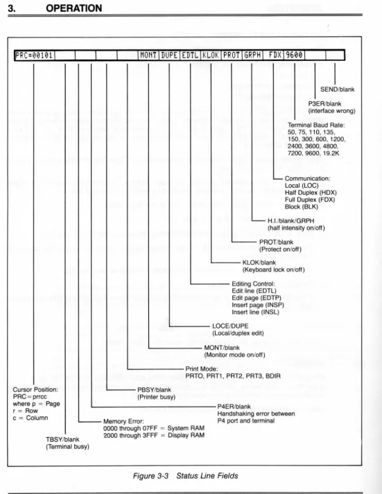
3.1 Introduction ... 3-1 3.2 Turning on the Terminal ... 3-1 3.3 Keyboard Controls ... 3-2 3.4 Setting Up the Terminal ... 3-8 3.5 Editing ... 3-8 3.6 Communicating with the Computer ... . . . .. . . ... . . .. . . ... . . .. 3-10 3.7 Editing ... 3-11 3.8 Printing. . . .. . . .. . . .. . . . .. . . .. . . .. 3-11
4. PROGRAMMING
4.1 Introduction ... 4-1 4.2 Monitor Mode ... 4-1 4.3 User and Status Lines ... 4-1 4.4 Line Lock ... 4-4 4.5 Disabling/Enabling the Keyboard ... 4-5 4.6 Cursor Display ... 4-6 4.7 Keyclick and Bell ... 4-6 4.8 Smooth Scroll ... 4-6 4.9 Video Display ... 4-6
Page
4.10 Visual Attributes ... 4-6
4.11 Special Graphics ... 4-9
4.12 Additional Screen Memory ... 4-9
4.13 Auto Page ... 4-10 4.14 Protect Mode ... . . .. . . .. . . .. . . ... . . .. . . .. . . .. . . .. . . .. 4-10
4.15 Normal and Reverse Linefeed . . . .. . . .. . . .. . . .. . . .. . . .. . . .. 4-12 4.16 Cursor Control Codes. . . .. . . ... . . .. . . .. . . .. 4-13
4.17 The Function Keys ... 4-14
4.18 The FUNCT Key ... 4-16
4.19 Addressing and Reading the Cursor Position... .. .. .. .. .. .. .. .... 4-16
4.20 Loading an Insert Character. . . .. . . .. . . .. . . ... . . .. . . .. 4-17
4.21 Tab Programming... . . . .. . . .. . . .. . . .. . . .. . . .. 4-18 4.22 Communication Modes... 4-19
4.23 Edit Keys ... " . . . .. 4-20
4.24 Editing Text ... 4-21
4.25 Clear Function ... " . . . .. . . .. 4-24
4.26 X-On/X-Off Control ... 4-25 4.27 Data Terminal Ready Control. . . .. . . .. . . . .. . . .. . . .. . . .. . . .. 4-25
4.28 User ROM' ... , . . . .. . . .. 4-25 4.29 Computer Port Programming ... , ... , ... , , . , ,. 4-25
4.30 Printer Port Programming ... , , .. , ... , ... , ,. . . .. 4-27 4.31 Send Function ... " ... 4-27
4.32 Print Function Programming ... , ... " , ... 4-30
5. PREVENTIVE MAINTENANCE AND CARE
5.1 Care ... , ... , .. , ... 5-1
5.2 Troubleshooting ... , .. , .. , ... 5-1 5.3 Repair ... " ... , ... , ... 5-5
5.4 Technical Assistance ... , ... , ... , ... 5-5
5.5 Reshipping the Terminal ... 5-6
Page
APPENDICES
A. Specifications . . . .. A-1 B. Statement of Limited Warranty.... . . .. . . .. . . .. . . .. . . .. B-1 C. ASCII Code Chart ... C-1
INDEX ... X-1 OPERATOR'S QUICK REFERENCE GUIDE ... X-3 SWITCH SETTING REFERENCE CHART... ... Inside back cover
Page
2-1 Location of Screws in Cabinet ... 2-1
2-2 Rear View of Terminal ... 2-3 2-3 Logic Board ... 2-5
2-4 Terminal Interior ... 2-6
2-5 A Typical S2 Switch Setting ... 2-10 2-6 Notches and Depressions in Chips ... 2-13 3-1 Rear Panel ... 3-1 3-2 Keyboard Layout ... 3-2
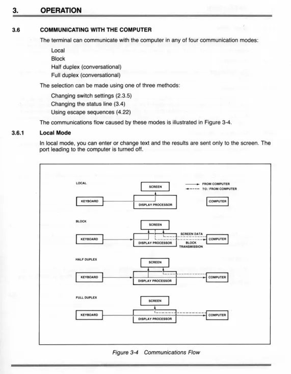
3-3 Status Line Fields ... 3-9 3-4 Communications Flow ... 3-10 4-1 Video Attributes and Monitor Mode ... .4-2 4-2 Special Graphics Characters ... .4-9 4-3 Print Modes ... 4-30 5-1 Normal Screen during Self Test 1 ... 5-4
Page
2-1 P3 Pin Connector Assignments
a. Computer Interface ... 2-4
b. Current Loop ... 2-4
2-2 Configuration of Computer Interface Connector for Current Loop ... 2-4
2-3 P4 (Serial Printer Interface) Pin Connector Assignments ... 2-7
2-4 External Switch Settings
a. S1 and S2 ... 2-8 b. Switch S1 Settings for Baud Rates ... 2-9
c. Switch S2 Settings for Parity ... 2-9
d. Switch S2 Settings for Communication Flow ... 2-10
2-5 Adding Screen Memory Chips to the Logic Board ... 2-12
3-1 Function of Keys ... ; .3-3
4-1 Monitor Mode Control Characters ... .4-3 4-2 Cursor Coordinates ... 4-4
4-3 Visual Attributes ... 4-7
4-4 Escape Sequences for Visual Attributes ... .4-8 4-5 Screen Attributes ... 4-9
4-6 Effects of Auto Page and Protect Mode on Linefeed Actions ... 4-12
4-7 Effects of Auto Page and Protect Mode on Reverse Linefeed Actions ... 4-13
4-8 Cursor Control Commands ... 4-13
4-9 Default Function Key Values ... 4-15
4-10 Tab Controls ... 4-18 4-11 Edit and Insert Modes ... 4-21
4-12 Editing Commands ... 4-22 4-13 Clear Commands ... 4-24 4-14 Baud Rate Values ... 4-26
4-15 Stop Bit Values ... 4-26
4-16 Parity Values ... 4-26 4-17 Word Length Values ... 4-26
4-18 Default Delimiter Values ... 4-28
4-19 Data Transmission Commands ... 4-28 4-20 Transmit Commands ... 4-30 4-21 Print Controls ... 4-31
5-1 Troubleshooting Terminal Problems ... 5-1
This manual explains how to install, operate, program, and troubleshoot the Model 950 ter-minal. The manual has been designed to help you use the terminal easily regardless of your previous experience with terminals.
1.1 TERMINAL OVERVIEW
The Model 950 is a compact state-of-the-art "smart" terminal that provides high level perfor-mance at low cost. Compatible with most computer systems, the Model 950 fits a wide variety of applications in the end-user environment.
The following features are standard: Monitor mode
Protected fields
Addressable/readable cursor Line and character insert/delete Local and duplex edit
Upper and lower case characters Tabbing
X-On/X-Off and Data Terminal Ready control Split screen with line lock
Programmable function keys (11 keys with 22 functions) 15 special graphics characters
On-screen status (25th) line Programmable user line Buffered auxiliary printer port Dedicated editing keys Smooth scrolling
Etched CRT face to reduce glare 14 x 10 character resolution
20 mA current loop communications Detached keyboard
Typewriter-styled keyboard with numeric keypad Self testing
1.1.1 Options
The terminal may be ordered with several options that enhance its already-comprehensive list of features. These options, available at additional cost, are:
• An additional 24 lines of memory, allowing total memory to be divided into either one 48-line page or two 24-48-line pages.
• An additional 48 lines of memory which can be added provided the optional 24 lines of memory (described above) have been installed. The total memory can be divided into one 96-line page, two 48-line pages, or four 24-line pages.
• An integral modem/dialer
1.2 HOW TO USE THIS MANUAL
1.2.1 Contents
The manual contains the following chapters:
2. INSTALLATION
How to install the terminal and make field modifications.
3. OPERATION
How to set up the terminal and use the basic operator controls.
4. PROGRAMMING
Describes the controls which enable you to include the terminal features in application programs.
5. TROUBLESHOOTING AND SERVICE
What to do if you have a problem with the terminal.
APPENDICES
Specifications, limited warranty, and ASCII code chart.
INDEX
OPERATOR'S QUICK REFERENCE GUIDE
Listing of all control and escape commands.
SWITCH SETTING SUMMARY
1.2.2 Symbols
Throughout the manual, special symbols are used to call your attention to information of special importance. The symbols used are as follows:
Information for every operator.
Warning concerning the safety of the operator or possible loss of data. When you see this note, STOP and read the note before proceeding!
1.2.3 Commands
Escape Sequences-Escape sequences are shown here with a space before alphanumeric character(s}. For example, the sequence shown as
ESC c
involves pressing only the ESCAPE key and a lower case character "c." This space is not to be entered as part of the sequence; it is included only for the sake of clarity.
The ESCAPE key is used in conjunction with one alphanumeric character and is always pressed and released before the second key is pressed.
Control Commands- The symbol used in this manual to represent the CONTROL (CTRL) key is /\.
The CONTROL (CTRL) key is always used simutaneously with the other character in the command; i.e., the CTRL key is pressed first and held down while the other key is pressed. (It is similar in action to the SHIFT key.)
Entering Commands- In order for commands to work as expected, the command must be entered exactly as shown. Notice whether the command requires upper or lower case, a number one or a lower case "L," a zero or an upper case "oh."
1.2.4 Terminology- The optional lines of memory allow you to create pages which are longer than the 24-line screen display. In the following chapters, the following terms will be used: Page
Screen or display
An amount of memory, defined by the memory chips installed. May be 24, 48, or 96 lines. The memory which constitutes one page may not all be visible at one time, since the screen displays only 24 lines at a time.
The 24-line terminal viewing area.
This manual is written for the latest Model 950 firmware. Earlier firmware (i.e., 1.0) functions may not correspond to this manual.
2.1 UNPACKING
To unpack the terminal, turn the opened packing carton on its side and slide the terminal out. It is not important to keep the terminal upright.
After you unpack the terminal, inspect it thoroughly for hidden damage and loose components or fittings, using the following checklist:
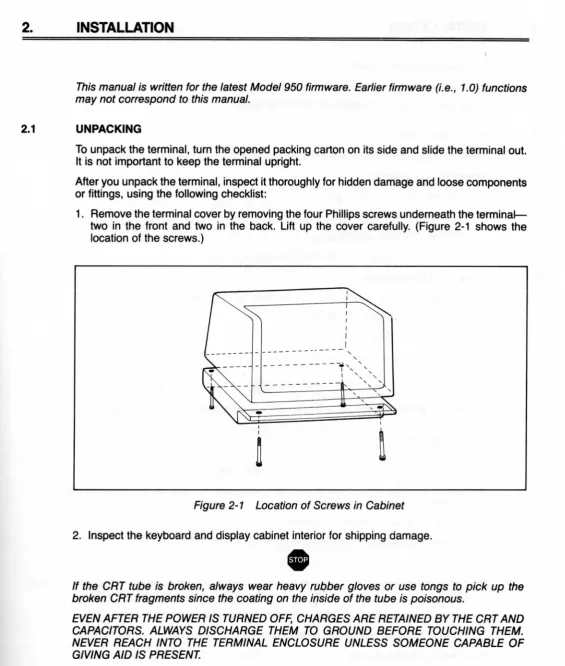
1. Remove the terminal cover by removing the four Phillips screws underneath the terminal-two in the front and terminal-two in the back. Lift up the cover carefully. (Figure 2-1 shows the location of the screws.)
--- , " - - - -- --- --r', "
I ',, ' , ,
,
I
~
Figure 2-1 Location of Screws in Cabinet
2. Inspect the keyboard and display cabinet interior for shipping damage .
•
If the CRT tube is broken, always wear heavy ruqber gloves or use tongs to pick up the broken CRT fragments since the coating on the inside of the tube is poisonous.
EVEN AFTER THE POWER IS TURNED OFF, CHARGES ARE RETAINED BY THE CRT AND CAPACITORS. ALWAYS DISCHARGE THEM TO GROUND BEFORE TOUCHING THEM. NEVER REACH INTO THE TERMINAL ENCLOSURE UNLESS SOMEONE CAPABLE OF GIVING AID IS PRESENT.
3. Examine cable harnesses for stress, loose or broken wires, or broken cable ties.
4. Examine all internally-mounted components for loose or missing hardware.
5. Tighten any loose hardware.
6. Clean any loose debris from the cabinet interior.
7. Replace the cover. Do not overtighten the screws.
2.2 PREPARING THE SITE
Make sure you are ready with the proper power and a sufficiently-large table.
2.2.1 Power Requirements
115 VAC 60 Hertz at 0.5 amp
OR
230 VAC 50 Hertz at 0.25 amp
NEMA standard 5-15R, 3-prong receptacle (US only)
2.2.2 Physical Requirements
You will need a sturdy, level surface for the terminal. The dimensions are:
Cabinet 16.50 inches (41.9 cm) wide
14.00 inches (35.6 cm) high
14.25 inches (36.2 cm) deep
In addition, allow 4 inches (10.2 cm) above and behind the terminal for ventilation.
2.3 INSTALLATION
PROTECT YOURSELF!
As you install the terminal, observe standard safety precautions (as you would any electrical or electronic equipment).
The actual installation consists of only five steps:
1. Connect the keyboard to the terminal (2.3.1).
2. Configure the terminal for either 115 or 230 VAC operation (2.3.2).
3. Connect the terminal to the computer or a modem (and to a printer, if used) (2.3.3 and
2.3.4)
4. Configure the terminal by setting exterior switches (2.3.5). 5. Plug the terminal into the wall outlet (2.3.6).
2.3.1 Connecting the Keyboard
Connect the end of the keyboard cable to the connector labeled P6 on the rear of the terminal
(Fig. 2-2).
/ / / /111111111 1 1 1 1 1 1 \ \ \\ \\\
AIR VENTS
<0
··
iJ
··
"CD"CONTRAST ADJUSTMENT
I
FU::L~=-'-I...J
SERIAL NUMBER I SW
I
POWER CORD ON/OFF POWERFigure 2-2 Rear View of Terminal
2.3.2 Power Configuration
Check the power select switch on the rear of the terminal. If necessary, change it to match your power requirements (either 115 or 230 V) and reinstall the switch blocking strip. You will set Hertz to match your power frequency when you set Switch S2, dipswitch 9.
2.3.3 Connecting the Terminal to a Computer System or Modem
You can connect the terminal directly to your computer system or indirectly with a modem using the pin connector labeled P3.
You can use either RS232C or current loop. An RS232C interface limits the maximum distance between the terminal and computer or modem to 50 feet (if shielded, twisted-pair cable is used). A current loop interface allows the terminal to be located up to 1,000 feet from the computer.
For an RS232C installation, use a shielded, twisted-pair cable with a connector which has been configured to match the pin connector assignments listed in Table 2-1 a.
Table 2-1 b lists the pin assignments of the P3 connector for current loop. For a current loop installation, configure the cable connector as described in Table 2-2. The current loop config-uration can be anyone of the following:
1. Full duplex, active transmit. active receive 2. Full duplex, active transmit. oassive receive
3. Full duplex, passive transmit, active receive 4. Full duplex, passive transmit, passive receive
5. Half duplex, either active or passive transmit/receive
Table 2-1 P3 Pin Connector Assignments a. Computer Interface
(Reference EIA Standard RS232C for Signal Definitions)
Pin No.
1 2 3 4 5 6 7
8
Signal Name
Frame Ground Transmit Data Output Receive Data Input Request to Send Output Clear to Send Input Data Set Ready Input Signal Ground Carrier Detect Input
20 Data Terminal Ready Output
b. Current Loop
Pin No. Signal Name
9 20 mA source ( + 12V. no load)
10 Detected current loop data
12 Current Loop +. Receive
13 Current Loop -. Transmit
14 20 mA source ( + 12V. no load)
24 Current Loop -. Receive
25 Current Loop +. Transmit
Table 2-2 Configuration of Computer Interface Connector for Current Loop
Transmission
1. Full duplex transmit
2. Full duplex receive
3. Half duplex
Current Source·
Active
Passive
Active
Passive
Active
Passive
2-4
Cable Connector
Jumpers
9 to 25
14 to 12
3 to 10
3 to 10
3 to 10
9 to 25 12 to 13
3 to 10 12 to 13
Pin Connection
7
-13+ 13-25+
7
-24+
12+ 24
-
7-24+
I\)
tn
P2 MONITOR CONNECTOR
P2-PIN 6
S2
1ST PAGE RAM 6116
SYSTEM ROMS
Figure 2-3 Logic Board
6545 CRT CONTROLLER
6522 ACIA
6502 CPU
USER
• ROM
SLOT
POWER , . SUPPLY CONNECTOR
z
en
~
r-~
o
ANODE (HIGH VOLTAGE)
+12 V REGULATOR
+ 5 V REGULATOR
52
51
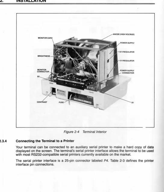
Figure 2-4 Terminal Interior
2.3.4 Connecting the Terminal to a Printer
Your terminal can be connected to an auxiliary serial printer to make a hard copy of data
displayed on the screen. The terminal's serial printer interface allows the terminal to be used
with most RS232-compatible serial printers currently available on the market.
The serial printer interface is a 2S-pin connector labeled P4. Table 2-3 defines the printer
interface pin connections.
Table 2-3 P4 (Serial Printer Interface) Pin Connector Assignments (Reference EIA Standard RS232C for Signal Definitions)
Pin No.
1 2 3 4 5 6 7 8 20
Signal Name
Protect Ground
Receive Data (input) Transmit Data (output) Request to Send (input)
Clear to Send (output)
Data Set Ready (output) Signal Ground
Data Carrier Detect (output) Data Terminal Ready (input)
2.3.5 Configuring the Terminal for the Computer and Printer
Two switches (located on the rear of the terminal as shown in Fig. 2-2) allow you to configure
the terminal to operate according to the requirements of your computer system and printer and change the operation of the terminal.
The switch able features are:
Baud Rates-You can select any of 15 baud rates according to the requirements of your computer system and printer.
Hertz-You can set the Hertz switch to match your powerline frequency.
Parity, Stop Bits, and Word Structure-You can set the parity, number of stop bits, and number of bits in the word structure to match the requirements of your computer system.
Communications-You can select half or full duplex (conversational mode), local, or block
mode.
Video Display-You can cause the display to be green on black or black on green.
Keyclick-You can select keyclick or silent key action.
These parameters can also be changed by codes entered from the keyboard or sent from
the computer.
Switch Settings-Two external switches (S1 and S2) on the rear of the terminal can be set to control many of the possible parameters described above. The possible switch settings are listed in Tables 2-4a through 2-4d. Figure 2-5 shows a typical switch setting.
Table 2-4 External Switch Settings
a. S1 and S2
Position
Open Closed
Switch Dipswitch (Up) (Down) Function
S1 1,2,3,4 Computer baud rate;
see Table 2-4b
5 x Seven-bit word structure
x Eight-bit word structure
6 x Two stop bits
x One stop bit
7,8,9,10 Printer baud rate; see Table 2-4b
S2 x Duplex edit
x Local edit
2 x Blinking cursor
x Steady cursor 3,4,5 Parity; see Table 2-4c
6 x Green on black display
x Black on green display
7,8 Communication mode;
see Table 2-4d
9 x 60 Hertz'
x 50 Hertz'
10 x Keyclick off
x Keyclick on
Note
1. Set to match powerline frequency to avoid screen flicker.
Terminal Printer
Legend
D = Down/closed/O U = Up/open/1
3
X
D
D
U
U
Legend
X = Either up or down D = Down/closed/O U = Up/open/1
Table 2-4b Switch S1 Settings for Baud Rates
Dipswitches
2 3 4
7 8 9 10 Baud Rates
D D D D 9600
U D D D 50
D U D D 75
U U D D 110
D D U D 135
U D U D 150
D U U D 300
U U U D 600
D D D U 1200
U D D U 1800
D U D U 2400
U U D U 3600
D D U U 4800
U D U U 7200
D U U U 9600
U U U U 19200
Table 2-4c Switch S2 Settings for Parity
Oipswitch 4
X
D
U
D
U
5
D
U
U
U
U
Parity Setting
No parity
Odd parity (receive/transmit)
Even parity (receive/transmit) Mark (transmit parity disabled) Space (transmit parity disabled)
If word structure, parity, or stop bits are set incorrectly, the terminal will only display "@" signs when data is received (if any data is received).
Table 2-4d Switch S2 Settings for Communication Mode
Dipswitch
7
0
0
U
U
8 Communication
0 Half duplex
U Full duplex
0 Block
U Local
~hHf#1
II
L' _
KEYCLICKON(DOWN) . L . _ _ _ _ 60 HERTZ (UP)
-HALF DUPLEX (DOWN)
. HALF DUPLEX (DOWN) L - -_ _ _ _ _ _ _ _ GREEN ON BLACK (UP)
L -_ _ _ _ _ _ _ _ __ ODD PARITY (UP)
L -_ _ _ _ _ _ _ _ _ _ ODD PARITY (DOWN) ' - - - -ODD PARITY (DOWN) ' - - - -BLiNKINGCURSOR(UP) L - -_ _ _ _ _ _ _ _ __ _ _ _ _ DUPLEX EDIT(UP)
Figure 2-5 A Typical S2 Switch Setting
Whenever you change any switches, turn the terminal power off and back on. This allows the software to scan all new switch positions.
Set the dipswitches prior to turning on power to the terminal and record the switch settings on the form in 5.4.1.
2.3.6 Plugging the Terminal In
After all cables have been connected and switches set, plug the terminal into the wall outlet.
2.4 INSTALLATION CHECKLIST
Before you turn on the terminal, answer the following questions: 1. Does your power plug match the wall socket?
2. Did you set the power selector switch to match your power requirements?
3. Is the interface cable to the computer system properly wired and attached to both the terminal and the computer?
4. If you are using a printer, did you plug in the printer interface connector? 5. Did you set the switches for the correct
Baud rate (both for terminal and printer)? Stop bits?
Word structure? Parity?
6. Did you set switches for the desired communication mode? 7. Did you plug the terminal into the wall outlet?
8. Did you plug the keyboard into the terminal?
2.5 FIELD MODIFICATIONS
2.5.1 Composite Video Option
If you wish to drive a monitor in addition to or other than the terminal monitor, modify the logic board (Fig. 2-3). Add an Amphenol BNC connector (Part 227169-5) to the rear of the terminal case. (See Fig. 2-4 for recommended placement of the connector.)
Connect the center lead of the BNC connector to P2 pin 6 and the BNC ground lead to P2 pin 3. Cut the trace between E1 and E2. Install a jumper between E3 and E4.
The monitor should not be more than 10 feet from the terminal.
2.5.2 Additional Pages of Screen Memory
The terminal can be modified to provide additional pages of screen memory. If you ordered the terminal with this additional memory, this modification will have been made at the factory before the terminal was shipped. You can perform this modification in the field later by following these directions.
To add 24 lines (one page) of screen memory to the terminal, you will need to add one Chip. This will provide a total of 48 lines of memory. You can increase this total to 96 lines by adding two more chips to the second chip. (You can not add only two chips; you must add a total of either one or three chips.)
You will need 2 K by 8 bit static RAM chips with a maximum rise time of 150 nanoseconds. (These may be purchased from your dealer or distributor.) Approved manufacturers include
the following:
Brand
Hitachi Toshiba Mostek
Part No.
HN 6116-150nt TMM 2016-150ns MK 4802N-150ns
To install the chip(s), follow these steps:
1. Remove the terminal cover by removing the four Phillips screws underneath the terminal-two in the front and terminal-two in the back. Lift up the cover carefully. (Figure 2-1 shows the location of the screws.)
•
Even after the power is turned off, charges are retained by the CRT and capacitors.
Always discharge them to ground before touching them. Never reach into the terminal
enclosure unless someone capable of giving aid is present.
2. Add chip(s) to the logic board as described in Table 2-5.
Install the chips carefully to avoid bending the pins. Each chip has a half-moon notch on the
side or a depression on the top. This notch or depression must be oriented to match the
orientation of the other chips on the logic board (Fig. 2-6).
3. Replace the cover, being careful not to overtighten the screws.
Note
Table 2-5 Adding Screen Memory Chips to the Logic Board
Lines of Memory Being Added
24
48*
No. of Chips Added
One
Two
Location on Logic Board of New Chips
Position A34
Positions A35 and A36
*You must add a chip into Position A34 before you add chips into Positions A35 and A36.
a. Notch in Chip b. Depression in Chip
Figure 2-6 Notches and Depressions in Chips
This manual is written for the latest Model 9S0 firmware. Earlier firmware (i.e., 1.0) functio