PIN: 800-0345
SUN-l SYSTEM REFERENCE MANUAL Draft Version 1.0
July 27, 1 982
The Sun-1 Workstation (TI1 Sun Microsystems Inc.) is a personal computer system combining high resolution graphics with Powerful local processing and optional high speed net-working. This document is intended to provide all information needed to install, operate, and program the Sun-1 . Workstation.
This version ('ornpletely supersedes all previous drafts. Your questions, corrections, and criticisms are welcomed. Please respond to Martin Rattner or Henry McGilton at Sun Microsystems, Inc.
Portions or this document are based upon material origi-nally written at Stanford University by William Nowicki, Jef-frey '~ogul, Tim l-mnn, VaughaI~ Pratt, and David Brown, whose contric· tions are gratefully acknowledged. Used with permis-sion.
Copyright 1982 Sun Microsystems, Inc.
2310 Walsh Avenue Santa Clara, CA 95051
SUN-1 SYSTEM REFERENCE MANUAL
CONTENTS
CONTENTS. • • • • • • • • • • • • • • • • • • • • •.• • • • • • • • • • • • • • • • • • • • • • • • • • • • • • • • • • • • • • i
LIST OF FIGURES ••••••••••••••••••••••••••••••••••••••••••••••••••••• iv
LIST OF T .ABLES •••••••••••••••••••••••••••••••••• " • • • • • • • • • • • • • • • • • • • i v
1.
2.
3.
~.
INTRODUCTION •••••••••••••••••••••••••••••••••••••••••••••••••• eo. 1 1 1 2 1 .1 1 .2 1.3 Description •••••••••••••••••••••••••••••••••••••••••••••••• Physical Packaging ••••••••••••••••••••••••••••••••••••••• Notations Used in this Document •••••••
...
HARDWARE DESCRIPTION AND CONFIGURATION •••••••••••••••••••••••••• 3
3 4 2.1 Multibus Interface ••••••••••••••••••••••••••••••••••••••••• 2.2 Processor Board ••••••••••••••••••••••••••••••••••••••••••••
2.3 2.4 2.5
2.6
2.7 2.8 2.9 2.10 2.11 2.2.1 2.2.2 2.2.3U ARTs •••••••••••••••••••••••••••••••••••••••••••••••
Timers •••••••••••••••••••••••••••••••••••••••••••••• Multibus Priority ••••••••••••••••••••••••••••••••••• Graphics Board ••••••••••••••••••••••••••••••••••••••••••••• Memory Expansion ••••••••••••••••••••••••••••••••••••••••••• Video Display ••••••••••••••••••••••••••••••••••••••••••••••
Keyboard •••••••• , •••••••••••••••••••••••••••••••••••••••••••
Ethernet Board ••••••••••••••••••••••••••••••••••••••••••••• Disk Controller •••••••••••••••••••••••••••••••••••••••••••• Multibus Memory ••••••••••••••••••••••••••••••••••••••••••••
Lark Disk Subsystem •••••••••••••••••••••••••••••••••••••••• Fujitsu Disk Subsystem ••••••••••••••••••••••••••••••••••••• INST .ALLATION ••••••••••••••••••••••••••••••••••••••••••• " ••••••••
3.1 3.2
3.3
3.4
3.5 3.63.7
Unpacking Instructions ••••••••••••••••••••••••••••••••••••• Safety Precautions ••••••••••••••••••••••••••••••••••••••••• Card Cage Configuration ••••••••••••••••••••••••.•••••••••••• Removal and Installation of Circuit Cards •••••••••••••••••• Internal Cabling ••••••••••••••••••••••••••••••••••••••••••• Set-up ••••••••••••••••••••••••••••••••••••••••••••••••••••• 3.6.1 Keyboard ••••••••••••••••••••••••••••••• ~ •••••••••••• 3.6.2 R5-232 Serial Ports •••••••••••••••••••••••••••••••••
3.6.3
Disk Subsystem ••••••••••••••••••••••••••••••••••••••3.6.4 3
Mbit/sec Ethernet Board ••••••••••••••••••••••••••• 3.6.5 Mouse ••••••••••••••••••••••••••••••••••••••••••••••• UNIX ••••••••••••••••••••••••••••••••••••••••••••••••••••••• 5 5 6 6 7 8 8 10 10 12 13 13 14 14 1~ 14 15 16 17 17 18 18 20 20 20 USING THE SUN PROCESSOR ••••••••••••••••••••••••••••••••••••••••• 21Getting Started •••••••••••••••••••••••••••••••••••••••••••• 21
UNIX ••••••••••••••••••••••••••••••••••••••••••••••••••••••• 21 The ROM Moni tor •••••••••••••••
0...
22 ~.3.1 What 1s the monitor? ••••••••••••••••••••••••••••••• 22~.3.2 Absolute Rules ••••••••••••••••••••••••••••••••••••••
23
The ROM Monitor Commands ••••••••••••••••••••••••••••••••••• 23
1& .1
4.2
4.3
4.4
SUN-1 SYSTEM REFERENCE MANUAL Page ii
5. 4.5
~.6
Loading Programs •••••••••••••••••••••••••••••••••••••••••••
4.5.1
8-record Format ••••••••••••••••••••••••••••••••••••• 4.5.2 Example of Down-line Loading •••••••••••••••••••••••• Traps ••••••••••••••••••••••••••••••••••••••••••••••••••••••4.6.1
Bus/Address Error Traps ••••••••••••••••••••••••••• ~.4.6.2 Watchdog Timer •••••••••••••••••••••••••••••••••••••• Tracing programs •••••••••••••••••••••••••••••••••••••••••••
4.7.1
Breakpoint traps •••••••••••••••••••••••••••••••••••• 4.7.2 Trace traps ••••••••••••••••••••••••••••••••••••••••• PROGRAMMING THE SUN PROCESSOR ••••••••••••••••••••••••••••••••••• 5.1 Processor ••••••••••••••••••••••••••••••••••••••••••••••••.••5.2
5.3
5.4 5.5
5.6
5.1 .1
5.1.2 5.1.3
5.1.4
Memory 5.2.1 5.2.2 5.2.3 5.2.4 5.2.5 5.2.6Physical Address Space •••••••••••••••••••••••••••••• Exception Handling •••••••••••••••••••••••••••••••••• Interrupts •••••••••••••••••••••••••••••••••••••••••• Initialization •••••••••••••••••••••••••••••••••••••• Management •••••••••••••••••••••••••••••••••••••••••• Overview •••••••••••••••••••••••••••••••••••••••••••• Context Register •••••••••••••••••••••••••••••••••••• Segment Map ••••••••••••••••••••••••••••••••••••••••• Protection ••••••••••••••••••••••••••••••••••••••••••
Page Map ••••••••••••••••••••••••••••••••••••••••••••
Page Control •••••••••••••• & • • • • • • • • • • • • • • • • • • • • • • • • • ROM Vector Table •••••••••••••
...
5.3.1 5.3.2 5.3.3 5.3.4 5.3.5 5.3.6 5.3.7 5.3.8VT entries used by the hardware ••••••••••••••••••••• Information VT entries •••••••••••••••••••••••••••••• Single-character I/O •••••••••••••••••••••••••••••• Sun keyboard input (scanned by monitor
refresh routine} ••••••••••••••••••••••••••
Frame buffer output and terminal emulation •••••••••• Mouse support ••••••••••••••••••••••••••••••••••••••• Operating System support •••••••••••••••••••••••••••• Interfaces between PROMs •••••••••••••••••••••••••••• The Sun Keyboard •••••••••••••••••••••• ~ ••••••••• ~ •••••••••• The Sun Graphics System •••••••••••••••••••••••••••••••••••• 5.5.1 5.5.2 5.5.3 5.5.4 5.5.5 5.5.6
The Frame Buffer •••••••••••••••••••••••••••••••••••• RasterOps ••••••••••••••••••••••••••••••••••••••••••• Frame Buffer Addressing •••••••••
Registers and Function Unit ••••• 5.5.4.1 Destination Register .•• 5.5.11.2 5.5.11.3 5.5.11.4 5.5.4.5 5.5.4.6 5.5.4.7
Source Register ••••••••••••••••••••••••• Mask Register •••••••••••••••••••••••••••••• Function Register •••••••••••••••••••••••••• Width Register ••••••••••••••••••••••••••••• Control Register ••••••••••••••••••••••••••• X-Y Registers •••••••••••••••••••••••••••••• Graphics Board Multibus Interface ••••••••••••••••••• Graphics Board Address Decoding ••••••••••••••••••••• Terminal Emulation •••••••••••••••••••••••••••••••••••••••••
5.6.1
5.6.2
ANSI Terminal Emulation ••••••••••••••••••••••••••••• 5.6.1.1 ANSI Control Sequence Syntax ••••••••••••••• 5.6.1.2 ANSI Control Functions ••••••••••••••••••••• Vector-Drawing Control Functions •••••••••••••••••••• 5.6.2.1 Graph and Point Mode Address Format ••••••••
27 27 28 29 30 32 32 32 33 3~ 34 34 35 36 36 37 31 37 39 40 40 41
41
42 42 42 43 4546
46 liB 48 51 51 51 53 54 55 55 55 55 55 55 56 56 57 59 59 59 60 65 65SUN-1 SYSTEM REFERENCE MANUAL Page iii
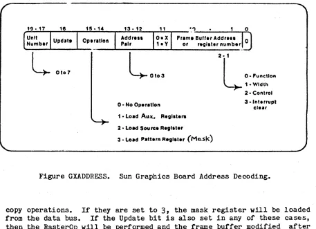
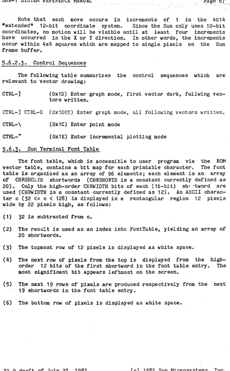
5.6.2.2 Incremental plotting mode •••••••••••••••••• 66 5.6.2.3 Control Sequences •••••••••••••••••••••••••• 67 5.6.3 Sun Terminal Font Table ••••••••••••••••••••••••••••• 67
6. DIAGNOSTICS ..••••••••••••••••••.•••••••••••••••••••••••••••••••. 68 6.1 Factory Test Procedures •••••••••••••••••••••••••••••••••••• 68 6.2 Power-On Diagnostics ••••••••••••••••••••••••••••••••••••••• 68 6.3 Diagnostic PROMs ••••••••••••••••••••••••••••••••••••••••••• 68 6.4 Installation of Diagnostic PROMs ••••••••••••••••••••••••••• 70 6.5 Decoding 64K RAM Error Information ••••••••••••••••••••••••• 70
6.5.1
Decoding On-Board RAM Locations •••••••••••••••••••••71
6.5.2 Decoding Chryslin 128K RAM Locations ••••••••••••••••
71
6.5.3
Decoding Chryslin 512K RAM Locations •••••••••••••••• 72 Appendix A.Appendix B. Appendix C. Appendix D.
Frame Buffer Programming Example ••••••••••••••••••••••• 73 C Language constants for the Sun Graphics Board •••••••• 75 ROM Vector Table header file •••••••••••••••••••••••••••
77
Sun Keyboard Translation Table Definitions ••••••••••••• 79
SUN-1 SYSTEM REFERENCE MANUAL Page iv
LIST OF FIGURES
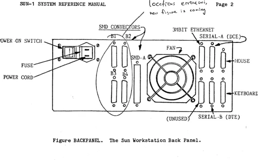
BACKPANEL. The Sun Workstation Back Panel... 2
GRAPHICS. Organization of the Sun Graphics Board...
7
GBOARD. Setting Multibus base address on Sun Graphics Board... 8
KEYS. Keyboard Layouts... 9
ETHERNET. Sun 3 MEit/sec Ethernet installation... 11
MEMV~N. Memory Mapping on the Sun Processor •••••••••••••••••••••••• 38 M}~~~R. Addressing Scheme for Segment and Page P~p Entries •.••••••• 39 KEYBOARD. The Sun Keyboard •••••••••••••••••••••••••••••••••••.••••• 49 SCREEN. The Sun Graphics Screen... 52
RASTEROP. The "RasterOp" Concept ••••••••••••••••••••••••••••••••••• 52 RASTEREXAMPLE. A Boolean function ••••••••••••••••••••••••••••••••••
53
GRAPHBLOCK. Sun Graphics Board Block Diagram ••••••••••••••••••••••• 54 GXADDRESS. Sun Graphics Board Address Decoding... 58LIST OF TABLES Wiring of UARTs... 5
Usage of timers... 5 Card cage configuration ••••••••••••••••••••••••••••••••••••••••••••• 14 S-record format ••••••••••••••••••••••••••••••••••••••••••••••••••••• 27
Monitor exception messages •••••••••••••••••••••••••••••••••••••••••• 29 Information saved on bus errors ••••••••••••••••••••••••••••••••••••• 31 Processor logical address space ••••••••••••••••••••••••••••••••••••• 34
Segment map protection codes •••••••••••••••••••••••••••••••••••••••• 40 Page map address space codes •••••••••••••••••••••••••••••••••••••••• 41 Sun keyboard control characters ••••••••••••••••••••••••••••••••••••• 50
SUN-1 SYSTEM REFERENCE MANUAL Draft Version 1.0
1 • INTRODUCTION 1.1. Description
The Sun-1 Workstation (T~': Sun Microsystems, Inc.) is a personal computer system that combines high resolution graphics with powerful local processing and optional high speed networking. The workstation is based on the Motorola 68000 processor. It has a 1024 by 800 pixel bit-map display, a fully up/down encoded keyooard,.?56K bytes of on-board RAM memory with memory management, and a "RasterOp" mechanism for high-speed display updates.
The Sun-1 Workstation electronics consists of two PC boards: a pro-cessor board and a frame buffer (graphics) board. The workstation uses the Intel Multibus., which is proposed IEEE standard 796, so many other common peripheral interfaces are commercially available.
Several optional interfaces are available for the Sun-1. An Ether~
net interface card allows the Sun Wor~~station to connect to a 3Mb Ether-net local Ether-network. A disk interface allows up to four SMD disk drives to be connected, such as the Fujitsu M2313K or the CDC Lark... A mouse pointing device may be connected to the existing parallel input port. 1.2. Physical Packaging
The Sun-1 Workstation consists of two physical units, a display module and a detached keyboard. The display module contains the video mOnitor, card cage, power supply, cooling fan, and back panel. The card cage has seven Multibus slots ••• , two of which are occupied by the pro-cessor board and the graphics board.
The back panel is illustrated in Figure BACKPANEL. The five con-nectors labelled "SMD" are used to connect to up to four SMD disk drives using the optional disk controller. Only the Sun keyboard should be plugged into the connector labelled "Keyboard". A mouse may be plugged into the "mouse" connector. The R5-232 serial ports labelled "An and "B" are used to connect equipment such as terminals, modems, printers, • Mult1bus is a trademark of Intel Corporation •
•• Lark is a trademark of Control Data Corporation.
••• A small number of the earliest-manufactured units have six-slot card cages.
SUN-1 SYSTEM REFERENCE MANUAL Page 2
3HBIT ETHERNET SERIAL-A POWER- -ON S\.JITCH
FAN,.
FUSE
o 0
POWER CORD o 0
~~
o 0Figure BACKPANEL. The Sun Workstation Back Panel.
etc. See the chapter on "Installation" below for information about con-necting peripheral equipment to the Sun Workstation.
Be sure to keep the area behind the fan unobstructed. 1.3. Notations Used in this Document
i-lOUSE
KEYBOARD
Integers are normally written in decimal; if preceded by "Ox" they~ are hexadecimal.
Software interfaces and programming examples are specified in the C programming language-.
SUN-1 SYSTEM REFERENCE MANUAL Page 3
2. HARDWARE DESCRIPTION AND CONFIGURATION 2.1. Multibus Interface
The Sun-1 Workstation uses two busses: a synchronous, high-speed memory bus for processor-memory communication and the the IEEE 796 Bus (Intel l-Iul tibus) for input/output and peripherals. The IEEE 796 Dus is an asynchronous bus, accomodating devices with various transfer rates while maintaining maximum throughput. The Multibus provides 8-bit and 16-bit data transfers and 20-bit addressing, extendable to 24-bit addressing. It allows multiple masters to share the same bus, and pro-vides serial (daisy-chain) as well as parallel priority resolution schemes. The Multibus has a secondary backplane connector, the P2 con-nector, for int€e:-module connections. This connector is used in the Sun workstation for the high-speed memory bus mentioned above.
In order to offer a consistent model for 68000 programmers, the Sun processor board generates 68000 byte order on the Multibus. This means that the low-order or the even byte is placed into bits D8 through D15, whereas the high-order or odd byte is placed into bits DO through D7. If the processor board communicates with a byte-organized Multibus dev-ice, it is typically necessary to reverse the byte-order in software.
The Sun 68000 board generates the 20 address lines on the standard IEEE 796 Bus. Using these 20 address lines, the board can address up to one megabyte of memory and one megabyte of input/output locations.
The Sun processor board contains an on-board precision voltage reference for power-on reset. Multibus INIT is generated whenever the voltage falls below
4.5
Volt. In addition, Multibus INIT can be gen-erated by executing the 68000 RESET instruction. Note that in this standard configuration the 68000 always drives INIT to the Multibus and the 68000 cannot be re~et by an INIT from the Multibus.If the 68000 accesses the Multibus and does not receive transfer acknowledge within 1 to 3 milliseconds, the access aborted via bus error. The timeout period in the Sun processor includes the" Multibus acquisition time. Thus, if a peripheral locks up the bus for more than 1 millisecond, timeout can occur.
See also the section titled "Multlbus Priority" below.
a data will be board device
For more information about the Multibus, consult the following references:
R. W.
Boberg,"796
Microprocessor Bus Standard", Computer, October, 1980.This publication in the IEEE Computer Magazine gives a good introduction and overview of the bus.
SUN-1 SYSTEM REFERENCE MANUAL Page 4
IEEE, nProposed 796-Microprocessor Bus Standard n, with Errata, December, 1981.
This is the official copy of the Standard and includes up-to-date revisions and errata. It is available from:
MicroBar, Inc. Attn: Rich Boberg 1120 San Antonio Rd. Palo Alto, CA 94303 415-964-2862
Intel Corp., nIntel Multibus Specificationn, Revised April 1981. This is the Intel version of the Standard, recommended in ad-dition to the IEEE version. This document is a superset of
the IEEE standard and contains some application-specific in-formation. It Is available as Manua~ Number 9800683-03 from:
Literature Department Intel Corporation 3065 Bowers Avenue Sant~ Clara, CA 95051 408-987-8080
or from local Intel sales offices.
Sun Microsystems, Inc., Sun 796-Bus Interface ~~nua1, forthcoming. This document will describe design considerations which apply. when interfacing other Multibus boards to the Sun Workstation boards.
2.2. Processor Board
The Sun processor board contains a Motorola 68000 processor running with a 10 ~lliz clock, 256 Kbytes of RAM memory with byte parity, an Intel 827~ dual UART (equivalent to NEC7201), an Am9513 System Timing Con-troller, and a 16 bit parallel input port. For programming information on the UART and timer chips, see the manufacturers' data sheets-.
The next chapter on nInsta1lation" provides instructions for installing or removing boards in the Sun-1 card cage.
- Component Data Catalog. Intel Corporation, Santa Clara, CA.; Am9500 Family Interface Manual, Advanced Micro Devices, Inc., Sunnyvale, CA.
SUN-1 SYSTEM REFERENCE MANUAL
2.2.1. UARTs
The Intel
8274
orNEe 7201
dual UARTs are wired as follows: UARTA
is wired ason UART Outputs: TXDA
RTSA Inputs: RXDA
CISA DCDA
a DCE port. on Connector
RXDA CTSA TXDA HTSA DTRA Baud rate: generated by Timer 4.
UART B is wired as a DTE port.
Output: TXDB TXDB
I npu t : RXDB RXDB
Baud rate: generated by Timer
5.
2.2.2. Timers
Page 5
The AMD 9513 timer chip is configured with an input frequency of 5 MHz and FOUT of 2.5 MHz (connected to Gate 1). It contains five timers, whose usage is described in the following table:
Timer Usage
1 Watchdog. OUT generates BERR/Reset. [1] 2 User timer.
3
4
5
OUT causes INT6. Refresh timer. OUT causes INT7.
UART
A.
OUT con-nected to UART A TX/RX elk.UART B. OUT
con-nected to UART B TX/RX Clk.
Operating Mode Out=TC, Repetitive
Out=toggle,
re-petitive (one shot). Reset by refresh routine. Out= toggl e, repeti tive. Out=toggle, repeti tive. Normal Frequency interval= 2.8 msec
[2]
interval= 2 msec
[2]
16 times UART baud rate
16 times UART baud rate
Notes: [1] Causes reset if Refresh Timer Out
(13)
is Low.[2] Difference between timers 1 and 3 determines Multibus timeout period.
SUN-1 SYSTEM REFERENCE MANUAL
2.2.3. Multibus Priority
The Sun-1 processor board is always configured to be priority Multibus master, by grounding (asserting) (BPRN) on the processor board.
Page 6
the highest-Bus Priority In
I f the 68000 board is used in conjuntion with a Multibus DMA board, such as a disk controller, that does not support Common Bus Request (CBRQ) then the 68000 board must be configured such that it gives up the Multibus after every Multibus cycle. This also will cause three
addi-tional wait states for each Multibus access. The Interphase 2180 disk controller is an example of a Multibus DMA board requiring this confi-guration.
On the other hand, if all Multibus DMA devices (Bus Masters) ~ support CBRQ, then the CBRQ jumper on the processor board is not required. Instead, the 68000 board will retain bus mastership until a lower priority "master requests it by asserting CBRQ. Following a CBRQ, the current Bus Master has to yield mastership for at least one cycle.
The CBRQ jumper is the leftmost pair of pins at location J902 on the processor board, viewing the board with the Multibus at the bottom. 2.3. Graphics Board
The Sun graphi~ ~ system is a high-resolution bit-mapped frame buffer and display processor on one Multibus board. The general organi-zation of the graphics board is illustrated in Figure GRAPHICS. There is a small amount of hardware assistance to perform a set of simple high bandwidth operations called "RasterOps". This results in a Simple yet flexible graphics deVice, with the performance needed to support sophis-ticated user interfaces. The section below entitled nT-he Sun Graphics~ System" contains detailed speCifications of the programming interface to the Graphics board.
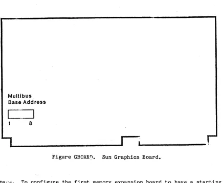
The graphics board has only one switch, which is illustrated in Figure GBOARD. This switch is used to set the Multibus base address (in Multibus Memory Space). It may be set to any address multiple of Ox20000 between OxO and OxEOOOO.
The standard address for the graphics board is OxCOOOO. Any addi-tional graphics boards are placed at successively lower addresses.
SUN-1 SYSTEM REFERENCE MANUAL
• Bit-Manipu1ation
• XIV Addressing Hardware
• Graphical Object Cache • Next Address Generation
• Graphical Object Selection Software • Function Selection
Host ... RasterOP
..
Frame ... Video,
,.
,Processor Hardware Buffer Monitor
AasterOP unit performs read-modify-write cycle Destination in frame buffer
Source operands can come from frame buffer or host computer
address OxOOOOO Ox20000 Ox40000 Ox60000 Ox80000 OxAOOOO OxCOOOO OxEOOOO
Figure GRAPHICS. The Sun Graphics Board.
DIP switch 8
7
6
5
4 3
2
1
(standard setting)
2.4. Memory Expansion
Page 1
The Sun memory expansion board provides 768K bytes of additional "on-board" memory for the Sun processor. It is connected to the proces-sor board via the Mult1bus P2 connector and permits access by the 10MHz
68000 without wait states. Up to two of these board can be added to the Sun-1 workstation.
The memory expansion board has only one option: to be located starting at 256K or starting at 1M within the on-board memory address
SUN-1 SYSTEM REFERENCE MANUAL
Multibus Base Address
C~
1 8
I
Figure GBOAR~. Sun Graphics Board.
Page 8
spac~. To configure the first memory expansion board to have a starting address of 256K, insert the 7~S138 chip at location U1006. To configure the second board for a starting address of 1M, insert the 7~S138 chip at location Ul008. See the next chapter for installation instructions. 2.5. Video Display
The video display monitor currently supplied with the Sun-1 Work-station is the Ball Model HD17H CRT Data Display. This is a solid-state, raster-scan, high-density data terminal display with 17 inch diagonal screen size in a horizontal format. The service manual for this display is supplied with your workstation:
Service Manual, Ball CRT Data Displays HD Series, 5-017-1047.
This manual provides full specifications and detailed operating and maintenance instructions for the monitor. Please heed the safety warn-ings in the manual. Service on the display should be performed only by qualified service personnel.
2.6. Keyboard
( 1) The Micro ~>,-itch 1 03SD30-2, a microcomputer-based Hall Effect key-board whit.; has been modified to produce full up/down keystroke encoding.
(2) The KeyTronic model P2441, a low-profile keyboard meeting German ergonomic requirements and featuring the DEC VT-100 key layout.
VT100 Kevboard
1035030 Keyboard
Figure KEYS. Keyboard Layouts.
The keyboard cable attaches to main workstation unit via the back panel KEYBOARD connector (see figure BACKPANEL in section 1.2 above). See the next chapter, "Installation" for more information.
The key mappings are table-driven in software and can be redefined. The section below entitled "The Sun Keyboard" provides the details.
The keyboard is not user-serviceable. Refer servicing to Sun or an authorized service representative.
SUN-1 SYSTEM REFERENCE MANUAL Page 10
2.7. Ethernet Board
The Sun 3 MBit/sec Ethernet Board provides the connection of the Sun-1 Workstation to Ethernet-1, the experimental 3 MB~t/sec Ethernet developed by Xerox PARC. The 3 MEit/sec Ethernet Board interfaces with the CPU via programmed I/O and interrupt. In Multibus notation, the board is an I/O slave with 16-bit addressing and 16-bit data paths. Note that the board is not readily compatible with 8-bit Multibus I/O.
The Ethernet board has two octal dip-switches: one to select the Mult1bus base address and one to select the local Ethernet host address. The location of these switches is shown in figure ETHERNET.
The Ethernet interface communicates with the host CPU via four read and four write registers located in Multibus I/O space. The registers are located on successive word (16-bit) boundaries starting on a 256-byte boundary within the 64K Multibus I/O space. Only the eight high-order address bits are decoded for the selection of the board. To select the l-lul ti bus base address, take addre .... s bi ts A8 •• A 15 of" the desired address and encode them into dip-switch S505. Switch #1 1s the least significant bit, and "1" bits correspond to "on" switches. By convention, Ox100 is the normal address for the first ~thernet board, and subsequent boards (if any) are placed at successively higher addresses.
After obtaining an Ethernet host number from your local Ethernet administrator, express it in binary and set it into dip-switch S507. Switch 11 is the least significant bit, and "0" bits correspond to "on" switches, unlike the correspondence used for the Multibus base address. NOTE: Ethernet addresses 0 and 0377 (octal) are reserved for special Ethernet functions and should not be used as a host address.
Two separate documents, providing full specifications and installa-tion instrucinstalla-tions, are supplied with the Ethernet board:
SUN 3 MEit Ethernet Board
SUN 3 MEit Ethernet Board Installation Manual Refer to these for further details.
2.8. Disk Controller
The Interphase SMD 2180 is an intelligent storage module controller/formatter, using bipolar microprocessor technology. It plugs directly into the Multibus and is a Bus Master during data transfers, using a variable burst length DMA technique. It directly connects via industry standard A and B cables to from one to four storage module drives which are available from a number of manufacturers. Sun Microsystems supports two such drives in particular: the Control Data Lark Micro Unit and the Fujitsu M2312K Microdisk Drive. Currently it is not possible to mix Lark and Fujitsu drives on the same controller board.
. sUN-1 SYSTEM REFERENCE
·-MANUAL-Coax Cable:
Type RG11 /U Type Foam
Transceive r:
Xerox Part # 209926
TLC Part # 2000
Transceiver Cable:
Xerox Part # 216411 D
Flatcable Assem bly
Multibus Ethernet
I
Base Add ress Host Address
(5505) (5507)
:0
:0
11
1
I
I
I
Page 11-·
I
I
25-pin Typ eO male25-pin Type 0 female
26- pin cable (ommitt wire 26) (3 feet max.)
26- pin header
Ethernet Connector
Figure ETHERNET. Sun 3 MBit/sec Ethernet installation.
SUN-1 SYSTEM REFERENCE MANUAL Page 12
You must install at least 6~K bytes of Multibus memory in order to use the SMD 2180 disk controller.
Four sets of straps and two a-bit dip-switches are provided for configuring the disk controller board. For UNIX. on the Sun-1, the M3 jumper must be installed and switch 85 on dip-switch S2 must be ON. Switches #7 and 8 on dip-switch S1 must be set as follows:
for Lark: Switches
17
and 8 ON. for Fujitsu: Switch 18 ON, #7 OFF.Switches #1-6 on S1 determine the address of the controller in Multibus I/O space:
Switch 15 ON, others OFF: address
=
Ox~O.Switch #5 and 1 ON, others OFF: address = Ox44.
Normally, the first controller is configured at Ox40, the next at Ox44. The controller(s) are normally configured to have lower Multibus prior-ity than the 68000 board, by installing jumper E to F. See section 2.2.3 above for further explanation.
For the full specification and detailed description of the disk controller, see the supplied document:
SMD 2180 Storage Module Controller/Formatter User's Guide.
The next chapter on "Installation" provides instructions for install ins or removing boards in the Sun-l card cage.
2.9. Multlbus Memory
The Chrislin CI-8086 dyn~ic RAM memory bo~rd interf~ces to the Sun processor through the Multibus. Full specifications can be found in the supplied manual:
r~mory Systl.,~ CI-808? Techn~ cal Manual, Chrislin Industries
Each memory board is configured at a chosen range of Multibus memory addresses by placing a jumper at peg area B on the board and set-ting dip-SWitches SWl and SW2. See layout drawing 70654 at the back of the Chrislln manual for the switch and jumper locations. Section 1.4 in the Chrislin manual specifies memory address selection.
For example, to configure a 128KB Chrislin board at Multibus memory locations
a
through Ox1FFFF, pegs B2-3 are jumpered and switches SW1-8 through SW1-5 are closed (set ON), with the remaining switches set OFF. The second 128K board would have jumper B2-3 and switches SW1-4 through SW1-1 set ON, for locations Ox20000 through OX3FFFF. A third board ·UNIX is a Trademark of Bell Laboratories.V1.0 draft
9f
July 27, 1982 ~:) 1982 Sun Micros¥stems, Inc.-'SON~l SYST.EM REFERENCE MANUAL
.-.... could be
forth. would be Ox7FFFF) OxFFFFF).
configured at Ox40000 by closing SW2-8 through SW2-5, and so If you were using the 512K byte boards, all 16 dip-switches set ON; the first board would have jumper B2-3
(axa
through and the next board would have jumper B1-2 (Ox80000 through2.10. Lark Disk Subsystem
The Lark is an 8-inch Winchester disk unit providing a maximum of 16.7 megabytes of unformatted capacity in the form of an 8.35 ME remov-able cartridge disk and an 8.35 ME non-removable disk. BEFORE UNPACK-ING, INSTALLING, OR OPERATING THE LARK DISK UNIT, PLEASE READ THE SUP-PLIED MANUALS:
Control Data Lark (tm) Micro Unit Model 9454/9455, Volume 1 (Hardware Installation/Operation V~nual)
Control Data Lark Power Supply and I/O Adapter (PIO), Volume 1
(Hardware Installation/Operation Manual)
Pay particular attention to the sections on installation and operation. The Lark subsystem connects to the Sun-1 via the standard SMD A and B connectors. See the next chapter on "Installation".
2.11. Fujitsu Disk Subsystem
The Fujitsu M2312 is an 8-inch Winchester disk unit providing a maximum unformatted storage capacity of 84 megabytes. This unit
con-tains non-removable disks in a sealed module. Since this is a sealed unit, there is nothing for the user to operate (other than the power-on . switch) once the drive is properly installed and connected to the Sun
workstatIon.
The Fujj tsu subsyetem connects to tb.e Sun-1 via the standard SMD A and B connectors. See the next chapter on "Installation".
Detailed specifications and maintenance information is provided in the supplied Fujitsu manuals:
M2311K/M2312K Microdisk Drives CE Manual M2311K/M2312K Power Supply CE Manual
Maintenance on the disk subsystems should be performed only by a quali-fied service technician.
SUN-1 SYSTEM REFERENCE MANUAL
Page 14
3. INSTALLATION
3.1. Unpacking Instructions
Inspect all shipping cartons immediately upon receipt for evidence of damage. If any shipping carton is severely damaged, request that the carrier's agent be present when the carton is opened. If the carrier's agent 1s not present when a carton is opened and the contents are found to be damaged, keep all contents and packing materials for the agent's inspection.
Carefully unpack all items from the shipping containers. Avoid using sharp instruments which may damage the contents. We recommend that you save salvageable shipping cartons and packing material for future use 1n case the product must be reshipped.
3.2. Safety Precautions
Other than procedures described in this document, please do not attempt to service your Sun-1 work3tation; contact Sun Microsystems or your field service organization.
Observe common-sense safety precautions as you would for any electrical or electronic equipment. Always disconnect power before opening any system enclosure. Whenever in doubt, contact Sun or an
authorized service representative.
The foIl Ning sections contain set-up and configuration specifica-tions for the Sun-1 Workstation. Consult the additional hardware manu-als supplied with your workstation (and with user-supplied Multibus accessory boards, if any) for further information and precautions.
3.3. Card Ca~e Configuration
The card cage slots are arranged as follows: TOP
1 Sun memory expansion 2
2 Sun memory expansion 1
3 Sun processor board 4 Bus master 1
5 Bus master 2
6 ~ Mul tibus memory, optional (graphics, other)
Y
lL
Sun graphics board---
' - D)Ul-;.
~ BOTTOMThe earliest-produced Sun systems have a six-slot card cage~ The arrangement of the six-slot cage is the same as above except that slot 6 contains the graphics board and slot 7 is deleted.
Note that the processor board and Sun memory expansion boards (if
SUN-1 SYSTEM REFERENCE MANUAL Page 15
any) MUST be located in slots 1,2, or
3,
since only these slots have the P2 edge connectors used by the Sun expansion memory."Bus Masters" are Multibus devices which initiate data transfers, such as the Sun processor board and the Interphase SMD 2180 disk con-trollers. Bus master(s), if present, must be placed in consecutive slots immediately below the processor board as shown in the diagram. In the Sun-1, the processor board is always configured as the highest-~; iority Multibus Master; see section 2.2.3 "Multibus Priority" above for more information.
A Multibus "Slave" is any Multibus device which does not initiate data transfers on the bus. This includes the Sun graphics board, the Sun 3Mhit Ethernet board. Multibus memory boards, serial multiplexer boards, etc. After bus masters and Sun memory expansion boards are positioned as required above, bus slaves may be placed in any empty slot. The graphics board is normally placed in the bottom slot to per-mit easier connection of cables.
3.4.
Removal and Installation of Circuit CardsYour Sun-1 Workstation is shipped with all cards properly installed and system tested. If you simply wish to set up and operate the Sun-1 in the conf,iguration that was shipped to you, skip this section and proceed directly to the section "Set-up" below.
The following steps explain how to remove or install circuit cards in the Sun-1 Workstation card cage. To avoid damaging the Sun-1, this work is best performed by someone with prior "hands-on" experience. If you have any doubts about any step, please contact your service organi-zation or Sun Microsystems for assistance.
(1) Disconnect the power cord to the Sun-1.
(2) Remove tha six screws securing the tray, three on each side of the black SUN-1 pedestal.
(3) Carefully pull the tray out the back of the pedestal. Do not force it. Gently move cables out of the way as necessary.
(4) Before removing a card, oarefully note the location and orientation of all cables attached to it. It may help to mark the flat ribbon cables with a felt-tipped marker. Note that, on most of the ribbon cables, pin
I'
is distinguished by some marking, e.g. the red edge of the cable. This edge generally faces toward the front of· the workstation at the point where the cable plugs into a header on the edge of a cirouit card.(5) Before removing any cards, it is necessary to remove the two black plates (know as ftcard cage restraints") at each end of the PCB tray. Remove' any cables that are in the way, and extract or insert the desired card(s). To remove a card, simultaneously lift the two plastic levers provided for this purpose at each upper corner of the card. When inserting a card, make sure that it seats all the
SUN-l SYSTEM REFERENCE MANUAL
Page 16
way into the card cage. Pay attention to the position of the cards in the card cage (see "Card Cage Configuration" above). Observe that the Multibus edge connectors inside the card cage permit only one "right way" to install a card.
(6) If installing a user-supplied Multibus accessory card, follow manufacturer's instructions for connection of the card. It may be necessary to route cables around the top or side of the back panel. In some cases, you may have to leave the tray partially slid out or cut additional holes in the cabinet. Check with Sun Microsystems before modifying your workstation to make sure that you will not invalidate your warranty.
(7) Slide the processor card back into the Multibus card cage. Do not force; carefully fold internal cables into the enclosure. After you are satisfied that the installation is correct, replace the six screws securing the tray on the sides of the black display pede-stal.
(8) To prepare the Sun-1 for operation, see the section "Set-up" below.
3.5.
Internal CablingThis section is not a complete specification, but provides some information on internal cable connections to assist you in properly reconnecting circuit boards. See the preceding section, "Removal and Installation of Circuit Boards". For more information on internal cable connections,. see manufacturers' hardware documentation or consult, a qualified service technician or Sun ~~crosystems.
The "headers" are connectors on the edge of some of the circuit boards, which are exposed when the boards are plugged into the Multibus card cage; i., e., they are on the edge of the board opposi te the Mul ti bus connector. Unlike some connectors, these headers allow their matching connectors to be inserted incorrectly "upside down", so you must take care to insert them correctly. To accomplish this, the plug should be inserted into the header so that pin #1 faces toward the front of the workstation, i.e., toward the video display. The plug itself may have a distinguishing marking toward one end; if so, this normally identifies pin 11. Also, the ribbon cables are usually marked in a highlighting color along one edge, indicating ·the pin 11 side. To l doubly sure you can replace a cable correctly, mark it for location and orientation with a felt-tipped pen before removing it.
The Sun graphics board has one edge-connected cable with six color-coded wires, connecting it to the (black
&
white) video display monitor. The side of the plug where most of the wires are connected is OPPOSITE to pin 11 and should face inboard, i.e. toward the back of the workstation. Th~:: pin #1 side of the plug is the side where no wires are connected and may also have a distinguishing mark on the plug itself; this side faces forward when plugged in correctly.~O
The processor board has two~pin connectors (headers), one nearer the front of the workstation~ and the other nearer the back of the
SUN-1 SYSTEM REFERENCE MANUAL Page 17
workstation. See Figure BACKPANEL in section 1.2 for identification of the back panel connectors. The cables from back panel serial ports A and B merge into a single cable which plugs into the header (on the edge of the processor board) nearer the front of the workstation. Pin 1 of the connector, usually highlighted on the connector and/or indicated by the red edge of the ribbon cable, must face toward the front of the workstation at the point where it plugs into the processor board. The cables from the backpanel keyboard and mouse connectors merge into a single cable which plugs into the header nearer the back of the work-station. As above, the highlighted pin 11 side of the connector should be oriented toward the front of the workstation where it plugs into the processor board.
The SMD 2180 disk controller board connects internally to the back panel via industry standard A and B cables. The larger header nearest the front of the workstation is the A connector; this is connected directly to the back panel SMD A connector. As usual, the cable plugs into the header with the highlighted edge (pin 11) toward the front of the worstation. The four smaller connectors are the B connectors for up to four storage module drives. Cable number 1 is the farthest forward, i.e. closest to the A connector; if your workstation is configured for only one disk drive, the int~rnal B cable for it will be plugged in there. Additional drives would take consecutive pOSitions toward the rear of the controller board. As above, the B cables are inserted with pin 11 facing the front of the workstation.
The Sun 3 Mbit/sec Ethernet board has one cable connecting it to the back panel Ethernet connector. This connector, as above, should be oriented with pin 11 facing toward the front of the workstation.
3.6. set-up
CAUTION: Before plugging in the power cord of any component of your~ Sun system, be sure that the supplied Volts and Hz are as specified on the back ~anel of your workstation. Use only three-prong (grounded) outlets. Always remove power before opening any system enclosure or servicing any system component. All servicing should be performed by qualified personnel.
The Sun-1 is supplied with a comprehensive set of ROM-based diag-nostics. See Chapter 6, "Diagnostics", for details.
The back panels of the earliest-produced Sun-l Workstations are unlabeled. Refer to Figure BACKPANEL in section 1.2 to identify back panel components.
3.6.1. Keyboard
The Sun keyboard should be plugged into the connector labeled "Key-board" on the back panel. If you wish to use the Sun keyboard as your console input device (as is normally done) you must power-on the work-station AFTER plugging in the keyboard. See section 4.1 "Getting Started" for more details.
...
Page --18~~:':'
3.6.2. RS-232 Serial Ports
You may attach a terminal, modem, printer, plotter, or other device which interfaces through an R3-232 serial port, to one of the serial
port connectors A or B on the back panel.
Note that serial port A provides the CTS, RTS, and DTR control lines in additj-'n to the transmit and receive l1nes, while port B pro-vides only transmit and receive. This may make line B unsuitable for connection to devices such as modems which require use of the control 11nes. Consult a hardware technician or Sun if assistance is needed.
Note also that Serial-A 1s a DeE port, which means that you can connect most terminals or printers directly to this port, while you probably need to interpose a "null modem". if you wish to connect a modem or another computer. Serial-B, on the other hand, is a DTE port which permits direct connection of modems, computers, and the like (assuming, as noted above, that the control lines are not required) while requiring a null modem for attaching most terminals. Getting the cabling right 1s a problem wi· :.ch should be familiar to anyone who has had to connect RS-232 equipment; sometimes it is most easily solved by experimentation.
See section 2.2.1 "UARTs" for further specifications.
3.6.3.
Disk SubsystemYour Sun-1 may have been supplied with either of two optional disk SUbsystems: the Control Data Lark Module Drive Model
9455,
or the Fujitsu Model M2312 disk drive. Both of these units use the industry standard SMD interface which is supported by the Interphase SMD 2180disk controller supplied with your disk subsystem. It is possible to attach up to four disk drives to a single SMD 2180 controller; however, at present you cannot mix Lark and Fujitsu drives on the same con-troller.
The disk subsystem is attached to the Sun Workstation via two flat ribbon cables. The (wider) control or "A" cable plugs into the SMD-A connector on the Sun back panel; the (narrower) data or ffB" cable for -each of up to four drives plugs into one of the four SMD-B connectors on the back panel. If two disk controller boards are used, you will have to route the second set of A and B internal connecting cables around the top or side of the back panel to bring them outside of the enclosure.
The head assembly of the Fujitsu must be locked during shipment and should be locked any time the drive is to be moved, even from table to table. It must be unlocked before the drive can be used. To unlock it for use, open the disk subsystem enclosure by removing the screws on the Sides, and follow the directions in section
3.5
of the Fujitsu Microdisk Drives CE Manual.• A null modem is an RS-232 cable which reverses pins 2
and 3.
SUN-1 SYSTEM REFERENCE MANUAL
The Fuj~tsu subsystem is very power cord and an on-off switch. look through the installation and manual before using the drive, to ments and precautions.
. - _.-Page 19
simple to operate, having only a We suggest that you take some time to operation sections of the Fujitsu understand general operating
require-The Lark, with its front-panel controls and removable cartridge, is more complicated to operate than the Fujitsu. If you have the Lark, we urge you to read the set-up and operation sections of the Lark manuals supplied with your system before attempting to use your drive.
Like the Fujitsu, the Lark's head mechanism is locked for shipping and must be released before use. The manufacturer specifies that the carriage is to be locked any time the drive is to be moved, even from table to table. To release the lock, open the disk subsystem enclosure, and back off the screw labeled "carriage lock" until it is flush with the top of the top cover on the drive. The lock is set by turning off power to the drive and turning the locking screw in until it is observed to engage the carriage mechanism and a slight resistance is felt.
The main rules for operating the Lark are as follows:
(1) The drive cannot be operated unless a cartridge is installed.
(2) The cartridge loading door cannot be opened unless power 1s on AND the disks are "spun down" (at rest).
(3) With the power on and a cartridge installed, the disks are made to spi: up by pressing the START-STOP button on the disk subsystem's front panel. When the button latches in, the disks will spin up. While they are spinning up, the green light on the START-STOP but-ton will flash and the disks will not yet be usable by the Sun-l. When the green light burns steadily (a few minutes after preSSing START-STOP) the disk is ready to use.
(4) The disks are made to spin down by pressing the start-stop button again to return it to the "out" position. The green light flashes while the disks are spinning down. The cartridge door cannot be opened until the disks are completely spun down, as indicated by the green light going out. This takes about a minute.
(5) When power is on and the disks are ft lly spun down, the cartridge door can be opened by squeezing upward on the latch button located in the top of the indentation in the door.
(6) After opening the door, you can eject the cartridge by pushing down firmly on the open door. Always keep the door closed when the drive is not in use. The manufacturer recommends keeping a spare unused cartridge in the drive when it is not in use.
(7) When loading a cartridge, be sure to insert it so that the arrows labeled UP/IN are facing up and pointing into the disk drive, respectively.
SUN-1 SYSTEM REFERENCE MANUAL Page 20
(8) To prevent the fixed disk from being written, push in the FlXED-PROT button on the front pa~el of the disk subsystem. The button will latch in and the red light will burn steadily. To
write-enable the fixed disk, push the button again and the red light will extinguish. This button may be switched to the in or out position at any time.
(9) To write-protect the cartridge, move the small black toggle on the edge of the cartridge to the position labeled WRITE PROTECT. To allow the cartridge to be written, slide the toggle to the WRITE ENABLE position.
NOTE: You cannot change write protection on the cartridge while it 1s loaded in the drive. Hake sure you have the switch set the way you want it BEFORE you load the cartridge, or you will be forced to wait through a spin-down/spin-up cycle to change it.
(10) If the Lark detects a fault condition (for example, you attempt to read the disk when it is not completely spun up) the red light in
the FIXED-PROT button will flash on and off to alert you to the error condition. You can clear this signal by pressing the FIXED-PROT button twice.
Again, we urge you to read all of the installation and operation instructions in the Lark manuals before attempting to use the drive.
3.6.4. 3
Mbit/sec Ethernet.BoardIf the Sun 3 megabit per second Ethernet board was supplied with your system, consult the separate Ethernet documents supplied with the board for information on its installation and use. The Sun-l connects to the Ethernet transceiver via the back panel Ethernet connector.
3.6.5.
MouseThe back panel Mouse connector provides a hardware interface compa-tible with currently used mouse devices. Software support will not be provided for this interface until the release of the forthcoming Sun mouse product. If you need to use this interface before then, contact Sun for assistance.
3.7. UNIX
If UNIX was supplied with your Sun-1 system, consult the accompany-ing document, "Installaccompany-ing and Operataccompany-ing UNIX on the Sun Workstation".
SUN-:-1 SYS!El-f REFERENCE MANUAL Page 21
4.
USING THE SUN PROCESSOR4.1.
Getting StartedAfter the Sun-1 Workstation has been properly installed (see the preceding chapter), the workstation and disk sUbsystem (if present) can be powered on. The "ON" position of the back panel power switch is to the left as you face the back panel.
After a few seconds, the monitor should identify itself on the con-sole terminal, with a message looking like
Sun Workstation Monitor (Rev. C) - Ox100000 bytes of memory If this t.t1essage does not appear, and repeated use of the Power switch has no effect, make sure that power is being supplied from the outlet and that the Sun's fuse 1s not burned out. If you still have no suc-cess, consult chapter 6 for recommended diagnostic procedures, or con-tact your Sun Hicrosystems service organization.
If the console displays the message Please clear keyboard to begin
above the Sun Monitor message, and the system doesn't respond to input from the keyboard, the likelihood is that one of the latching keys (CAPS LOCK or SHIFT LOCK) is latched in the down POf' ::.ion, which prevents the keyboard from sending an idle signal to the monitor. Releasing all latched keys should solve the problem; if not, check the keyboard cable and connector to make sure that a proper connection exists. If the con-nection appears sound, try powering the workstation off and on again. If the problem persists, there is probably a defect in the keyboard or keyboard cable. Contact your service organization or Sun for assis-tance.
On the Sun keyboards, holding down the upper-left-most key (ERASE-EOF on the Micro Switch 103SD30) and typing an "a" causes a trap (also known as an "Abort") to the monitor so that debugging commands may be given. If the console device is an ASCII terminal connected to one of the UARTs (see the U command, described under "The ROM Monitor Commands" below), an abort is generated by pressing and releasing the "Break" key. You may continue an aborted program; see the C command, described below.
_.2. UNIX
If your Sun-1 is supplied with the UNIX operating system, the first thing you will typically do after powering-up the system is to initiate ("boot") UNIX using the monitor's Boot command. After booting, most of your interaction with the Sun-1 will be with UNIX rather than directly with the ROM monitor. To get started, see the accompanying document titled "Installing and Operating UNIX on the Sun Workstation". A com-plete reference on UNIX 1s provided in the UNIX Programmer's Manual, also suppli.ed. After you have familiarized yourself with the features of·UNIX on the Sun, we suggest that you return to this chapter and scan
SUN-1 SYSTEM REFERENCE MANUAL Page 22
through the remainder of this document, studying in detail only those sections that appear useful to you.
~.3. The ROM Moritor
Use of the Sun-1 Workstation involves interacting, at least ini-tially, with the ROM-resident monitor. The remainder of this chapter discusses the purpose of the monitor, and how to use it.
Although the primary function of the ROM monitor is to provide a simple console for the workstation, there are a few features which affect the user programs that run under it. For simple programs, espe-cially those using standard I/O routines, the characteristics of the monitor should not be important. However, if a program makes direct use of interrupts or I/O devices, a few critical details are relevant.
4.3.1.
What is the monitor?We will first give a brief description of the operation of t~e mon-itor, to provide a context for understanding the rules imposed upon user programs.
The monitor has four major functions: initialization on processor reset, memory refresh, terminal emulation, and "intelligent console" facilities. Although the last two may be the most visible, the first two are the most important; the processor would be essentially unusable without them.
The Sun processor may be "reset" in several ways: - Power is turned on.
- By a console command (K1 or K2).
- When the "watchdog timer" detects that no memory refresh has occurred within 6 ms.
When the processor is reset, the monitor gains control. It initializes the on-board I/O devices (timers and UARTs), sizes memory, sets up the Segment Table and Page Table, initializes the on-board RAM to all ones, creates the RAM refresh routine, and initializes the interrupt and exception vectors and the mom tor's RAl-'i-· "esident global data. The
moni-tor checks for the presence of a second PROM pair in the second set of CPU board PROM slots. The second PROM pair contains the Boot routine (inVOked by the B monitor command) and a diagnostic routine which is automatically invoked on non-watchdog resets. After initialization, the monitor transfers control to a module that manages the nconsole"
func-tions.
Memory refresh is done by the processor because it simplifies the hardware while not incurring any Significant performance penal t..-. The memory is refres~ed by simply reading 128 consecutive words ever· )
mil-liseconds. The reads are done as instruction fetches by executing a routine consisting mostly of NOPs. This routine is stored in RAM, and so a malfunctioning program may damage it and thus cause havoc. The watchdog timer will detect this and reset the system within 6 IDS. It
Vl.0 draft of July 27, 1982 (c) 1982 Sun Microsystems, Inc.
-'SUN-1 .
'SYSTEM REFERENCE" MANUAL Page 23restores the refresh function and allows memory to be examined for diag-nosis.
The console functions are implemented with fairly straightforward routines that communicate with the user via the Sun keyboard and display. If the keyboard is unavailable upon reset, the monitor will use UART A for input, which may be connected to a standard ASCII termi-nal. If the frame buffer (graphics board) is unavailable, UART A will be used for output as well. These default assignments of input and out-put device may be changed via the "un command. See "The ROM Monitor Commands" below.
All monitor I/O is done using "busy-waits", and the code runs at the highest interrupt priority. Therefore, if a user program 1s inter-rupted by typing the Abort sequence on the console terminal or with some other exception, the monitor will run correctly unless its global data area has been damaged. If the user program is then continued, it should be unaffected by the interruption save for the possible loss of some console I/O interrupts.
4.3.2.
Absolute RulesThe first 16K bytes of memory (addresses 0 through Ox3FFF) are reserved for the monitor and ~hould never be written by user programs; however, user code may want to change exception vectors occasionally. It is legal to change any exception vector, except the following: the "Level
7
Autovector" at Ox7C (used for refresh timing), or any "User Interrupt Vector", between Ox100 and Ox3FF, inclusive. The refresh rou-tine and monitor globals .i.ive in the region reserved for "User Interrupt Vectors", because the Sun processor board hardware does not permit their use as interrupt v€~tors.Certain other exception vectors (Trace Ox24, Trap 11 Ox84 (Breakpoint Trap), and Trap 114 - OxE8 (exit to monitor» are used by the monitor. '!'hese may be altered without dire results, although the corresponding monitor facilities would not be available.
Any
program altering the refresh routine or its interrupt vector must take responsibility for doing proper memory refresh and resetting the refresh and watchdog timers. See section "Watchdog Timer" below for more details.4.4.
The ROM Monitor CommandsThe command format understood by the monitor is quite Simple. It 18:
<verb><space>-[<argument>]<return>
The <verb> part is always one alphabetic character; case does not matter. <Space>- means that any number of spaces is skipped here. <Argument> is normally a hexadecimal number or a single letter; again, case does not matter. Square brackets n[ ]" indicate that the argument portion may be optional. When typing commands, <backspace> and <delete>
SUN-1 SYSTEM REFERENCE MANUAL Page 24 (also called <rubout> , generated by the key labelled <back-tab> on the current Sun keyboard) erase one character; control-U erase3 the entire line. <Return> means that you should hit the carriage return key.
Several of the commands open a memory word, map register, or pro-cessor register. This causes the address or register name to be displayed along with its current contents. You may then type a new hex-adecimal value, or simply <return> to go on the next address or regis-ter. Typing Q will get you back to command level. For registers, "next" means within the sequence DO-D7, AO-A6, SS, US, SR, PC. For example, the following com

![Figure RASTEROP "RasterOp", illustrates the concept of a as developed by Newman and Sproull [1]](https://thumb-us.123doks.com/thumbv2/123dok_us/1116224.1140817/56.615.71.544.61.294/figure-rasterop-rasterop-illustrates-concept-developed-newman-sproull.webp)