Volume 2007, Article ID 75373,15pages doi:10.1155/2007/75373
Research Article
SPRINT: A Tool to Generate Concurrent Transaction-Level
Models from Sequential Code
Johan Cockx, Kristof Denolf, Bart Vanhoof, and Richard Stahl
Interuniversity Micro Electronics Center (IMEC vzw), Kapeldreef 75, 3001 Leuven, Belgium
Received 1 September 2006; Accepted 23 February 2007
Recommended by Erwin de Kock
A high-level concurrent model such as a SystemC transaction-level model can provide early feedback during the exploration of implementation alternatives for state-of-the-art signal processing applications like video codecs on a multiprocessor platform. However, the creation of such a model starting from sequential code is a time-consuming and error-prone task. It is typically done only once, if at all, for a given design. This lack of exploration of the design space often leads to a suboptimal implementation. To support our systematic C-based design flow, we have developed a tool to generate a concurrent SystemC transaction-level model for user-selected task boundaries. Using this tool, different parallelization alternatives have been evaluated during the design of an MPEG-4 simple profile encoder and an embedded zero-tree coder. Generation plus evaluation of an alternative was possible in less than six minutes. This is fast enough to allow extensive exploration of the design space.
Copyright © 2007 Johan Cockx et al. This is an open access article distributed under the Creative Commons Attribution License, which permits unrestricted use, distribution, and reproduction in any medium, provided the original work is properly cited.
1. INTRODUCTION
Advanced state-of-the-art applications such as multime-dia codecs must achieve a high computational power with minimal energy consumption. Given these conflicting con-straints, multiprocessor implementations not only deliver the necessary computational power, but also provide the re-quired power efficiency. Multiple processors operating at a lower clock frequency can provide the same performance as a single processor at a higher clock frequency, but with a lower energy consumption [1,2]. A multiprocessor implementa-tion can be further optimized by selecting a specialized pro-cessor for each task, providing a better power-performance trade-offthan the single general purpose processor.
An efficient implementation of these applications on such a platform raises two key challenges. First, parallel tasks must be identified and extracted from the sequential refer-ence specification. There must be an excellent match between the extracted tasks and the architecture resources: any sig-nificant mismatch results in performance loss, a decrease of resource utilization and reduced energy efficiency of the im-plementation. Second, the memory and bus/communication network on the platform consume a major part of the energy [3–6], and optimizations reducing this power dissipation are crucial.
However, the task of exploring various program parti-tions presents one of the major bottlenecks in current design environments. To evaluate a given partition, a concurrent ex-ecutable model is required. Traditionally, the first concur-rent executable model created is a register transfer level HDL model for custom hardware implementation or implementa-tion code for a programmable multiprocessor.
The creation of such a model is clearly too time consum-ing to allow elaborate exploration of alternatives. Transaction level modeling [7] is an attempt to raise the level of tion for concurrent modeling. Although the higher abstrac-tion and higher simulaabstrac-tion speed of a transacabstrac-tion level model do facilitate early evaluation of design partitions, the manual creation of such a model is still time consuming and error-prone. In many design cases it is therefore not created at all. As a result, extensive exploration of alternatives is typically not feasible, leading to an inefficient implementation.
System specification (C) Preprocessing and analysis Golden specification (C) High-level optimization Memory-optimized specification (C)
Partitioning Functional model (parallel) SW tuning HDL translation SW process · · · · · · HW process
Integration
Executable(s) + netlist
Sequential
phase
Pa
ra
ll
el
p
h
as
e
High-level (C) algorithmic and data transfer and storage exploration
Partitioning exploration
Low-level
implementation and verification procedures
Atomium
SPRINT
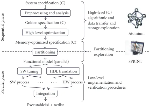
Figure1: Systematic C-based design flow.
from external estimation tool and can be annotated to the se-quential source code. The concurrent timed SystemC model provides valuable performance feedback to the designer in an early phase of the design flow.
SPRINT is part of a systematic C-based design flow tar-geting the implementation of advanced streaming applica-tions on multiprocessor platforms. It benefits from prepro-cessing and high-level optimizations applied to the C code before partitioning and support the independent develop-ment and testing, potentially by multiple team members in parallel, of parts of the application after partitioning.
SPRINT has been used for several multimedia designs, including an Embedded Zero Tree coder [9] and an MPEG-4 video encoder [10,11]. With SPRINT, the validation of the concurrent behavior of the complete design was obtained in less than six minutes, including the generation of the model itself. This fast verification path provides the possibility to identify conceptual design errors in an early stage of the de-sign, avoiding expensive design iterations and resulting is a significant speed-up of the design. Moreover, the automated generation of the concurrent model enables the exploration of different parallelization alternatives, ultimately resulting in an improved implementation of the embedded system.
The remainder of this paper is organized as follows. The next section provides an overview of the design flow used for both design cases. The functionality and implementation of the SPRINT tool is detailedSection 3, and experimental results for both design cases are given inSection 4.Section 5 gives a concise overview of related work and discusses the distinguishing features of our approach. The paper is closed with conclusions.
2. SYSTEMATIC DESIGN FLOW
Multimedia application code is usually provided by stan-dardization bodies like MPEG [12]. The provided code
typi-cally defines a wide range of options, which are the so-called profiles and levels. The primary goal of this code is to serve as a reference for verification of a realization of particular func-tionality or profile. The structure of the code is generally not immediately suited for implementation. Direct paralleliza-tion of this code for a multiprocessor platform leads to an inefficient software implementation, and direct HDL transla-tion is error-prone and lacks a modular testing environment. A systematic design approach starting with high-level opti-mizations and supporting parallelization and structured ver-ification is required.
Figure 1shows the applied design flow, starting from a system specification (typically reference code provided by an algorithm group or standardization body like MPEG) that will gradually be refined into the final implementation: a netlist with a set of executables. Two major phases are present: (i) a sequential phase where the initial specification is preprocessed, analyzed, and high-level optimized and (ii) a parallel phase in which the application is divided into paral-lel processes and refined to a register transfer level for hard-ware implementation or implementation code for softhard-ware implementation. The design flow consists of five logically se-quenced steps.
(1) Preprocessing and analysis prunes the reference code to retain only the required functionality for a given ap-plication profile. An initial complexity analysis identi-fies bottlenecks and points out the first candidates for optimization. This step is supported by the Atomium tool suite [13].
Sequential C code
void fetch(int∗A){ for (inti=0;i <64;i+ +)
int tmp; scanf(“%d”, & tmp); A[i]=tmp; } }
void process(int sum){ static int max=0; if (max<sum) max=sum; printf(“%d %d \n”, sum, max); }
int main(){
for (intn=0;n <100;n+ +){ int M[64], sum; fetch(M); add:{
sum=0;
for (inti=0;i <64;i+ +) sum +=M[i]; }
if (sum>128){ process(sum); }
} }
make task(fetch) make task(main::add) make task(process)
for (;;){ A→request(); for (i=0;i <64;i+ +){
scanf(“%d”, & tmp); A→write(tmp,i); }
A→commit(); }
for (;;){
sum=sum2→get(); if (max<sum) max=sum; printf(“%d %d \n”, sum, max); }
for (;;){ sum=0; A→request(); for (i=0;i <64;i+ +)
sum+=A→read(i); A→commit(); sum1→put(sum); }
for (;;){
for (n=0;n <100;n+ +){ sum=sum1→get(); if (sum>128){
sum2→put(sum); }
} } User directives
SPRINT
Fetch Add
Process
Main A[64]
SystemC
sum2
sum1
Figure2: A small example illustrating how SPRINT transforms sequential code to parallel SystemC code with user specified task bound-aries. The example includes block FIFO (A[64]) and scalar FIFO (sum1,sum2) channels including a channel (sum2) with a data-dependent communication rate.
This prepares the code for an efficient use of the com-munication primitives in the next step and facilitates parallelization.
(3) Partitioning splits the code into concurrent tasks and inserts the appropriate communication channels. This step is the focus of this paper. The design is partitioned into concurrent tasks for a combination of reasons, including throughput requirements, power require-ments (parallel processors can run at a lower clock rate), design complexity (small tasks are easier to im-plement, and hardware synthesis tools may yield better results) and the exploitation of heterogeneous proces-sors (tasks can be assigned to the best suited processor, or an efficient custom processor can be designed for a task).
(4) Software tuning and HDL translation refine each task of the partitioned system independently, either by mapping it to a target processor or by writing register transfer level HDL to be synthesized on an FPGA or as custom hardware. In addition, the communication channels between the tasks are mapped on the avail-able communication resources of the target platform. (5) Integration gradually combines and tests the refined
components to obtain a complete working system.
SPRINT supports the designer during the partition-ing step by automatically generatpartition-ing a concurrent model and inserting the appropriate communication primitives for designer-specified task boundaries. The generated model can be used to evaluate the partitioning before further refinement of the tasks. Alternatives can be evaluated by changing the task boundary directives and regenerating the model. This way, SPRINT eliminates the necessity to manually identify all accesses to the inputs and outputs of each task and in-sert the appropriate communication primitives. By
automat-ing this time-consumautomat-ing and error-prone task, SPRINT ef-fectively enables design space exploration. The task code in the generated model can also be used as a behavioral specifi-cation for the software refinement or hardware implementa-tion of a task. Finally, the model can be used to generate test stimuli and reference outputs to verify the implementation of each task separately.
3. THE SPRINT TOOL
The SPRINT tool automates the generation of a concurrent model. Based on task boundary directives provided by the designer, SPRINT transforms the sequential C program into a functionally equivalent concurrent SystemC model, con-sisting of tasks and communication channels.Figure 2shows the input and output of SPRINT for a small example. This section discusses five key issues in the design of the SPRINT tool: the type of parallelism extracted, the set of communi-cation primitives used, the available mechanisms for timing annotation, the user directives, and the implementation of the tool.
3.1. Type of parallelism
thus achieve a better load balance. However, it cannot exploit functional parallelism in which a loop body is split in parts containing different functionality to be executed on different processors.
The tasks generated by SPRINT represent functional par-allelism: each task implements a different subset of the state-ments in the application. By using functional parallelism, heterogeneous processors can be exploited. In case of cus-tom (hardware) processor design, a processor need only im-plement the functionality of a single task, thus leading to a smaller, more efficient processor that is easier to design and synthesize. Interiteration dependencies do not hinder the ex-traction of functional parallelism, but naturally lead to a pipelined execution. For this reason, functional parallelism extracted from a loop is often called pipelining. Functional parallelism can often be extracted in spite of the presence of uncounted loops, data-dependent control flow and hard to analyze array accesses. For these reasons, SPRINT only ex-tracts functional parallelism and leaves the extraction of data parallelism, when needed, to other tools to be applied during task refinement.
To distinguish the coarse-grain functional parallelism ex-tracted by SPRINT from fine-grained forms of functional parallelism such as instruction level parallelism (ILP) or soft-ware pipelining, we say that SPRINT uses task-level pipelin-ing. The tasks can be seen as pipeline stages communicating through FIFO-like channels.
3.2. Communication channels
Given the designer-specified task boundaries, SPRINT au-tomatically detects and inserts the required communication channels. SPRINT uses a restricted set of communication primitives with well-defined interface functions. The tasks only interact with the channels through these interface func-tions. The use of interface functions separates computation (in the tasks) from communication (in the channels). Thanks to this separation, tasks and channels can be refined indepen-dently.
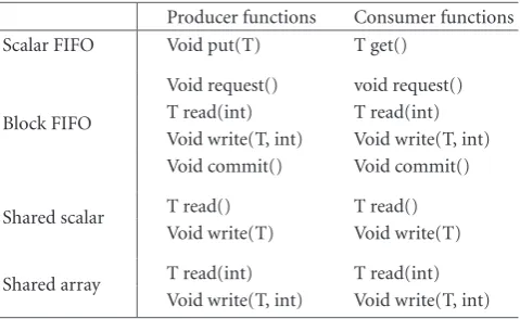
SPRINT uses two classes of communication channels: unidirectional point-to-point FIFO channels and shared data channels. Each channel has a set of interface functions with a well-defined behavior (Table 1). The implementation of the channel is left unspecified. In fact, different implementations may be used for different target platforms. A FIFO channel can be implemented using any available scheme that is con-sidered appropriate for the target platform, for example a custom hardware block, available synchronization primitives in a shared memory, RTOS primitives, busses or a packet switched network.
The default communication mechanism is a FIFO chan-nel. Two kinds of FIFO channels are used: scalar FIFO and block FIFO. A scalar FIFO uses the traditional put and get interface functions for the communication of scalar tokens. A block FIFO uses a nonstandard set of interface functions to enable zero-copy communication [18] for array tokens. The request function is blocking and waits until a token is available. The read and write functions allow random access to the current token. The commit function releases the
cur-Table1: Interface functions for the communication channels in-serted by SPRINT.
Producer functions Consumer functions Scalar FIFO Void put(T) T get()
Block FIFO
Void request() void request() T read(int) T read(int) Void write(T, int) Void write(T, int) Void commit() Void commit()
Shared scalar T read() T read() Void write(T) Void write(T)
Shared array T read(int) T read(int) Void write(T, int) Void write(T, int)
rent token, either (at the producer side) for transmission to the consumer or (at the consumer side) so that it can be re-cycled. Together, these functions allow an array token to be constructed in and read from the channel, without copying the array to or from local data. A scalar FIFO can be seen as a special case of a block FIFO, with array size one and using the traditional FIFO interface functions put and get. A put call is equivalent to a request-write-commit sequence, and a get call is equivalent to a request-read-commit sequence.
The use of a FIFO-like communication scheme is a log-ical choice for streaming applications. It naturally leads to a data-flow style implementation [19,20], with tasks implic-itly synchronized through FIFO channels. A task stalls when it needs a token from an empty input queue or when it tries to produce a token on a full output queue. The resulting implementation can be interpreted as a Kahn Process Net-work [21]. The behavior is deterministic: the outputs depend only on the inputs, and not on the relative order of execu-tion of the tasks. However, correct inserexecu-tion of FIFO channels such that the resulting Kahn Process Network is functionally equivalent to the original code is a nontrivial task that may require complicated data-flow analysis that is hard or even impossible to automate.
thus safeguard deterministic behavior. Functional correct-ness of the resulting parallel implementation must be verified by simulation of the transaction level model. A concrete ex-ample of the use of shared variables is given inSection 4.2.2.
3.3. Timing annotations
By default, SPRINT generates an untimed transaction level model. An untimed model may be sufficient to determine the functional correctness of a task partitioning, but an assess-ment of the quality of a task partitioning generally requires a timed model. In general, delays occur both in the application code (computation delays) and in the communication chan-nels (computation delays), but the approach used to insert these delays in the SystemC model differs.
To model computation delays, SPRINT can optionally insert wait calls in the generated SystemC code. The argu-ment of the wait call represents the processing time of the adjacent statements on the target platform.
The best way to estimate computation delays depends on the target platform, the available tools and the required accu-racy. Tools to profile execution times on specific processors exist [23–25]. In case of custom hardware, an experienced designer may be the only available source of high-level timing estimates. In both cases, the appropriate wait calls can be in-serted in the sequential source code. SPRINT will copy such wait calls to the generated SystemC model. The argument of the wait call can be a data dependent expression, thus pro-viding maximum flexibility.
Alternatively, SPRINT can insert symbolic delays during code generation. This method is based on counting the num-ber of operations of different types (read, write, addition, multiplication, . . . ) found in the C code. The operation count is then multiplied by a symbolic value representing the aver-age execution time for that type of operation on the target processor. An actual value must be provided when the gener-ated SystemC code is executed.
Communication delays are modeled in the SystemC im-plementation of the channel interface functions (Table 1). By default, a generic implementation is used. This generic im-plementation models blocking behavior of the FIFO chan-nels, but no communication delays. The generic implemen-tation can easily be replaced by a more detailed, platform spe-cific SystemC model with communication delays.
3.4. User directives
To facilitate the exploration of partitioning alternatives, user directives are not annotated in the sequential source code, but provided in a separate file. This avoids cluttering of the source code and allows a designer to maintain multiple di-rective files for the same design.
User directives refer to the source code using function names, labels, and variable names. There are three ways to select statements to be moved to a new task:
(i) make task(function)selects all statements in the
func-tion body;
(ii)make task(function::label)selects a single (but possibly
hierarchical) labeled statement; and
Sequential C program User directives
Abstract syntax tree
Control flow graph
Abstract syntax tree
SystemC 2.0 program 1. C parsing
2. Control flow extraction
4. Structured statement reconstruction
5. Code generation
3. Task creation
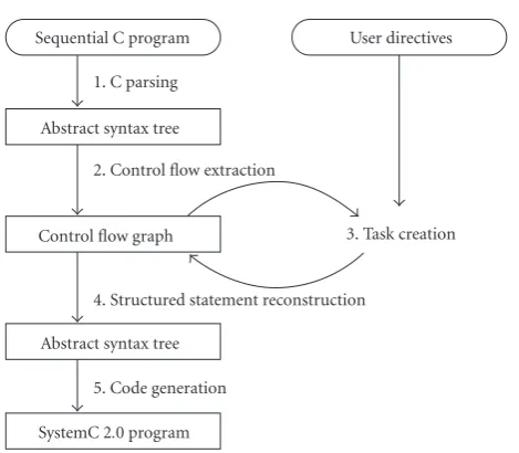
Figure3: SPRINT consists of five phases transforming a sequen-tial C program into a parallel SystemC program. The user provided input is indicated by rounded boxes and italics.
(iii) make task(function::label1-label2) selects all state-ments from label1 to label2 inclusive.
Each directive creates a new task. Together with the orig-inal “main” task,ndirectives result inn+ 1 tasks. By default, FIFO channels are inserted to all intertask communication. Shared data communication channels must be requested ex-plicitly using a shared variable(var) directive.
3.5. Implementation
As shown in Figure 3, the transformation is done in five phases.
(1) With C parsing, an abstract syntax tree (AST) is gener-ated.
(2) From this AST, a Control Flow Graph (CFG) is ex-tracted for each C function. Nodes correspond to ments, edges to control transfers. Structured state-ments (if-then-else, for and while loop, block, switch) are flattened. To aid variable liveness analysis, a spe-cial clear statement is automatically inserted where lo-cal variables in a block statement go out of scope; at that point, the local variable is known to be dead. (3) During task creation and based on the user directives,
the CFG is transformed to model the different concur-rent tasks. Channel access statements are inserted as required.
(4) After processing all directives again, an AST is gener-ated from the CFG using structured statement recon-struction techniques.
(5) Finally, the code for the concurrent SystemC model is generated.
not further discussed. Structured statement reconstruction is based on natural loops [26] and some heuristics; it is inpendent of how the input code was structured. A more de-tailed discussion is outside the scope of this paper.
Task creation
Task creation consists of the following seven steps that are executed for each make task directive. The result is a newly created task containing the statements selected in the user directive. These seven steps, together with the other phases inFigure 3, are implemented as fully automated routines of SPRINT.
Step 1 (single-entry single-exit check). Control flow edges
entering the group of statements selected by the make task directive are called entry edges; a statement at which such an edge ends is an entry statement. Similarly, control flow edges leaving the selected group of statements are called exit edges; a statement at which such an edge ends is an exit statement. SPRINT checks if there is only one entry and one exit state-ment for given task. If otherwise, a report is generated, pro-viding details to the designer, who can adjust the task bound-aries accordingly.
Step 2(single parent task check). The function containing
the selected statements is called the parent function of the new task. If the parent function is called in two or more parent tasks, channels to or from the new task will not be point-to-point. Such cases are not automatically handled by SPRINT, but a detailed report is generated for the designer.
Step 3 (split channel access check). Channel access
state-ments accessing the same channel must stay within the same task to guarantee the correct order of execution. They must either all stay in the parent task or all move to the new task. Since it is possible that channel access statements have been inserted in the parent task during a previous task creation, the requested task boundaries may cause channel accesses to become distributed over multiple tasks. In such a case, SPRINT does not proceed in task creation process. It gen-erates a report that provides details to the designer, who can adjust the task boundaries accordingly.
Step 4(identification of communication channels). In this
step, SPRINT identifies all base variables of the new task that will be changed into communication channels in the next steps. Due to the existence of pointers in C, it is not always immediately apparent from the source code which variables communicate data between the selected group of statements and the other statements of the parent task.
SPRINT distinguishes a variable reference from a variable access. A statement refers to a variable if the variable’s name is mentioned in the statement. It can either directly access (read or write) the variable, or take the address of the variable. A statement accesses a variable if it reads from or writes to the variable. Reads and writes can be direct or indirect (through a pointer). For example, the statementA[i] = tmp in the
sequential C code inFigure 2refers to the pointer variableA, but (indirectly) writes to the array variableM.
SPRINT identifies communication channels based on variable references, not accesses. This means that communi-cation channels can be identified prior to pointer analysis. A communication channel is inserted for each variable referred to by statements both inside and outside the selected group (Steps6and7). This means that a communication channel always corresponds to a user-named variable, which is called the base variable of the channel. For example, the pointer variableAinFigure 2is referenced both inside and outside the fetch task. Note that the make task(fetch) directive cre-ates a task containing the statements in thebodyof the fetch function, and that the declaration ofA is in the header of the function, so outside the task. A communication channel is therefore inserted forA, andAis the base variable of the channel.
Note that the need for a communication channel can al-ways be detected by looking at variable references only. In case of communication through an indirectly accessed loca-tion, a pointer to that location must have been communi-cated previously. If the communication of this pointer oc-curred through a named variable referenced both inside and outside the selected group of statements, that variable flags the presence of a communication channel. Otherwise, the pointer was communicated through an indirectly accessed location, and the same reasoning applies recursively. In the example ofFigure 2, data is communicated through the ar-ray variableM, but the need for a communication channel is detected by looking at references toA.
In the current implementation, a base variables must be a scalar, an array of scalars, a pointer to a scalar, or a pointer to an array of scalars, where a scalar is a variable that is not an array, struct or pointer. Examples of scalar types in C are int, unsigned char and float. In our experience, this restriction is not a serious limitation for the optimized sequential code for streaming applications to be processed by SPRINT, but it does allow us to use a fast tailored implementation of pointer and liveness analysis (Step 6).
Step 5(task creation). The new task consists of an infinite
loop containing the selected statements. In the parent task, the selected statements are removed and entry edges are set to point to the exit statement.
Step 6(pointer and liveness analysis). Liveness analysis
de-termines the direction of a FIFO channel to be inserted: an input FIFO is inserted for data that is live at an entry edge, and an output FIFO is inserted for data that is live at an exit edge (Step 7).
Modified C code
void fetch(int∗A){ for (inti=0;i <64;i+ +)
int tmp; scanf(“%d”, & tmp); A[i]=tmp; } }
void process(int sum){ static int max=0; if (max<sum) max=sum; printf(“%d %d\n”, sum, max); }
int main(){
for (intn=0;n <100;n+ +){ int M[64], sum, N[64]; fetch(M); fetch(N); add:{
sum=0;
for (inti=0;i <64;i+ +) sum +=M[i]+N[i]; }
if (sum>128){ process(sum); }
} }
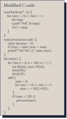
Figure4: Modified sequential C code ofFigure 2illustrating the problem of a base variableAthat can point to multiple locations.
In the presence of pointers, liveness analysis relies on pointer analysis to identify all accesses (including indirect accesses) to a given location. Note that pointers automat-ically arise in C when an array is passed as a parame-ter to a function: C automatically converts the array pa-rameter to a pointer papa-rameter. This is a common sit-uation in C code for multimedia applications. We per-form an inter-procedural context-insensitive flow-insensitive Andersen-style [27] pointer analysis for all potential targets of a pointer base variable. Potential targets of pointer base variables are all scalar and array of scalar variables. Heap lo-cations are not analyzed; if a base variable can refer to a heap location, a report is generated the designer, who can take cor-rective action.
If the base variable of a channel can point to more than one location, and at least one of these locations is an array, an additional context-sensitive analysis is performed to ver-ify that the target locations are never live at the same time. This is a necessary condition for the use of zero-copy chan-nels (shared array and block FIFO, seeSection 3.2). To avoid the overhead of a general context-sensitive analysis, this anal-ysis is only done for the potential targets of a pointer base variable. If the condition is not fulfilled, a report is generated providing details for the designer, who can than adjust the code appropriately, taking design constraints into account.
To illustrate the problem of a base variable pointing to multiple locations, assume that the sequential code in Figure 2is modified such that it contains a second call to the fetch function, as inFigure 4. NowAcan point toMorN, andMandNare live at the same time. Since the block FIFO channelAcannot contain bothMandNat the same time,M andNwould have to be communicated one by one. Since a task can only access one token at a time in a given block FIFO channel, the first array would then have to be copied out of the channel into a temporary buffer before the second array could be accessed. In general, the copying cancels the effect
of zero-copy communication and may ruin high-level mem-ory optimizations applied during the sequential phase of our systematic design flow (Section 2). For this reason, we prefer to ask the designer to take appropriate action.
Step 7(channel insertion). For each base variable, a channel
is inserted. The kind of channel depends on user directives (for shared data) and on the type of the communicated data.
(1) A shared data channel is inserted only if the base able is marked as shared by a user directive. If the base vari-able is an array, or if it is a pointer and at least one location pointed to is an array, a shared array channel is inserted. Oth-erwise, a shared scalar is inserted. All accesses to the chan-nel data, including indirect accesses, are replaced by read() and write() operations on the channel. The simple example inFigure 2does not contain shared data channels, but three examples of shared data channels in an MPEG-4 encoder will be discussed further (Section 4.2).
(2) Otherwise, if the base variable is an array, or if it is a pointer and at least one location pointed to is an array, a block FIFO is inserted. To avoid array copying, the data to be communicated will be constructed directly in the array. This means that every access to the array is replaced by a read() or write() operations on the block FIFO. If a pointer derefer-ence may access more than one location, all the locations it may access must be part of the same block FIFO channel, so that the access can be replaced by a single read() or write() operations. In addition, a request() call is inserted before the first access and a commit() call is inserted after the last access, both in the new task and in the parent task. To maximize par-allelism and decrease the probability of split channel access problems (Step 3), code motion is used to move the request() and commit() calls as close as possible to the data accesses.
In the example ofFigure 2,A[i] = tmp is replaced by
A->write(tmp,i) and sum += M[i] is replaced by sum +=
A->read(i) during processing of the make task(fetch) di-rective. Due to code motion, the A->request() and
A->commit() calls in the parent task are moved into the block labeled add, just before and after the for-loop, respec-tively. During processing of the make task(main::add) direc-tive, theA->request() andA->commit() calls are moved to the add task, together with the other statements in the block. Without code motion, these calls would have stayed outside the block, and the split channel access check (Step 3) would have failed.
The direction of the FIFO depends on the results of live-ness analysis (Step 6). If channel data is only live at an entry edge of the new task, a channel is created from the parent task to the new task, and vice versa. If channel data can be live both at an entry edge and at an exit edge, a report is gen-erated to the designer, who can take corrective action. An au-tomatic solution would involve copying of arrays, which is to be avoided.
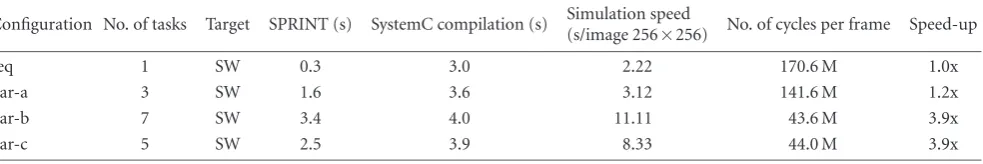
Table2: Experimental results for the EZT coder (801 lines of sequential C code).
Configuration No. of tasks Target SPRINT (s) SystemC compilation (s) Simulation speed(s/image 256
×256) No. of cycles per frame Speed-up
seq 1 SW 0.3 3.0 2.22 170.6 M 1.0x
par-a 3 SW 1.6 3.6 3.12 141.6 M 1.2x
par-b 7 SW 3.4 4.0 11.11 43.6 M 3.9x
par-c 5 SW 2.5 3.9 8.33 44.0 M 3.9x
the consumer task before the first access. To maximize par-allelism and decrease the probability of split channel access problems (Step 3), code motion is used to move the put() and get() calls as close as possible to the data accesses. Exam-ples of scalar FIFO channels inFigure 2are sum1 and sum2.
4. EXPERIMENTAL RESULTS
To asses the usability of SPRINT, the following questions must be answered.
(1) Can SPRINT effectively parallelize real applications on realistic platforms?
(2) Is the evaluation of a partitioning, including model generation, compilation and simulation, fast enough to support interactive exploration of the design space?
To obtain answers to these questions, we have applied SPRINT on two multimedia designs: an Embedded Zero Tree Coder (about 800 lines of sequential C code) and an MPEG-4 Simple Profile Video Encoder (about 10000 lines of sequen-tial C code). A description of these designs and how they were parallelized is given below. The results are summarized in Tables2and3. All results were obtained on a Pentium 4 3.20 GHz with 1 GB RAM running RedHat Linux 2.4.21 with gcc 3.2.3, SystemC 2.1 and SPRINT 2.8.13. Reported execu-tion times are elapsed times on an otherwise unloaded pro-cessor.
4.1. Embedded zero-tree coder
Embedded Zero Tree (EZT) coding is a recursive compres-sion scheme for wavelet coefficients [28,29]. It is used for image compression in MPEG-4 standard for Visual Texture Coding [12] for 3D modeling. In contrast to the well-known MPEG-4 video coding, this is an image coding application.
The sequential C code used in this test case has been taken from the design data of the OZONE chip [9]. The preprocessing and high-level optimization phases of our sys-tematic design flow had already been applied to this code. During optimization, the recursive core of the reference code was replaced by two iterative passes: a code definition pass and a code production pass. This transformation facilitates memory optimizations and at the same time enables a par-allel implementation of the two passes. For hardware imple-mentation, the code was then partitioned in three pipelined tasks: code definition, code production and arithmetic
cod-ing. A detailed explanation of the EZT algorithm [28,29] and the optimizations applied for hardware implementation [9] is beyond the scope of this paper.
We have used SPRINT to explore a software mapping for this design on a multiprocessor platform. For timing, we used SPRINT’s automatic insertion of wait statements, and assumed that every operation takes one clock cycle. The generic implementation of the communication chan-nels, with zero communication delay, was used.
Three partitioning configurations have been evaluated. In configuration par-a, SPRINT creates the same three tasks that were used in the hardware implementation. Simulation results (Table 2) for a 256×256 pixels version of the well-known Lena image show that a speed-up factor of only 1.2x is achieved. An examination of the task activity diagram re-veals that the bottleneck is the code definition task. This task mainly performs bit manipulations that are comparatively slower in software than in hardware. In configuration par-b, the code definition task was therefore further parallelized by splitting of four additional tasks. The resulting task dia-gram is shown inFigure 5. Assuming one processor per task, a speed-up of 3.9x can now be achieved on 7 processors. The task activity diagram for this configuration (Figure 6) shows that the processors for the code definition task and the arith-metic coder task are barely loaded. In configuration par-c, the task boundaries are therefore changed so that the code definition functionality is in the same task as the compute code3 functionality, and the arithmetic coder functionality is in the same task as the code production functionality. This configuration achieves practically the same speed up on just five processors.
The execution times for SPRINT model generation, Sys-temC compilation and the simulation speed are listed in Table 2. A new configuration for this 800 line example can be evaluated in less than one minute. This is more than fast enough to allow interactive exploration.
4.2. MPEG-4 simple profile video encoder
Compute code0
Compute code1
Compute code2
Compute code3 Code definition
Code
production Arithmeticcoder Detail
image
Codes Syms Bits
Figure5: Task diagram for configuration par-b of the EZT coder. Thin lines are scalar FIFOs and thick lines are block FIFOs.
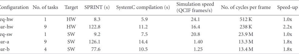
Table3: Experimental results for different parallelizations of the MPEG-4 simple profile encoder.
Configuration No. of tasks Target SPRINT (s) SystemC compilation (s) Simulation speed
(QCIF frames/s) No. of cycles per frame Speed-up
seq-hw 1 HW 8.3 5.9 24.1 512 K 1.0x
par-hw 9 HW 122.8 11.2 16.4 238 K 2.2x
seq-sw 1 SW 9.2 7.5 20.8 23.9 M 1.0x
par-a 9 SW 126.1 14.4 1.40 13.3 M 1.8x
par-b 4 SW 77.6 10.5 1.25 13.4 M 1.8x
4.2.1. Functionality, preprocessing, and high-level optimizations
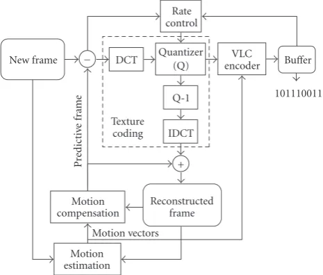
The MPEG-4 part 2 video codec [31] belongs to the class of lossy hybrid video compression algorithms [32].Figure 7 gives a high-level view of the encoder. A frame is divided in macroblocks, each containing 6 blocks of 8×8 pixels: 4 lu-minance and 2 chrolu-minance blocks. The motion estimation (ME) exploits the temporal redundancy by searching for the best match for each new input block in the previously recon-structed frame. The motion vectors define this relative po-sition. The remaining error information after motion com-pensation (MC) is decorrelated spatially using a DCT trans-form and is then quantized (Q). The inverse operationsQ−1 and IDCT (completing the texture coding chain) and the motion compensation reconstruct the frame as generated at the decoder side. Finally, the motion vectors and quantized DCT coefficients are variable length encoded. Completed with video header information, they are structured in packets in the output buffer. A rate control algorithm sets the quan-tization degree to achieve a specified average bit rate and to avoid over or under flow of this buffer.
A discussion of all the optimizations applied during the sequential phase of our systematic design flow (Section 2) is beyond the scope of this paper, but one particular optimiza-tion is relevant to illustrate the use of shared data channels in SPRINT. The original specification contains two frame buffers for the reconstructed frame (Figure 7), to allow mo-tion estimamo-tion and momo-tion compensamo-tion to access the cur-rent frame while the next frame is constructed. However, as frame buffers are large and costly, only a single frame buffer is retained. As long as motion estimation and com-pensation process the frame in a row-by-row order and the update of the frame happens in the same order, it is
suffi-cient to prefetch the pixels needed for motion estimation and compensation and store them in a separate, smaller buffer before they are overwritten. As a high-level optimization, the sequential C code has been modified to implement this prefetching and remove the double frame buffer.
4.2.2. Partitioning for hardware mapping
To achieve the high throughput requirement (47520 mac-roblocks/s, equivalent to 18.25 megapixels/s) at a low-power consumption [30], a video pipeline architecture is envisaged exploiting the inherent functional parallelism of the encod-ing algorithm. Every functional unit becomes a separate stage of the pipeline, and is implemented as a task specific proces-sor, except for the rate control task, which is implemented as a software task to be executed on an embedded processor. Each channel is implemented as an on-chip two-port mem-ory, except for the reconstructed frame buffer that is assigned to an external memory.
Before moving to the (work intensive) register transfer level implementation of the processors, a SystemC transac-tion level model was generated by SPRINT. The partitransac-tioning used for this design consists of 9 tasks (Figure 8). To model timing, wait statements were manually added to the code of each task by an experienced designer, based on the expected number of memory accesses and processing cycles for the corresponding processor. The model was used to verify func-tional correctness, to assess the achieved parallelism and to generate a test bench per task, allowing verification of the register transfer level implementation of each processor.
Figure6: Extract of the task activity diagram generated during simulation of the EZT coder in configuration par-b.
Rate control
Texture coding
Motion vectors
Pr
ed
ic
ti
ve
fr
ame
New frame − DCT Quantizer(Q) encoderVLC Buffer
101110011 Q-1
IDCT
+
Reconstructed frame Motion
compensation
Motion estimation
Figure7: Functional view of an MPEG-4 video encoder.
YUV buffer. Shared data channels provide no tion. Under certain conditions, however, the synchroniza-tion of shared data accesses is redundant due to the presence of FIFO channels between the same tasks (see [22, Chapter 9]). SPRINT cannot verify that these conditions are fulfilled, but the designer can use the generated concurrent model to check the correct synchronization through simulation.
Consider for example the search area channel between the copy controller and the motion estimation (Figure 8). When motion estimation advances to the next block, the new search area overlaps the previous search area (Figure 9). For efficiency reasons, the overlapping part of the search area is reused, and only the nonoverlapping part is written by the copy controller. This access scheme was introduced as a high-level memory optimization during the sequential phase of the design flow. As a regular FIFO does not support data reuse, the search area communication channel has been im-plemented as a circular buffer in a shared data channel.
In the sequential code, the copy controller and the mo-tion estimamo-tion execute in turn. In the concurrent model, however, this is no longer true, the second execution of the copy controller can start during or even before the first exe-cution of the motion estimation. This means that the size of the search area buffer must be increased so that it can hold the data produced by two or more executions of the copy
controller, as well as reused data. The required size is limited by the depth of the scalar FIFO from copy controller to mo-tion estimamo-tion. Every execumo-tion of the copy controller also produces a token on this FIFO. When the FIFO is full, the copy controller will block until the motion estimation has executed at least once. If the depth of the FIFO isN, the copy controller can be a mostNexecutions ahead of the motion estimation.
A similar reasoning can be made about the synchroniza-tion of accesses to the YUV buffer and the reconstructed frame. In these two cases, there is no direct FIFO between the tasks accessing the shared data, but there is in both cases an indirect path consisting of FIFOs only. Such an indirect path can also provide sufficient synchronization; the maxi-mum lag between the producing and consuming tasks is re-lated to the sum of the depths of the FIFOs on the path. In general, a necessary (but not sufficient) condition for correct synchronization of shared data accesses is that there is a di-rect or indidi-rect path consisting of FIFO channels between the tasks accessing the shared data. This condition is checked by SPRINT.
The amount of data produced by the copy controller is variable in our design. Usually, three macroblocks are pro-duced, but at the edges of the frame, there are more. At a cer-tain moment during the design process, this was not taken into account. The problem could not be detected by execut-ing the sequential code. Without the concurrent model gen-erated by SPRINT, this synchronization problem would only have been detected during integration of the register transfer level code of the processors, and a fix would have been much more costly.
4.2.3. Partitioning for software mapping
Copy controller
Texture update
Motion
estimation compensationMotion
Texture coding
Input
Controller Entropy
coding
Bitstream packetization Software
orchestrator
Reconstructed frame Compensated
block Buffer
YUV Search
area New
macroblock From
capture
card Current
macroblock
Error block
Texture block
Quantized macroblock Motion
vectors
Metrics
Done-setup
Done-frame
Parameter settings
Output bitstream
Figure8: Task diagram for the par-hw and par-a configurations of the MPEG-4 simple profile encoder. Thin lines are scalar FIFOs, thick lines are block FIFOs, and dotted lines are shared variables. To avoid cluttering the diagram, parameter setting channels are shown only partially.
Figure9: Data reuse in the overlapping region of the search area for motion estimation.
context switching overhead on the second processor, the mo-tion compensamo-tion, texture update, texture coding, entropy coding and bit-stream packetization functions were imple-mented as a single task. Merging the software orchestrater with this task proved undesirable, because it introduced a se-quence constraint that reduced the effective parallelism. The final configuration contains four tasks: a motion estimation task, a DMA task implementing input controller and copy controller, a software orchestrater task and a task implement-ing the remainimplement-ing functional blocks.
4.2.4. Results
Results for both hardware and software partitioning are sum-marized in Table 3. The seq-hw and seq-sw configurations correspond to a sequential execution with timing for the hardware and software implementations, respectively, and are used as a reference point to evaluate the achieved speed-up. Simulation speed was measured using the Foreman QCIF test sequence containing 299 frames.
The processing speed observed during simulation of the par-hw configuration (238 Kcycles/frame) is close to the processing speed measured on the hardware implementa-tion [10] (3.2 MHz for 15 frames/s QCIF, corresponding to
213 Kcycles/frame), indicating that the timing estimates used were realistic. The speed-up obtained for this configuration is only 2.2x for nine processors, but this is not a problem as the target of the partitioning was not to obtain the high-est possible throughput, but low-power consumption and an efficient design process. The partitioning used results in rela-tively simple processors for which an energy-efficient imple-mentation is possible. These processors consume practically no power when idle. Also, smaller processors are easier to de-scribe in VHDL and are handled more efficiently by synthesis tools. In addition and thanks to the separation of computa-tion and communicacomputa-tion, multiple designers can work on the refinement of these processors in parallel.
Starting from 9588 lines of sequential C code and user-defined task boundaries for up to nine tasks, SPRINT can generate a concurrent SystemC model in about two minutes. The simulation of a complete QCIF sequence (299 frames) for the hardware partitioning (par-hw configuration) is fin-ished in less than 20 seconds. In comparison, simulation with the Modelsim VHDL simulator, only possible after comple-tion of the HDL design of the encoder system, requires more than 6 hours for the same QCIF sequence. Simulation speed for the software configurations is an order of magnitude slower than for the hardware configurations. This is due to the more detailed timing annotations used in the software configurations. Even in the slowest configuration (par-b), a simulation of the complete test sequence takes only 4 min-utes.
Table4: A comparison of SPRINT with related approaches.
Input Partitioning Data-flow analysis Output
COMPAAN ANLP Automatic Static, array YAPI KPN
FP-MAP C Automatic Dynamic None
DSWP C Automatic Static, recursive data structures Itanium object code
SPRINT C User-defined Static, scalar SystemC TLM
QCIF test sequence is less than six minutes. We believe that this is more than fast enough to allow interactive exploration of the design space.
5. RELATED WORK
Parallel computing and parallelization are wide research ar-eas that have been studied in a large number of projects. Due to this broad scope, we only list the most closely related ap-proaches that have focused on the task-level pipelining.
Starting from an initial sequential implementation (of a given application, typically written in C), two general ap-proaches to multiprocessor partitioning are manual refine-ment and automated parallelization. The manual approach to embedded system mapping is typically based on a sys-tematic methodology [33]. This, however, is a difficult and error-prone process, as shown in [34]. The final solution can be very optimal for given platform, but is typically very platform-specific, hard to adapt and maintain. Moreover, a complete rewriting or a new solution has to be developed for other platforms.
Another manual approach to multiprocessor partition-ing is the use of higher level programmpartition-ing languages that express parallelism in an explicit form, for example, paral-lel languages with support for task-level pipelining as ZPL [35], or more specialized languages, for example, streaming languages as StreamC [36] or KernelC [37]. Use of such lan-guages, accompanied with an effective compiler and an ap-propriate back-end for given platform, can considerably sim-plify the exploration and mapping process. Even though this approach can lead to solutions with good performance (as re-ported in [34] for ZPL), it still requires manual code rewrit-ing from the initial implementation to the chosen program-ming language, which is a nontrivial task.
Automated parallelization in general requires either ad-vanced compilers [15–17,38] or source-to-source transfor-mation tools [39]. Even though the topic of automated par-allelization has been researched for decades, the problem of effective code parallelization seems to persist. Further-more, only very few approaches, such as IBM X1 HPF [38], have implemented support for task-level pipelining, while the most advanced compilers, such as SUIF [15], have fo-cused on advanced program analysis and transformations for data parallelism.
The IBM X1 HPF compiler [38] and its derivatives are to our knowledge the only compilers that automatically per-form functional pipelining without user annotations to the input code (HPF). As reported in [34], the compiler per-forms well, yet only on a limited number of kernels. It does
not pipeline non-perfectly nested loops, or more complex control-flow that could still be pipelined with a minor user intervention. Similar restrictions/results seem to be very common also for the other automated approaches to paral-lelization.
The approaches that are most closely related to SPRINT are COMPAAN, FP-MAP, and DSWP. Like SPRINT, they use task-level pipelining to parallelize embedded applications. The key features of these approaches are compared inTable 4. COMPAAN [40,41] automatically creates a task (or pro-cess) for each function call in an affine nested loop pro-gram (ANLP) written in MATLAB syntax. Using the results of an exact array data-flow analysis, array inputs and outputs are converted to special optimized FIFOs that can reorder and/or duplicate tokens as necessary. The output represen-tation generated by COMPAAN is a Kahn Process Network (KPN). One of the limitations of this approach is that the structure of the ANLP determines the task boundaries; to ob-tain a different partitioning, the source code must be edited. Task boundaries cannot be located in code executed under nonlinear or data-dependent conditions. This restricts the usability of COMPAAN to only ANLP input, which reduces its practicality by processing only to specific, well-formed loops.
FP-MAP [42] accepts arbitrary C code and is not lim-ited to ANLP as COMPAAN. It automatically distributes the statements of a given loop nest over a given number of pro-cessors, minimizing the initiation interval of the pipeline. The distribution algorithm relies on estimates of execution times and branch execution probabilities obtained via pro-filing. Execution times are assumed to be independent of the processor, and the cost and feasibility of the resulting communication on the target platform is not taken into ac-count. The data-flow analysis used in FP-MAP is dynamic: data dependences are registered during execution of the C code for a given set of inputs. This means that FP-MAP can analyze data flow for arbitrary control flow including data-dependent conditions and for arbitrary index expres-sions. FP-MAP does not automatically insert communica-tion channels or generate code; the result is an assignment of statements to processors. Thus, it is an interesting approach to task-level pipelining, yet it is not a practical tool usable for mapping real-life multimedia programs to multiproces-sor embedded systems.
Strongly-Connected Components (SCC) in the dependence graph of the input program. Such an SCC must not be split to ensure unidirectional flow of dependences between the re-sulting tasks. Similar to FP-MAP, a load balancing heuristic is used to distribute the SCCs over the pipeline stages (tasks). DSWP uses the so-called synchronization array for commu-nication among threads [44]. The synchronization array is dedicated hardware that implements a simple FIFO chan-nel. The approach leverages prior research on instruction level parallelism (ILP) by utilizing an existing compilation framework, the impact compiler. Thus, it has a back-end that is currently targeting the itanium processors. Some of the disadvantages of this approach are missing communication optimization, no support for source-to-source transforma-tion, and no possibility of user interaction that we believe is needed for exploration of the solution space for optimized application mapping.
SPRINT provides a unique combination of features that is especially suited to explore the partitioning of an embed-ded streaming application. It accepts any ANSI-C code. Task boundaries are defined by the designer, which is an advantage given the less than ideal results obtained with existing au-tomatic parallelization tools. The required communication channels are automatically detected and inserted using well-known, robust, and fast scalar data-flow analysis techniques. These techniques are sufficiently powerful to handle com-plex real-life applications with nonlinear index expressions and data-dependent conditions. In our design flow, sequen-tial optimization steps precede the partitioning, which facili-tates the flow analysis. If desired, a more advanced data-flow analysis can be used instead. Finally, SPRINT generates a concurrent transaction level model that can be used to in-teractively explore alternative solutions and rapidly evaluate their performance. The generated model is also suitable for further automated of manual refinement. To the best of our knowledge, SPRINT is the first tool to generate a concurrent transaction level model from sequential ANSI-C code.
6. CONCLUSIONS
To support our systematic C-based design flow for ad-vanced multimedia applications with stringent performance and power requirements, we have developed a tool called SPRINT that generates a concurrent SystemC transaction level model starting from sequential C code and user-selected task boundaries. This tool automates the time-consuming and error-prone task of manually creating such a model, thus encouraging the designer to extensively explore alternative partitionings and avoid the premature selection of a subopti-mal implementation. To the best of our knowledge, SPRINT is the first tool to generate a concurrent transaction level model from sequential C code.
To match the characteristics of the target applications and enable effective exploitation of heterogeneous target plat-forms, SPRINT uses task level pipelining and a carefully se-lected set of FIFO-like communication channels. The imple-mentation can handle full ANSI-C code and relies on selec-tive and tuned program analysis techniques to achieve a high performance.
The effectiveness of the SPRINT tool has been experi-mentally verified by applying it to two designs: an Embed-ded Zero Tree Coder (800 lines of sequential C code) and an MPEG-4 Simple Profile Encoder (10000 lines of sequential C code). For both designs, multiple concurrent models for different realistic target platforms, including both hardware and software platforms, have been generated and evaluated. In all cases tried, the model could be generated, compiled and evaluated in less then six minutes. This is fast enough to allow extensive exploration of the design space.
ACKNOWLEDGMENT
The authors would like to thank Henk Corporaal for the in-sightful discussions and his valued contribution to this paper.
REFERENCES
[1] M. Horowitz, T. Indermaur, and R. Gonzalez, “Low-power digital design,” inProceedings of the IEEE Symposium on Low Power Electronics, pp. 8–11, San Diego, Calif, USA, October 1994.
[2] M. Horowitz, E. Alon, D. Patil, S. Naffziger, R. Kumar, and K. Bernstein, “Scaling, power, and the future of CMOS,” in Pro-ceedings of IEEE International Electron Devices Meeting (IEDM ’05), p. 7, Washington, DC, USA, December 2005.
[3] H. De Man, F. Catthoor, G. Goossens, et al., “Architecture-driven synthesis techniques for VLSI implementation of DSP algorithms,”Proceedings of the IEEE, vol. 78, no. 2, pp. 319– 335, 1990, special issue on the future of computer-aided de-sign.
[4] T. H. Meng, B. M. Gordon, E. K. Tsern, and A. C. Hung, “Portable video-on-demand in wireless communication,” Pro-ceedings of the IEEE, vol. 83, no. 4, pp. 659–680, 1995, special issue on low power electronics.
[5] A. Lambrechts, P. Raghavan, A. Leroy, et al., “Power break-down analysis for a heterogeneous NoC platform running a video application,” in Proceedings of the 16th IEEE Interna-tional Conference on Application-Specific Systems, Architectures and Processors (ASAP ’05), pp. 179–184, Samos, Greece, July 2005.
[6] M. A. Viredaz and D. A. Wallach, “Power evaluation of a hand-held computer,”IEEE Micro, vol. 23, no. 1, pp. 66–74, 2003. [7] L. Cai and D. Gajski, “Transaction level modeling in system
level design,” Tech. Rep. 03-10, CECS, University of California, Irvine, Calif, USA, 2003.
[8] http://www.systemc.org/.
[9] B. Vanhoof, M. Peon, G. Lafruit, J. Bormans, M. Engels, and I. Bolsens, “A scalable architecture for MPEG-4 embedded zero tree coding,” inProceedings of the 21st IEEE Annual Custom In-tegrated Circuits Conference (CICC ’99), pp. 65–68, San Diego, Calif, USA, May 1999.
[10] K. Denolf, C. De Vleeschouwer, R. Turney, G. Lafruit, and J. Bormans, “Memory centric design of an MPEG-4 video en-coder,”IEEE Transactions on Circuits and Systems for Video Technology, vol. 15, no. 5, pp. 609–619, 2005.
[12] http://www.mpeg.org/.
[13] Atomium,http://www.imec.be/atomium.
[14] F. Catthoor, E. de Greef, and S. Suytack,Custom Memory Man-agement Methodology, Kluwer Academic Publishers, Boston, Mass, USA, 1998.
[15] M. W. Hall, J. M. Anderson, S. P. Amarasinghe, et al., “Maxi-mizing multiprocessor performance with the SUIF compiler,”
Computer, vol. 29, no. 12, pp. 84–89, 1996.
[16] D. A. Padua and M. J. Wolfe, “Advanced compiler opti-mizations for supercomputers,”Communications of the ACM, vol. 29, no. 12, pp. 1184–1201, 1986, special issue.
[17] M. E. Wolf and M. S. Lam, “A loop transformation theory and an algorithm to maximize parallelism,”IEEE Transactions on Parallel and Distributed Systems, vol. 2, no. 4, pp. 452–471, 1991.
[18] D. R. Cheriton, “The V distributed system,”Communications of the ACM, vol. 31, no. 3, pp. 314–333, 1988.
[19] E. A. de Kock, G. Essink, W. J. M. Smits, et al., “YAPI: appli-cation modeling for signal processing systems,” inProceedings of the 37th Design Automation Conference (DAC ’00), pp. 402– 405, Los Angeles, Calif, USA, June 2000.
[20] W. A. Najjar, E. A. Lee, and G. R. Gao, “Advances in the dataflow computational model,”Parallel Computing, vol. 25, no. 13-14, pp. 1907–1929, 1999.
[21] G. Kahn, “The semantics of simple language for parallel pro-gramming,” inProceedings of the IFIP Congress on Information Processing, J. L. Rosenfeld, Ed., pp. 471–475, North-Holland, Stockholm, Sweden, August 1974.
[22] S. Sriram and S. S. Bhattacharyya,Embedded Multiprocessors: Scheduling and Synchronization, Marcel Dekker, New York, NY, USA, 2000.
[23] R. Eigenmann and P. McClaughry, “Practical tools for opti-mizing parallel programs,” inProceedings of the SCS Multicon-ference, Arlington, Va, USA, March-April 1993.
[24] I. Park, M. J. Voss, B. Armstrong, and R. Eigenmann, “In-teractive compilation and performance analysis with ursa mi-nor,” inProceedings of the 10th International Workshop on Lan-guages and Compilers for Parallel Computing, pp. 163–176, Minneapolis, Minn, USA, August 1997.
[25] D. A. Reed, P. C. Roth, R. A. Aydt, et al., “Scalable performance analysis: the Pablo performance analysis environment,” in Pro-ceedings of the Scalable Parallel Libraries Conference, pp. 104– 113, Mississippi State, Miss, USA, October 1993.
[26] A. Aho, R. Sethi, and J. D. Ullman,Principles of Compiler De-sign, Addison-Wesley, Reading, Mass, USA, 1986.
[27] L. O. Andersen,Program analysis and specialization for the C programming language, Ph.D. thesis, Computer Science De-partment, University of Copenhagen, Copenhagen, Denmark, May 1994.
[28] J. M. Shapiro, “Embedded image coding using zero trees of wavelet coefficients,”IEEE Transactions on Signal Processing, vol. 41, no. 12, pp. 3445–3462, 1993.
[29] J. M. Shapiro, “A fast technique for identifying zero trees in the EZW algorithm,” inProceedings of the IEEE Interna-tional Conference on Acoustics, Speech, and Signal Processing (ICASSP ’96), vol. 3, pp. 1455–1458, Atlanta, Ga, USA, May 1996.
[30] K. Denolf, A. Chirila-Rus, and D. Verkest, “Low-power MPEG-4 video encoder design,” in Proceedings of the IEEE Workshop on Signal Processing Systems Design and Implementa-tion (SIPS ’05), pp. 284–289, Athens, Greece, November 2005. [31] “Information technology-Generic coding of audio-visual
objects—part 2: visual,” ISO/IEC 14496-2:2004, June 2004.
[32] V. Bhaskaran and K. Konstantinides,Image and Video Com-pression Standards: Algorithms and Architectures, Kluwer Aca-demic Publishers, Boston, Mass, USA, 1997.
[33] A. C. Downton, R. W. S. Tregidgo, and A. Cuhadar, “Top-down structured parallelization of embedded image process-ing applications,” IEE Proceedings-Vision, Image and Signal Processing, vol. 141, no. 6, pp. 431–437, 1994.
[34] E. C. Lewis and L. Snyder, “Pipelining wavefront computa-tions: experiences and performance,” inProceedings of the 5th IEEE International Workshop on High-Level Parallel Program-ming Models and Supportive Environments (HIPS ’00), pp. 261–268, Cancun, Mexico, May 2000.
[35] L. Snyder,A Programmer’s Guide to ZPL, MIT Press, Cam-bridge, Mass, USA, 1999.
[36] A. Das, W. J. Dally, and P. Mattson, “Compiling for stream pro-cessing,” inProceedings of the 15th International Conference on Parallel Architectures and Compilation Techniques (PACT ’06), pp. 33–42, Seattle, Wash, USA, September 2006.
[37] P. Mattson, W. J. Dally, S. Rixner, U. J. Kapasi, and J. D. Owens, “Communication scheduling,” inProceedings of the 9th Inter-national Conference on Architectural Support for Programming Languages and Operating Systems (ASPLOS ’00), pp. 82–92, Cambridge, Mass, USA, November 2000.
[38] M. Gupta, S. Midkiff, E. Schonberg, et al., “HPF compiler for the IBM SP2,” inProceedings of the ACM/IEEE Supercomput-ing Conference, vol. 2, pp. 1944–1984, San Diego, Calif, USA, December 1995.
[39] D. B. Loveman, “Program improvement by source-to-source transformation,”Journal of the Association for Computing Ma-chinery, vol. 24, no. 1, pp. 121–145, 1977.
[40] T. Stefanov, C. Zissulescu, A. Turjan, B. Kienhuis, and E. De-prettere, “Compaan: deriving process networks from Matlab for embedded signal processing architectures,” inProceedings of the International Conference on Design Automation and Test in Europe, Paris, France, February 2004.
[41] A. Turjan, B. Kienhuis, and E. Deprettere, “Translating affine nested-loop programs to process networks,” inProceedings of the International Conference on Compilers, Architecture, and Synthesis for Embedded Systems, pp. 220–229, Washington, DC, USA, September 2004.
[42] I. Karkowski and H. Corporaal, “FP-map - an approach to the functional pipelining of embedded programs,” inProceedings of the 4th International Conference on High Performance Com-puting (HiPC ’97), pp. 415–420, Bangalore, India, December 1997.
[43] G. Ottoni, R. Rangan, A. Stoler, M. J. Bridges, and D. I. Au-gust, “From sequential programs to concurrent threads,”IEEE Computer Architecture Letters, vol. 5, no. 1, pp. 6–9, 2006. [44] R. Rangan, N. Vachharajani, M. Vachharajani, and D. I.
Au-gust, “Decoupled software pipelining with the synchroniza-tion array,” in Proceedings of the 13th International Con-ference on Parallel Architectures and Compilation Techniques (PACT ’04), pp. 177–188, Antibes Juan-les-Pins, France, September-October 2004.
including a schematic editor, the core data structure of DSP sta-tion behavioral synthesis tool suite and a dynamic data-flow sim-ulator. He was an early adopter of object-oriented programming techniques in general and the C++ programming language in par-ticular. In 1996, he joined the Design Technology for Integrated In-formation and Communication Systems (DESICS) Division of the Interuniversity Micro Electronics Center (IMEC), Heverlee, Bel-gium, where he did research on C++-based concurrent timed sim-ulation of embedded systems (TIPSY—comparable to but preced-ing SystemC), automated overhead removal from object-oriented C++ programs, functional parallelization (SPRINT), translation of C++ code to readable C code and C code cleaning for embedded application. He is the author/coauthor of two patent applications and several papers on these subjects.
Kristof Denolf received the M.Eng. de-gree in electronics from the Katholieke Hogeschool, Brugge-Oostende, Belgium, in 1998, the M.S. degree in electronic sys-tem design from Leeds Metropolitan Uni-versity, Leeds, UK, in 2000, and is currently a Ph.D. candidate at the Techische Uni-versiteit Eindhoven, The Netherlands. He joined the Multimedia (MM) Group of the Nomadic Embedded Systems Division, at
the Interuniversity Micro Electronics Centre (IMEC), Leuven, Bel-gium, in 1998. His main research interests are the cost-efficient design of advanced video processing systems and the end-to-end quality of experience.
Bart Vanhoof received the Electrical En-gineering degree from the Katholieke Uni-versiteit, Leuven, Belgium, in 1989. That year he joined the Interuniversity Micro Electronics Center (IMEC). In the Applica-tion Group of the VLSI systems and design methodology (VSDM) Division, he demon-strated the CAD developed in other groups in several projects in the field of advanced speech processing, embedded wireless
sys-tems, video codecs, and 3D applications. In the context of this work, he authors and coauthors several papers. Vanhoof is Mem-ber of the Multimedia (MM) Group since 1996. This group is part of the Application group of the Nomadic Embedded Systems (NES) Division of IMEC. In this group, he applied the SPRINT tool to an MPEG-4 simple profile video codec. Vanhoof ’s current aim is the development of multimedia applications on embedded multipro-cessor systems, with a focus on both the hardware and the software aspects of these realizations. With this design experience, missing links in the design flow will be identified.
Richard Stahl received the Electrical En-gineering degree from the Slovak Univer-sity of Technology in Bratislava, Slovakia, in 2000. He received the Ph.D. degree from the Katholieke Universiteit, Leuven, Bel-gium, in 2006. In 2000, he joined the De-sign Technology for Integrated Information and Communication Systems (DESICS) Di-vision of the Interuniversity Micro Elec-tronics Center (IMEC) in Leuven, Belgium,