QUANTUM Series GX3500S
25 Watt VHF/FM ITU Class D DSC Marine TransceiverOwner's Manual
Oversized alphanumeric LCD, knobs and keys
30 W Loud Hailer with listen back and 4 fog horns, Bells & Whistles Direct keypad entry of a channel using the keypad
Removable ClearVoice speaker microphone with 16/9 key and channel selection
Display shows channel names, and repeats GPS information8
Capable of connecting 2 optional enhanced RAM+ second station re-mote microphones
DSC distress call automatically broadcasts lat/long and vessel ID8 DSC position request function and NMEA data input/output to connect to
GPS Plotter8
Versatile user-programmable Scanning, Priority Scan and Dual Watch One-button access to Channel 16 and 9
TABLE OF CONTENTS
1 GENERAL INFORMATION ... 4
2 PACKING LIST ... 4
3 OPTIONS ... 4
4 SAFETY / WARNING INFORMATION ... 5
5 FCC RADIO LICENSE INFORMATION ... 6
6 FCC NOTICE ... 7
7 GETTING STARTED ... 8
7.1 ABOUT VHF RADIO ... 8
7.2 SELECTING AN ANTENNA ... 8
7.3 COAXIAL CABLE ... 9
8 INSTALLATION ... 10
8.1 LOCATION ... 10
8.2 ELECTRICAL CONNECTIONS ... 10
8.3 ACCESSORY CABLE ... 11
8.4 CONNECTION OF GPS WITH NMEA OUTPUT ... 12
8.5 CHECKING GPS CONNECTIONS ... 12
8.6 CHANGING THE GPS TIME ... 13
8.7 CHANGING THE TIME LOCATION ... 14
8.8 CHANGING COG TO TRUE OR MAGNETIC ... 15
8.9 OPTIONAL MMB-84 FLUSH MOUNT INSTALLATION ... 16
8.10 OPTIONAL ENHANCED RAM+ SECOND STATION MIC INSTALLATION ... 17
9 CONTROLS AND INDICATORS ... 18
10 BASIC OPERATION ... 24
10.1 RECEPTION ... 24
10.2 TRANSMISSION ... 24
10.3 TRANSMIT TIME-OUT TIMER (TOT) ... 25
10.4 SIMPLEX / DUPLEX CHANNEL USE ... 25
10.5 USA, CANADA, AND INTERNATIONAL MODE ... 25
10.6 NOAA WEATHER CHANNELS ... 25
10.6.1 NOAA Weather Alert ... 25
10.6.2 NOAA Weather Alert Testing ... 26
10.7 EMERGENCY (CHANNEL 16 USE) ... 26
10.8 CALLING ANOTHER VESSEL (CHANNEL 16 OR 9) ... 27
10.9 MAKING TELEPHONE CALLS ... 28
10.10 OPERATING ON CHANNELS 13 AND 67 ... 28
10.11 DUAL WATCH (TO CH16) ... 28
10.12 SCANNING ... 29
10.12.1 Selecting the Scan Mode ... 29
10.12.2 Memory Scanning (M-SCAN) ... 29
10.12.3 Priority Scanning (P-SCAN) ... 30
10.13 PA / FOG OPERATION ... 30
10.13.1 Operating the PA HAIL Mode ... 31
10.13.2 Operating the PA FOG HORN Mode ... 31
10.14 NAVIGATION INDICATION ... 31
10.15 LCD DIMMER ... 32
10.16 INTERCOM OPERATION ... 32
10.16.1 Communication ... 33
10.16.2 Calling ... 33
10.17 VOICE SCRAMBLER ... 34
11 DIGITAL SELECTIVE CALLING ... 36
11.1 GENERAL ... 36
11.2 MARITIME MOBILE SERVICE IDENTITY (MMSI) ... 37
11.2.1 What is an MMSI? ... 37
11.3 DSC DISTRESS CALL ... 38
11.3.1 Tansmitting a DSC Distress Call ... 38
11.3.2 Receiving a DSC Distress Call ... 40
11.4 ALL SHIPS CALL ... 40
11.4.1 Transmitting an All Ships Call ... 41
11.4.2 Receiving an All Ships Call ... 41
11.5 INDIVIDUAL CALL ... 42
11.5.1 Setting up the Individual / Position Call Directory ... 42
11.5.2 Setting up Individual Ringer ... 43
11.5.3 Setting up Individual / Group Call Ringer ... 44
11.5.4 Transmitting an Individual Call ... 45
11.5.5 Receiving an Individual Call ... 47
11.5.6 Setting up the Call Waiting Function ... 47
11.6 GROUP CALL ... 48
11.6.1 Setting up a Group Call ... 48
11.6.2 Transmitting a Group Call ... 49
11.6.3 Receiving a Group Call ... 51
11.7 POSITION REQUEST ... 52
11.7.1 Setting up Position Reply ... 52
11.7.2 Transmitting a Position Request to Another Vessel ... 53
11.7.3 Receiving a Position Request ... 55
11.8 POSITION SEND ... 56
11.8.1 Setting up Position Send Ringer ... 56
11.8.2 Transmitting a DSC Position Send Call ... 57
11.8.3 Receiving a DSC Position Send Call ... 57
11.9 MANUAL INPUTTING OF THE GPS LOCATION (LAT/LON) ... 59
12 RADIO SETUP MODE ... 60
12.1 LCD CONTRAST ... 60
12.2 TIME OFFSET ... 61
12.3 TIME LOCATION ... 62
12.4 TRUE MAGNETIC CHANGE (NAV display) ... 62
12.5 PRIORITY CHANNEL SET ... 63
12.6 SCAN TYPE ... 63
12.7 SCAN RESUME TIME ... 64
12.8 KEY BEEP (ON/OFF) ... 64
12.9 WX ALERT ... 65
12.10 CHANNEL NAME CHANGE ... 66
12.11 NAMING THE RADIO OR RAM+ STATIONS ... 67
12.12 FOG ALERT TONE FREQUENCY ... 68
13 ENHANCED RAM+ MIC OPERTION ... 69
13.1 RAM+ MIC CONTROLS ... 69
13.2 INTERCOM OPERTION ... 72
13.2.1 Communication ... 72
13.2.2 Calling ... 72
13.3 PA / FOG OPERATION ... 73
13.3.1 Operating the PA / Hailer ... 73
13.3.2 Operating the FOG / HORN ... 73
13.3 DSC / RADIO SETUP MODE ... 74
14 MAINTENANCE ... 75
14.1 REPLACEMENT PARTS ... 75
14.2 FACTORY SERVICE ... 75
14.3 TROUBLESHOOTING CHART ... 76
15 CHANNEL ASSIGNMENTS ... 77
16 WARRANTY ... 83
17 SPECIFICATIONS ... 86
1 GENERAL INFORMATION
The Vertex Standard GX3500S is a VHF/FM transceiver designed for use in the frequency range of 156.025 to 163.275 MHz. The GX3500S can be oper-ated from 11 to 16 VDC and has a switchable RF output power of 1 watt or 25 watts.
The GX3500S is capable of DSC (Digital Selective Calling) Class D operation and an Enhanced second station RAM+ mic (CMP25 remote-control speaker/ microphone with display). Class D operation allows continous receiving of Digi-tal Selective Calling functions on channel 70 even if the radio is receiving a call. Other features of the GX3500S include: Direct keypad entry of a channel using the keypad, 30W PA/Fog, multi-station intercom, scanning, priority scanning, submersible speaker mic, high and low voltage warning, and GPS repeatability.
2 PACKING LIST
When the package containing the transceiver is first opened, please check it for the following contents:
GX3500S Transceiver
Mounting Bracket and attaching hardware
Owner’s Manual
Quick-Reference Card
Power Cord
3 OPTIONS
4 SAFETY / WARNING INFORMATION
This radio is restricted to occupational use, work related operations only where the radio operator must have the knowledge to control the exposure conditions of its passengers and bystanders by maintaining the minimum separation dis-tance of 0.6 m (2 feet).
Failure to observe these restrictions will result in exceeding the FCC RF expo-sure limits.
Antenna Installation:
The antenna must be located at least 0.6 m (2 feet) away from passengers in order to comply with the FCC RF exposure requirements.
ON-LINE WARRANTY REGISTRATION
Please visit www.standardhorizon.com to register the GX3500S Marine VHF. It should be noted that visiting the Web site from time to time may be beneficial to you, as new products are released they will appear on the Marine Division of Vertex Standard Web site.
PRODUCT SUPPORT INQUIRIES
5 FCC RADIO LICENSE INFORMATION
Vertex Standard radios comply with the Federal Communication Commission (FCC) requirements that regulate the Maritime Radio Service.
STATION LICENSE
An FCC ship station license is no longer required for any vessel traveling in U.S. waters (except Hawaii) which is under 20 meters in length. However, any vessel required to carry a marine radio on an international voyage, carrying a HF single side band radiotelephone or marine satellite terminal is required to have a ship station license. FCC license forms, including applications for ship (506) and land station licenses can be downloaded via the Internet at www.fcc.gov/forms. To obtain a form from the FCC, call (888) 225-5322.
RADIO CALL SIGN
Currently the FCC does not require recreational boaters to have a Ship Radio Station License. The USCG recommends the boats registration number and the state to be used.
CANADIAN SHIP STATION LICENSING
You may need a license when traveling in Canada. If you do need a license contact their nearest field office or regional office or write:
Industry Canada
Radio Regulatory Branch Attn: DOSP
300 Slater Street Ottawa, Ontario Canada, KIA 0C8
FCC / INDUSTRY CANADA INFORMATION
The following data pertaining to the transceiver is necessary to fill out the li-cense application.
6 FCC NOTICE
NOTICE
Unauthorized changes or modifications to this equipment may void com-pliance with FCC Rules. Any change or modification must be approved in writing by Marine Division of Vertex Standard.
NOTICE
This equipment has been tested and found to comply with the limits for a Class B digital device, pursuant to Part 15 of the FCC Rules. These limits are designed to provide reasonable protection against harmful in-terference in a residential installation. This equipment generates, uses and can radiate radio frequency energy and, if not installed and used in accordance with the instructions, may cause harmful interference to ra-dio communications. However, there is no guarantee that interference will not occur in a particular installation. If this equipment does cause harmful interference to radio or television reception, which can be deter-mined by turning the equipment off and on, the user is encouraged to try to correct the interference by one or more of the following measures:
- Reorient or relocate the receiving antenna.
- Increase the separation between the equipment and receiver.
- Connect the equipment into an outlet on a circuit different from that to which the receiver is connected.
7 GETTING STARTED
7.1 ABOUT VHF RADIO
The radio frequencies used in the VHF marine band lie between 156 and 158 MHz with some shore stations available between 161 and 163 MHz. The ma-rine VHF band provides communications over distances that are essentially “line of sight” (VHF signals do not travel well through objects such as buildings, hills or trees). Actual transmission range depends much more on antenna type, gain and height than on the power output of the transmitter. On a fixed mount 25W radio transmission expected distances can be greater than 15 miles.
7.2 SELECTING AN ANTENNA
Marine antennas are made to radiate signals equally in all horizontal directions, but not straight up. The objective of a marine antenna is to enhance the signal toward the horizon. The degree to which this is accomplished is called the antenna’s gain. It is measured in decibels (dB) and is one of the major factors in choosing an antenna. In terms of effective radiated power (ERP), antennas are rated on the basis of how much gain they have over a theoretical antenna with zero gain. A 3 foot, 3dB gain antenna represents twice as much gain over the imaginary antenna.
7.3 COAXIAL CABLE
VHF antennas are connected to the transceiver by means of a coaxial cable – a shielded transmission line. Coaxial cable is specified by it’s diameter and construction.
For runs less than 20 feet, RG-58/U, about 1/4 inch in diameter is a good choice. For runs over 20 feet but less than 50 feet, the larger RG-8X or RG-213/U should be used for cable runs over 50 feet RG-8X should be used. For installa-tion of the connector onto the coaxial cable refer to the figure below.
To get your coax cable through a fitting and into your boat’s interior, you may have to cut off the end plug and reattach it later. You can do this if you follow the directions that come with the connector. Be sure to make good soldered connections.
1/16''
3/4''
3/4'' 1 1/8''
1/8''
8 INSTALLATION
8.1 LOCATION
The radio can be mounted at any angle. Choose a mounting location that: • is far enough from any compass to avoid any deviation in compass
read-ing due to the speaker magnet
• provides accessibility to the front panel controls • allows connection to a power source and an antenna • has nearby space for installation of a microphone hanger • the antenna must be mounted at least 3 feet from radio
Note: To insure the radio does not affect the compass or radios performance is not affected by the antenna location, temporarily connect the radio in the de-sired location and:
a. Examine the compass to see if the radio causes any deviation
b. Connect the antenna and key the radio. Check to ensure the radio is operating correctly by requesting a radio check.
8.2 ELECTRICAL CONNECTIONS
CAUTION
Reverse polarity connections will damage the radio!
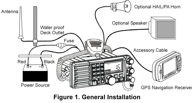
Connect the power cord and antenna to the radio. Antenna and Power Supply connections are as follows (see Figure 1):
1. Mount the antenna at least 3 feet away from the radio. At the rear of the radio, connect the antenna cable. It must have a PL259 connector. RG-8/U coaxial cable must be used if the antenna is 25 feet or more from the radio. RG58 cable can be used for distances less than 25 feet.
Figure 1. General Installation
GPS Navigation Receiver Accessory Cable
Optional Speaker Antenna
Fuse
Red
Power Source Black Water proof Deck Outlet
2. Connect the red power wire to a 13.8 VDC ±20% power source. Connect the black power wire to a negative ground.
3. If an optional remote extension speaker is to be used, refer to next section for connections.
4. It is advisable to have a Certified Marine Technician check the power output and the standing wave ratio of the antenna after installation.
8.3 ACCESSORY CABLE
White: External speaker (+)
Shield: External speaker (–)
Red: PA speaker (+)
Shield: PA speaker (–)
Blue: NMEA IN (+) from GPS navigation receiver
Green: NMEA IN (–) from GPS navigation receiver
Gray: NMEA OUT (+) to GPS navigation receiver
Brown: NMEA OUT (–) to GPS navigation receiver
When connecting the external speaker or GPS navigation receiver, strip off about 1 inch (2.5 cm) of the specified wire’s insulation, then splice the ends together using proper waterproofing techniques.
Wire Color/Description WHITE - External Speaker (+) SHIELD - External Speaker (–) RED - PA Speaker (+)
SHIELD - PA Speaker (–) BLUE- NMEA Input (+) GREEN - NMEA Input (–) GRAY- NMEA Output (+) BROWN-NMEA Output (–)
Connection Examples
Connect to external 4 Ohm audio speaker Connect to external 4 Ohm audio speaker Connect to external 4 Ohm PA speaker Connect to external 4 Ohm PA speaker Connect to NMEA (+) output of GPS Connect to NMEA (–) output of GPS Connect to NMEA (+) input of GPS Connect to NMEA (–) input of GPS
External Speaker GPS Receiver PA Speaker
Green
8.4 CONNECTION OF GPS WITH NMEA OUTPUT
• The GPS must have the NMEA Output turned on and set to 4800 Baud in the setup menu. If there is a selection for parity select none.
• For further information on interfacing /setting up your GPS. Please contact the manufacturer of the GPS receiver.
• GX3500S can read NMEA-0183 version 2.0 or higher. • The NMEA supported sentences are:
Input: GLL, GGA, RMC and GNS (RMC sentence is recommended) Output: DSC and DSE
(DSC sentences to Standard Horizon Plotter for Position Polling) If you have further inquires, please feel free to contact Product Support at:
Phone: (800) 767-2450
Email: [email protected]
8.5 CHECKING GPS CONNECTIONS
After connections have been made between the GX3500S and the GPS, a small satellite icon will appear on the top right corner of
the LCD display. To see additional GPS information, press the [F] key momentarily, then press the [6(NAV)] key. The GX3500S shows the Date, Time, SOG and COG.
Manufacturer/Model
Lowrance Portable
Magellan Fixed Mount
Magellan Portable
Northstar
Raytheon 420
Raytheon 520 / 620
Raytheon RL SERIES
Simrad
Sitex Neptune, Nautilus
Wires Orange Black (GND) Gray Black (GND) Orange Black (GND) Yellow Black (GND) Yellow Brown Blue Brown White Brown White Brown Gray Brown GX3500S Blue Green Blue Green Blue Green Blue Green Blue Green Blue Green Blue Green Blue Green Blue Green Wires Green Blue Brown White Blue White Black Blue Black (GND) Brown Black (GND) Yellow Green Green Black White Black White Black (GND) Manufacturer/Model STANDARD HORIZON
Furuno GP30, 36
Furuno GP1650, 1850
Garmin Fixed Mounts
Garmin Portables
JRC GPS500
JRC 100 SERIES
JRC 200 SERIES
Lowrance Fixed Mount
8.6 CHANGING THE GPS TIME
From the Factory the GX3500S shows GPS satellite time or UTC time. A time offset is needed to show the local time in your area.
1. Press and hold down the [CALL(MENU)] key until “Radio Setup” menu appears.
2. Press the [ENT] key, then select “Time Set” with the
CHANNEL selector knob. 3. Press the [ENT] key.
4. Turn the CHANNEL selector knob to select time set from UTC. See illustration below to find your off-set time from UTC. If “0:00” is assigned, the time is the same as UTC (Universal Time Coordinated or GMT Greenwich Mean Time).
5. Press the [ENT] key to store the time offset.
6. Press the [16/9] key or turn the CHANNEL selector knob to select “Exit,” then press the [ENT] key to return to the “Radio Setup” menu, select “Exit” and press the [ENT] key to return to radio operation.
8.7 CHANGING THE TIME LOCATION
You may select the time display between local time and UTC (time GPS sends to radio). Time is displayed when GPS position (LAT/LON) is displayed by press-ing the [F] key followed by the [6(NAV)] key.
1. Press and hold down the [CALL(MENU)] key until “Radio Setup” menu appears.
2. Press the [ENT] key, then select “Time Disp” in the “Radio Setup” menu with the CHANNEL selector knob.
3. Press the [ENT] key.
4. Turn the CHANNEL selector knob to select “UTC” or “Local.”
5. Press the [ENT] key to store the selected setting. 6. To exit this menu and return to radio operation mode
press the [16/9] key.
In the local time mode, the display shows the time by the 12-hour system. Meanwhile, the display shows the time by the 24-hour system in the UTC mode.
8.8 CHANGING COG TO TRUE OR MAGNETIC
Allows customizing the NAV data showing GPS Course Over Ground (COG). Factory default is True however following the steps below the COG can be changed to Magnetic.
1. Press and hold down the [CALL(MENU)] key until “Radio Setup” menu appears.
2. Press the [ENT] key, then select “Magnetic” with the
CHANNEL selector knob. 3. Press the [ENT] key.
4. Turn the CHANNEL selector knob to select “On” (rep-resenting “Magnetic”) or “Off” (representing “True”). 5. Press the [ENT] key to store the selected setting. 6. Turn the CHANNEL selector knob to select “Exit,”
8.9 OPTIONAL MMB-84 FLUSH MOUNT INSTALLATION
1. To assist in flush mounting, a template has been included. Use thistem-plate to find the mounting location.
2. Use the template to mark the location where the rectangular hole is to be cut. Confirm the space behind the dash or panel is deep enough to accom-modate the transceiver (at least 6 inches or 15 cm deep).
There should be at least 1/2 inch (1.3 cm) between the transceiver’s heatsink and any wiring, cables or structures.
3. Cut out the rectangular hole and insert the transceiver.
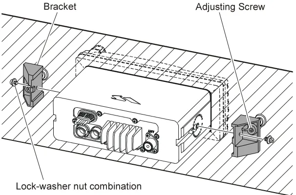
4. Fasten the brackets to the sides of the transceiver with the lock washer nut combination; so that the mounting screw base faces the mounting surface (see Figure 2).
5. Turn the adjusting screw to adjust the tension so that the transceiver is tight against the mounting surface.
Figure 2. MMB-84 Flush Mount Installation
Bracket Adjusting Screw
8.10
OPTIONAL ENHANCED RAM+ SECOND STATION MIC INSTALLATION
The GX3500S is capable of using up to 2 Enhanced RAM+ mics to remotely control the Radio, DSC and PA/Fog functions. In addition the GX3500S can operate as a full function intercom system. With 2 RAM+ mics connected theGX3500S or RAM+ mics can selective call each station individually or all at one time.
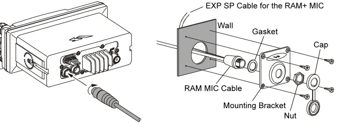
1. Connect the RAM+ MIC Cable to the RAM MIC CONNECTOR on the rear panel, then tighten the Cable Nut (See Figure 3).
2. Referring to Figure 3, make a 1.2” (30 mm) hole in the wall, then insert the RAM+ MIC Cable into this hole. Connect the Gasket and Mount Base to the RAM+ MIC Cable Connector using the Nut.
3. Drill the four Screw holes (approx. 2 mm) on the wall, then install the Mounting Base to the wall using four screws.
4. Put the Rubber Cap on to the Nut. The installation is now complete. 5. Wires for a external speaker are provided on the RAM+ mic cable. Connect
any 8 Ohm external speaker. When connected the RAM+ controls the vol-ume level of this speaker.
RAM+ or External Speaker Selection
By default the RAM+ internal speaker is turned on, however using the RAM+ mic this speaker can be turned off so the external speaker can be used. 1. Press and hold the [CALL/SET] key on the RAM+ Mic.
2. Using the [] or [] keys to select “RAM SPK” and press the [CALL/SET] key. 3. Press the [] or [] key to turn the RAM+
Speaker “oF.”
4. Press the [16/9] key to exit this mode.
Figure 3. Enhanced RAM+ MIC Installation Wall
Gasket
Mounting Bracket RAM MIC Cable
Cap
9 CONTROLS AND INDICATORS
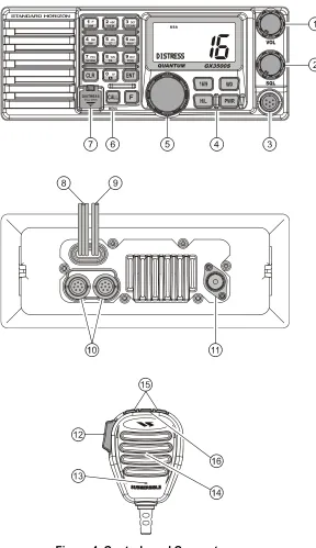
NOTE
This section defines each control of the transceiver. See Figure 4 for location of controls. For detailed operating instructions refer to section “10 BASIC OPERATION.”
VOLUME CONTROL (VOL)
Adjusting this control clockwise, increases the audio volume level.
SQUELCH CONTROL (SQL)
Adjusting this control clockwise, sets the point at which random noise on the channel does not activate the audio circuits but a received signal does. This point is called the squelch threshold. Further adjustment of the squelch control will degrade reception of wanted transmissions.
MICROPHONE CONNECTOR
Connect the supplied MH-63A6 Hand Microphone to this jack.
KEY BUTTON
[16/9] Key
Immediately recalls channel 16 from any channel location. Holding down this key recalls channel 9. Pressing the [16/9] key again reverts to the previous selected working channel.
Secondary use
Press and hold the [16/9] key then press the [WX] key to switch the Channel Group.
[WX] Key
Immediately recalls the previously selected NOAA weather channel from any channel.
Secondary use
Holding down the [16/9] key while pressing the [WX] key changes the Channel Group.
[H/L] Key
Figure 4. Controls and Connectors
DISTRESS
PULL OPEN
-/*
[PWR] Key
Turns the transceiver on and off. To turn the transceiver on, press and hold this key until the LCD turns on. To turn it off, press and hold this key until the LCD turns off. When the power is turned on, the transceiver is set to the last selected channel.
CHANNEL SELECTOR KNOB
Rotary knob used to select channels and to choose menu items (such as the DSC menu, radio setup menu, and DSC setup menu). The [UP()] / [DOWN()] keys on the microphone can also be used to select channels and menu items.
When the PA/FOG mode is activated, the CHANNEL selector knob adjust the audio output level.
Secondary Use (Depends on the transceiver version)
While holding down the [SCAN] key and turning the CHANNEL selector knob, you can confirm memory channels for scanning.
KEYPAD
[1(DIM)] Key
When in radio mode, this key is used to directly select channel digit “1” in a channel number.
Secondary use
Press the [F] key first then press the [1(DIM)] key, access the LCD Dim-mer menu. Refer to section “10.15 LCD DIMMER” for details.
[2(MEM)] Key
When in radio mode, this key is used to directly select channel digit “2” in a channel number.
Secondary use (Depends on the transceiver version)
Press the [F] key first then press the [2(MEM)] key, memorize the se-lected channel into the transceiver scan memory for scanning. When repeat the same procedures ([F] [2(MEM)]), DELETES the channel from the scan memory. Refer to section “10.12 SCANNING” for details. [3(SCAN)] Key
When in radio mode, this key is used to directly select channel digit “3” in a channel number.
Secondary use (Depends on the transceiver version)
[4(DW)] Key
When in radio mode, this key is used to directly select channel digit “4” in a channel number.
Secondary use (Depends on the transceiver version)
Press the [F] key first then press the [4(DW)] key, scan for voice commu-nications on the priority channel and another selected channel until a signal is received on either channel (Dual Watch). Refer to section “10.11 DUAL WATCH (TO PRIORITY CHANNEL)” for details.
[5(IC)] Key
When in radio mode, this key is used to directly select channel digit “5” in a channel number.
Secondary use
Press the [F] key first then press the [5(IC)] key, when the optional RAM+ Mic is connected, intercom operation will operate between radio and RAM+ Mic. Refer to section “10.16 INTERCOM OPERATION” for details. [6(NAV)] Key
When in radio mode, this key is used to directly select channel digit “6” in a channel number.
Secondary use
Press the [F] key first then press the [6(NAV)] key, the LCD displays NAV GPS Data, Time, SOG (Speed Over Ground), and COG (Course Over Ground) when a GPS is connected to the accessory cable of the
GX3500S. See section “8.4 CONNECTION OF GPS WITH NMEA OUT-PUT” for details.
[7(SCRM)] Key
When in radio mode, this key is used to directly select channel digit “7” in a channel number.
Secondary use
Press the [F] key first then press the [7(SCRM)] key, when the optional
CVS2500 Voice Scrambler Unit is installed, available to operate the Voice Scrambler function. Refer to section “10.17 VOICE SCRAMBLER” for details.
[8(PA)] Key
When in radio mode, this key is used to directly select channel digit “8” in a channel number.
Secondary use
[9(FOG)] Key
When in radio mode, this key is used to directly select channel digit “9” in a channel number.
Secondary use
Press the [F] key first then press the [9(FOG)] key, available to operate the Fog Horn function. Refer to section “10.13 PA/FOG OPERATION” for details.
[0] Key
When in radio mode, this key is used to directly select channel digit “0” in a channel number.
[CLR] Key
Press the [CLR] Key to cancel the menu selection and/or keypad entry. [ENT] Key
Press the [ENT] Key to determine the menu selection and/or keypad entry.
[CALL(MENU)] Key
Press the [CALL(MENU)] key to access the DSC OPERATION menu. The “INDIVIDUAL CALL,” “GROUP CALL,” and “ALL SHIPS CALL” func-tions can be accessed from the DSC OPERATION menu.
Secondary use
Press and hold the [CALL(MENU)] key to access the “Radio Setup” (refer to section “12 RADIO SETUP”) or “DSC Setup” menu (refer to section “11 DIGITAL SELECTIVE CALLING”).
[F] Key
Press the [F] key to activate the “Alternate” key function. [DISTRESS] Key
Used to send a DSC Distress Call. To send the distress call refer to section “11.3.1 (Transmitting A DSC Distress Call).”
ACCESSORY CONNECTION CABLE
Connects the GX3500S to a GPS, a PA speaker, and an external speaker.
DC INPUT CABLE
Connects the radio to a DC power supply capable of delivering 12V DC.
RAM+ MIC CONNECTORS
Connects the GX3500S to the enhanced RAM+ MIC (Remote Access Mi-crophone). Refer to section “13 ENHANCED RAM+ MIC OPERATION” for details.
ANTENNA JACK
Connects an antenna to the transceiver. Use a marine VHF antenna with an impedance of 50 ohms.
PTT (Push-To-Talk) SWITCH
Keys the transmitter when the transceiver is in radio mode. If the transceiver is in the intercom operation mode (between the RAM+ and the GX3500S), or PA mode, it activates the GX3500S microphone for voice communica-tions.
MICROPHONE
Transmits the voice message with reduction of background noise, using Clear Voice Noise Reduction Technology.
MICROPHONE SPEAKER
The audio heard through internal radio speaker is heard through micro-phone speaker.
[UP()] / [DOWN()] KEYS
The [UP()] and [DOWN()] on the microphone function the same as the
CHANNEL selector knob on the front panel of the transceiver. [16/9] Key
10 BASIC OPERATION
10.1 RECEPTION
1. After the transceiver has been installed, ensure that the power supply and antenna are properly connected.
2. Press and hold the [PWR] key until the radio turns on.
3. Turn the SQL knob fully counterclockwise. This state is known as “squelch off”. 4. Turn up the VOL knob until noise or audio from the speaker is at a
comfort-able level.
5. Turn the SQL knob clockwise until the random noise disappears. This state is known as the “squelch threshold.”
6. Turn the CHANNEL selector knob to select the desired channel. Refer to the channel chart on page 78 for available channels.
7. The keypad on the front may be used to directly select channels. Example to select channel 68:
1. Press [6(NAV)] 2. Press [8(PA)] 3. Press [ENT]
In the USA and Canadian modes, press and hold in the [0] key to select the “A” channel. Example to select channel 22A:
1. Press [2(MEM)] 2. Press [2(MEM)]
3. Press [0] until “A” appears to the right of the channel number 4. Press [ENT]
8. When a message is received, adjust the volume to the desired listening level. The “ ” indicator in the LCD is displayed indicating that the chan-nel is being used.
10.2 TRANSMISSION
1. Perform steps 1 through 6 of RECEPTION.
2. Before transmitting, monitor the channel to ensure it is clear.
THIS IS AN FCC REQUIREMENT!
3 Press the PTT (push-to-talk) switch. The “ ” indicator in the LCD is displayed.
4. Speak slowly and clearly into the microphone.
5. When the transmission is finished, release the PTT switch.
NOTE
10.3 TRANSMIT TIME - OUT TIMER (TOT)
When the PTT switch on the microphone is held down, transmit time is limited to 5 minutes. This limits unintentional transmissions due to a stuck microphone. About 10 seconds before automatic transmitter shutdown, a warning beep will be heard from the speaker(s). The transceiver will automatically go to receive mode, even if the PTT switch is continually held down. Before transmitting again, the PTT
switch must first be released and then pressed again.
10.4 SIMPLEX/DUPLEX CHANNEL USE
Refer to the VHF MARINE CHANNEL CHART (page 78) for instructions on use of simplex and duplex channels.
NOTE
All channels are factory-programmed in accordance with International, Industry Canada (Canada), and FCC (USA) regulations. Mode of opera-tion cannot be altered from simplex to duplex or vice-versa.
10.5 INTERNATIONAL, USA, AND CANADA MODE
1. To change the modes, hold the [16/9] key and press the [WX] key. The mode changes from International to Canadian to USA with each press of the [WX] key.
2. “INTL” will be displayed for International mode, and “CAN” will be displayed for Canadian mode, and “USA” will be displayed on the LCD for USA mode. 3. Refer to the VHF MARINE CHANNEL CHART (page 78) for allocated
chan-nels in each mode.
10.6 NOAA WEATHER CHANNELS
NOTE
NOAA Weather channels are available in the waters of USA and Canada only.
1. To receive a NOAA weather channel, press the [WX] key from any channel. The transceiver will go to the last selected weather channel.
2. Turn the CHANNEL selector knob on the radio or [UP()] / [DOWN()] keys on the microphone to select a different NOAA weather channel. 3. To exit from the NOAA weather channels, press the [WX] key. The
trans-ceiver returns to the channel it was on prior to a weather channel.
10.6.1 NOAA Weather Alert
section “12.9 WX ALERT”), the transceiver is capable of receiving this alert if the following is performed:
1. Program NOAA weather channels into the transceiver’s memory for scan-ning. Follow the same procedure as for regular channels under section “10.12.” 2. Press the [SCAN] key once to start memory scanning or hold down the
[SCAN] key during memory scanning to start priority scanning.
3. The programmed NOAA weather channels will be scanned along with the regular-programmed channels. However, scanning will not stop on a nor-mal weather broadcast unless a NOAA alert is received.
4. When an alert is received on a NOAA weather channel, scanning will stop and the transceiver will emit a loud beep to alert the user of a NOAA broadcast. 5. Press the [WX] key to stop the alert tone and receive the weather report.
NOTE
If the [WX] key is not pressed the alert tone will be emitted for 5 minutes and then the weather report will be received.
NOTE
The Weather Alert feature is also engaged while the transceiver is re-ceiving on one of the NOAA weather channels.
10.6.2 NOAA Weather Alert Testing
NOAA tests the alert system ever Wednesday between 11AM and 1PM. To test the QUANTUM’s NOAA Weather feature, on Wednesday between 11AM and 1PM, setup as in previous section and confirm the alert is heard.
10.7 EMERGENCY (CHANNEL 16 USE)
Channel 16 is known as the Hail and Distress Channel. An emergency is de-fined as a threat to life or property. In such instances, be sure the transceiver is on and set to CHANNEL 16. Then use the following procedure:
1. Press the microphone push-to-talk switch and say “Mayday, Mayday, May-day. This is , , ” (your vessel’s name).
2. Then repeat once: “Mayday, ” (your vessel’s name).
3. Now report your position in latitude/longitude, or by giving a true or mag-netic bearing (state which) to a well-known landmark such as a navigation aid or geographic feature such as an island or harbor entry.
4. Explain the nature of your distress (sinking, collision, aground, fire, heart attack, life-threatening injury, etc.).
8. Give your vessel’s description: length, design (power or sail), color and other distinguishing marks. The total transmission should not exceed 1 minute.
9. End the message by saying “OVER.” Release the microphone button and listen.
10. If there is no answer, repeat the above procedure. If there is still no re-sponse, try another channel.
10.8 CALLING ANOTHER VESSEL (CHANNEL 16 OR 9)
Channel 16 may be used for initial contact (hailing) with another vessel. However, its most important use is for emergency messages. This channel must be monitored at all times except when actually using another channel. It is monitored by the U.S. and Canadian Coast Guards and by other vessels.Use of channel 16 for hailing must be limited to initial contact only. Calling should not exceed 30 seconds, but may be repeated 3 times at 2-minute inter-vals. In areas of heavy radio traffic, congestion on channel 16 resulting from its use as a hailing channel can be reduced significantly in U.S. waters by using
channel 9 as the initial contact (hailing) channel for non-emergency communi-cations. Here, also, calling time should not exceed 30 seconds but may be repeated 3 times at 2-minute intervals.
Prior to making contact with another vessel, refer to the channel charts in this manual, and select an appropriate channel for communications after initial con-tact. For example, Channels 68 and 69 are some of the channels available to non-commercial (recreational) boaters. Monitor your desired channel in advance to make sure you will not be interrupting other traffic, and then go back to either channel 16 or 9 for your initial contact.
When the hailing channel (16 or 9) is clear, state the name of the other vessel you wish to call and then “this is” followed by the name of your vessel and your Station License (Call Sign). When the other vessel returns your call, immedi-ately request another channel by saying “go to,” the number of the other chan-nel, and “over.” Then switch to the new channel. When the new channel is not busy, call the other vessel.
After a transmission, say “over,” and release the microphone’s push-to-talk (PTT) switch. When all communication with the other vessel is completed, end the last transmission by stating your Call Sign and the word “out.” Note that it is not necessary to state your Call Sign with each transmission, only at the begin-ning and end of the contact.
10.9 MAKING TELEPHONE CALLS
To make a radiotelephone call, use a channel designated for this purpose, The fastest way to learn which channels are used for radiotelephone traffic is to ask at a local marina. Channels available for such traffic are designated Public Correspondence channels on the channel charts in this manual. Some ex-amples for USA use are Channels 24, 25, 26, 27, 28, 84, 85, 86, and 87. Call the marine operator and identify yourself by your vessel’s name, The marine operator will then ask you how you will pay for the call (telephone credit card, collect, etc.) and then link your radio transmission to the telephone lines. The marine telephone company managing the VHF channel you are using may charge a link-up fee in addition to the cost of the call.
10.10 OPERATING ON CHANNELS 13 AND 67
Channel 13 is used at docks and bridges and by vessels maneuvering in port. Messages on this channel must concern navigation only, such as meeting and passing in restricted waters.
Channel 67 is used for navigational traffic between vessels.
By regulation, power is normally limited to 1 Watt on these channels. Your radio is programmed to automatically reduce power to this limit on these channels. However, in certain situations it may be necessary to temporarily use a higher power. See page 18 ([H/L] key) for means to temporarily override the low-power limit on these two channels.
10.11 DUAL WATCH (TO PRIORITY CHANNEL)
Dual watch allows the radio to monitor one channel and the assigned Priority channel. By default the priority channel is set to 16, however the priority chan-nel may be changed by referring to section 12.5 Priority Chanchan-nel set.
1. Adjust the SQL knob until the background noise disappears. 2. Select the channel you wish to dual watch to “Priority channel.” 3. Press the [F] key followed by the [4(DW)] key.
The display will scan between Priority channel and the channel that was selected in step 2.
If a transmission is received on the channel selected in step 2, the GX3500S will dual watch between the working channel and the Priority channel.
10.12 SCANNING
Allows the user to select the scan type from Memory scan or Priority scan. “Memory scan” scans the channels that were programmed into memory. “Pri-ority scan” scans the channels programmed in memory with the pri“Pri-ority chan-nel.
10.12.1 Selecting the Scan Type
1. Press and hold down the [CALL(MENU)] key until “Radio Setup” menu appears.
2. Press the [ENT] key, then select “SCAN Type” in the “Radio Setup” menu with the CHANNEL selector knob.
3. Press the [ENT] key.
4. Turn the CHANNEL selector knob to select “ Prior-ity” or “Memory.”
5. Press the [ENT] key to store the selected setting. 6. To exit this menu and return to radio operation mode
press the [16/9] key.
10.12.2 Memory Scanning (M-SCAN)
1. Adjust the SQL knob until background noise disappears. 2. Select a desired channel to be scanned using the
CHANNEL selector knob. Press the [F] key followed by the [2(MEM)] key, “MEM” will appear on the LCD which indicates the channel has been programmed into the transceivers memory.
3. Repeat step 2 for all the desired channels to be scanned.
4. To DELETE a channel from the transceiver’s memory, select the channel then press the [F] key followed by the [2(MEM)] key, “MEM” will disappear in the LCD.
5. To start scanning, press the [F] key followed by the [3(SCAN)] key.
“M-SCAN” appears on the LCD. Scanning will pro-ceed from the lowest to the highest programmed
channel number and will stop on a channel when a transmission is received. 6. The channel number will blink during reception.
10.12.3 Priority Scanning (P-SCAN)
In the default setting, Channel 16 is set as the priority channel. You may change the priority channel to the desired channel from the Channel 16 by the Radio Setup Mode, refer to section “12.5 PRIORITY CHANNEL SET.”
1. Adjust the SQL knob until background noise disappears. 2. Select a desired channel to be scanned using the
CHANNEL selector knob. Press the [F] key followed by the [2(MEM)] key, “MEM” will appear on the LCD which indicates the channel has been programmed into the transceivers memory.
3. Repeat step 2 for all the desired channels to be scanned.
4. To DELETE a channel from the transceiver’s memory, select the channel then press the [F] key followed by the [2(MEM)] key, “MEM” will disappear in the LCD.
5. To start priority scanning, press the [F] key followed by the [3(SCAN)] key. “P-SCAN” appears on the LCD. Scanning will proceed between the memorized nels and the priority channel. CH 16 the priority chan-nel will be scanned after each programmed chanchan-nel.
6. To stop scanning, press the [16/9], [WX], [CALL(MENU)], or PTT key. You may change the scan resume time by the Radio Setup Mode, refer to section “12.7 SCAN RESUME TIME.”
10.13 PA/FOG OPERATION
PA/FOG mode allows the transceiver to be used as a 30W hailer when an optional STANDARD HORIZON 220SW or 240SW HAIL/PA Horn is installed. When in Hail mode the HAIL/PA Listen’s Back (acts as a microphone and sends sound to the front panel speaker) through the HAIL/PA speaker which provides two-way communications through the HAIL/PA speaker.
NOTE
When in PA or FOG mode the GX3500S will receive the last selected VHF channel before entering into the PA or FOG mode and receive DSC calls.
PA HAIL mode: Allows the transceiver to be used as a power hailer when an optional STANDARD HORIZON 220SW or 240SW HAIL/PA Horn is installed. The Hail mode has a listen-back feature which provides two way communication through the HAIL/PA speaker.
10.13.1 Operating the PA HAIL mode
1. Press the [F] key followed by the [8(PA)] key to acti-vate the PA HAIL mode.
2. Press the PTT switch to speak through the HAIL/PA speaker.
Rotate the CHANNEL selector knob to control the AF output level. The AF output level can be set from 0 to 30 watts.
3. To exit the PA HAIL mode and return to radio
opera-tion mode, press the [F] key followed by the [8(PA)] key again.
10.13.2 Operating the FOG HORN mode
Operator can select from Underway, Stop, Sail, Tow, Horn, Siren, Aground, or Anchor. Please refer to page 87 for FOG Horn Timing Chart.
1. Press the [F] key followed by the [9(FOG)] key, acti-vate the “FOG HORN” menu.
2. Turn the CHANNEL selector knob to select the one of the eight functions described above.
3. Press the [ENT] key.
4. On the “Horn” and “Siren” modes, press the PTT
switch to activate the tone through the HAIL/PA speaker.
Rotate the CHANNEL selector knob to control the AF output level. The AF output level can be set from 0 to 30 watts.
5. To exit the “FOG HORN” mode and return to radio operation mode, press the [F] key followed by the [9(FOG)] key again.
10.14 NAVIGATION INDICATION
The transceiver has the ability to display Date, Time, SOG, COG, as well as the position (LAT/LON), when connected to a GPS receiver.
1. Press the [F] key followed by the [6(NAV)] key, dis-play the position information on the LCD. If the GPS receiver is not receiving a fix, the display will be as shown in the illustration on the right.
10.15 LCD DIMMER
Allows setting up the backlight intensity or to turn it off. 1. Press the [F] key followed by the [1(DIM)] key to
en-abling the setting up the backlight intensity.
2. Turn the CHANNEL selector knob to select the de-sired backlight intensity. You will be able to see the effects of your changes.
3. When you have completed the adjustment, press the [F] key followed by the [1(DIM)] key again, return to radio operation mode.
10.16 INTERCOM OPERATION
If the RAM+ Mic is connected to the GX3500S, you may communicate between the GX3500S and RAM+ Mic, or RAM+ and RAM+ Mic (Refer to section “13.2 INTERCOM OPERATION”).
SCA NDW
NAV WX
CALL SET
M E M IC
U.I.C
M ENU
16 9
SCA NDW
NAV WX
CALL SET
M E M IC
U.I.C
M ENU
16 9
SCA NDW
NAV WX
CA LL SET
M EM IC
U.I.C
ME NU
16 9
SCA NDW
NAV WX
CA LL SET
M EM IC
U.I.C
ME NU
16 9
SCA NDW
NAV WX
CALL SET
M EM IC
U.I.C
ME N U
16 9
SCA NDW
NAV WX
CALL SET
M EM IC
U.I.C
ME N U
16 9 SCANDW NAV WX CA LL SET
M EM I C
U.I.C ME NU 16 9 SCANDW NAV WX CA LL SET
M EM I C
U.I.C ME NU 16 9 RAM 1 RAM 1 RAM 1 RAM 1
RAM 1 RAM 2
RAM 1 GX3500S
RAM 2 RAM 2
RAM 2 RAM 2
DISTRESSP ULL OPE N
-/ *
JKL
DISTRESSP ULL OPE N
-/ *
JKL
DISTRESSPU LL OPE N
-/ *
JK L
DISTRESSPU LL OPE N
-/ *
10.16.1 Communication
1. Press the [F] key followed by the [5(IC)] key, the mode is changed to “INTERCOM” mode.
2. If your GX3500S is equipped two RAM+ Mic’s, se-lect the companion you wish to communicate (RAM1,
RAM2, or ALL) with the CHANNEL selector knob, then press the [ENT] key. 3. When the “INTERCOM” operation is
activated, “Intercom” is displayed on the GX3500S, and “IC” is displayed on the RAM+ Mic.
4. Press the PTT switch. “Talk” will be shown on the display.
NOTE: A warning beep will be emitted when the GX3500S microphone’s PTT
switch is pressed while the RAM+ Mic’s
PTT switch is pressed.
5. Speak slowly and clearly into the microphone, hold the microphone about 1/2 inch away from your mouth.
6. When finished, release the PTT switch.
7. To exit the “INTERCOM” mode and return to radio operation mode, press the [F] key followed by the [5(IC)] key again.
10.16.2 Calling
Press and hold the [5(IC)] key for 1 second when the “INTERCOM” operation is activated, a calling beep is emitted twice from the transceiver speaker.
NOTE
When both RAM+ microphones are set to inter-com mode, the GX3500S will be temporarily dis-abled until the RAM+(s) exit the RAM+ to RAM+ intercom mode.
10.17 VOICE SCRAMBLER
If privacy of communications is desired, a CVS2500 voice scrambler (VS) can be installed in the transceiver. Contact your Dealer to have a CVS2500 installed. 1. Press the [F] key followed by the [7(SCRM)] key, the
voice scrambler is activated. “VS” will appear on the LCD.
2. Press the [F] key then press and hold the [7(SCRM)] key for 1 second, the “SCRM Code” will appear. 3. Turn the CHANNEL selector knob to change the
scrambler code. The scrambler code can be set from “0” to “3.”
4. Press the [ENT] key to save the scrambler code and return to radio opera-tion mode (with voice scrambler).
5. Monitor the channel before transmitting.
11 DIGITAL SELECTIVE CALLING
11.1 GENERAL
WARNING
This radio is designed to generate a digital maritime distress and safety call to facilitate search and rescue. To be effective as a safety device, this equipment must be used only within communication range of a shore-based VHF marine channel 70 distress and safety watch system. The range of signal may vary but under normal conditions should be approxi-mately 20 nautical miles.
NOTE
A DSC Warning sticker is included with the GX3500S. To comply with FCC regulations this sticker must be mounted in a location that can be eas-ily viewed from the location of the
GX3500S. Make sure the chosen lo-cation is clean and dry before apply-ing the sticker.
Digital Selective Calling is a semi-automated method of establishing a radio call, it has been designated by the International Maritime Organization (IMO) as an international standard for establishing VHF, MF and HF radio calls. It has also been designated as part of the Global Maritime Distress and Safety Sys-tem (GMDSS). It is planned that DSC will eventually replace aural watches on distress frequencies and will be used to announce routine and urgent maritime safety information broadcasts.
This new system allows mariners to instantly send a distress call with GPS posi-tion (when connected to the transceiver) to the Coast Guard and other vessels within range of the transmission. DSC will also allow mariners to initiate or receive Distress, Urgency, Safety, Routine, POSITION REQUEST, POSITION SEND, and Group calls to or from another vessel equipped with a DSC transceiver.
-/*
JK L
DI STR ES S
P ULL OPEN
11.2 MARITIME MOBILE SERVICE IDENTITY (MMSI)
11.2.1 What is an MMSI?
An MMSI is a nine digit number used on Marine Transceivers capable of using Digital Selective Calling (DSC). This number is used like a telephone number to selectively call other vessels.
THIS NUMBER MUST BE PROGRAMMED INTO THE RADIO TO OPERATE THE GX3500S DSC FUCTIONS.
How can I obtain an MMSI assignment?
Boat US offers online registration of a MMSI. Visit www.boatus.com/mmsi
11.2.2 Programming the MMSI
WARNING
User MMSI can be input only twice. If the user tries to input an MMSI more than twice, the radio will show the display on
the right. If the user needs to change the MMSI more than twice, the transceiver will have to be sent to Factory Service. Refer to the section “14.2. FACTORY SERVICE.”
1. Press and hold down the [CALL(MENU)] key until the “Radio Setup” menu appears.
2. Turn the CHANNEL selector knob to the left to se-lect “DSC Setup” menu.
3. Press the [ENT] key, then select “User MMSI” with the CHANNEL selector knob.
4. Press the [ENT] key. The “User MMSI” number will appear, and the first digit will be flashing.
5. Enter the your MMSI (up to nine digits) from the key-pad.
6. Press and hold the [ENT] key to store the number in memory.
11.3 DSC DISTRESS CALL
The GX3500S is capable of transmitting and receiving DSC Distress messages to all DSC radios. The GX3500S may be connected to a GPS to also transmit the Latitude, Longitude of the vessel.
11.3.1 Transmitting a DSC Distress Call
NOTE
To be able to transmit a DSC distress call an MMSI number must be programmed, refer to section “11.2.2 Programming the MMSI.”
In order for your ships location to be transmitted a GPS must be connected to the GX3500S, refer to section “8.4 CONNECTION OF GPS WITH NMEA OUT-PUT.”
1. Lift the red spring loaded DISTRESS cover and press the [DISTRESS] key. The “DISTRESS” menu will appear on the LCD.
2. Press and hold the [DISTRESS] key. The radios dis-play will count down (3-2-1) and then transmit the Distress call.
3. When the distress signal is sent, CH70 and “ ” icon will appear on the LCD. After the message has been sent, the radio will sound a Distress Alarm. 4. The transceiver will watch for a DSC
acknowledg-ment transmission on CH70 and also receive calls on CH16.
5. If an acknowledgement is received, select channel 16 and advise your distress situation.
6. If no acknowledgment is received, the distress call is repeated in 4 minute intervals until a DSC acknowl-edgment is received.
7. When a DSC Distress acknowledgment is received, a distress alarm sounds and channel 16 is automati-cally selected. The LCD shows the MMSI of the ship responding to your distress.
RECEIVED ACK: acknowledgment signal is received.
Transmitting a DSC Distress Call with Nature of Distress
The GX3500S is capable of transmitting a DSC Distress Call with the following “Nature of Distress” categories:
Undesignated, Fire, Flooding, Collision, Grounding, Capsizing, Sinking, Adrift, Abandoning, Piracy, MOB
1. Lift the red spring loaded DISTRESS cover and press the [DISTRESS] key. The “DISTRESS” menu will appear on the LCD.
2. Turn the CHANNEL selector knob to select the de-sired nature of distress category.
3. Press and hold the [DISTRESS] key. The radios dis-play will count down (3-2-1) and then transmit the Distress call.
4. When the distress signal is sent, CH70 and “ ” icon will appear on the LCD. After the message has been sent, the radio will sound a Distress Alarm. 5. The transceiver will watch for a DSC
acknowledg-ment transmission on CH70 and also receive calls on CH16.
6. If an acknowledgement is received, select channel 16 and advise your distress situation.
7. If no acknowledgment is received, the distress call is repeated in 4 minute intervals until a DSC acknowl-edgment is received.
8. When a DSC Distress acknowledgment is received, a distress alarm sounds and channel 16 is automati-cally selected. The LCD shows the MMSI of the ship responding to your distress.
RECEIVED ACK: acknowledgment signal is received.
RECEIVED RLY: relay signal is received from another vessel or coast station. 9. To cancel the DSC distress alarm signal from the speaker, press any key.
Cancel a DSC Distress Call
If a DSC Distress call was sent by error the GX3500S
allows you to send a message to other vessels to cancel the Distress Call that was made in error.
11.3.2 Receiving a DSC Distress Call
1. When a DSC Distress call is received, an emergency alarm sounds.
Then channel 16 is automatically selected. 2. Press any key to stop the alarm.
3. Turn the CHANNEL selector knob to change the dis-play to show the position of the vessel in distress. 4 If the position of the vessel distress data does not
include position, the LCD will show the display on the left.
NOTE
You must continue monitoring channel 16 as a coast station may require assistance in the rescue attempt.
11.4 ALL SHIPS CALL
The All Ships Call function allows contact to be established with other vessel stations without having their ID in the individual calling directory. Also, priority for the call can be designated as Urgency or Safety.
URGENCY Call: This type of call is used when a vessel may not truly be in distress, but have a potential problem that may lead to a dis-tress situation. This call is the same as saying PAN PAN PAN on channel 16.
11.4.1 Transmitting an All Ships Call
1. Press the [CALL(MENU)] key. The “DSC Operation” menu will appear.
2. Turn the CHANNEL selector knob to select “All Ships.” 3. Press the [ENT] key. (To cancel, turn the CHANNEL
selector knob to select “Exit.”)
4. Turn the CHANNEL selector knob to select the call
(“Urgency” or “Safety”).
5. Press the [ENT] key to transmit the selected type of all ships DSC call.
6. After the ALL SHIPS CALL is transmitted, the trans-ceiver will switch to CH16.
7. Listen to the channel to make sure it is not busy, then key the microphone and say PAN PAN PAN or “Securite, Securite, Securite” depending on the pri-ority of the call. Say your call sign and announce the channel you wish to switch to for communications.
11.4.2 Receiving an All Ships Call
1. When an all ships call is received, an emergency alarm sounds.
The radio will automatically change to channel 16. 2. Press any key to stop the alarm.
3. Turn the CHANNEL selector knob to see the MMSI of the vessel transmitting the All Ships Call.
11.5 INDIVIDUAL CALL
This feature allows the GX3500S to contact another vessel with a DSC VHF radio and automatically switch the receiving radio to a desired communications channel. This feature is similar to calling a vessel on CH16 and requesting to go to another channel (switching to the channel is private between the two stations).
11.5.1 Setting up the Individual / Position Call Directory
The GX3500S has a DSC directory that allows you to store a vessel or person’s name and the MMSI number associated with vessels you wish to transmit Indi-vidual calls, Position Requests and Position Send transmissions.
To transmit an Individual call you must program this directory with information of the persons you wish to call, similar to a cellular phones telephone directory. 1. Press and hold down the [CALL(MENU)] key until
“Radio Setup” menu appears.
2. Turn the CHANNEL selector knob to select “DSC
Setup” menu.
3. Press the [ENT] key, then select “INDIV DIR” with the
CHANNEL selector knob.
4. Press the [ENT] key, then select “Add” with the CHAN-NEL selector knob.
5. Press the [ENT] key.
6. Press the one of the Keypad keys to enter the first letter of the name of the vessel or person you want to reference in the directory.
Example: Press the [2(MEM)] key repeatedly to toggle among the seven available characters associated with that key: 2ABCabc.
If a mistake was made entering in the name, press-ing the [CLR] key to delete the wrong character. 7. Press the [ENT] key to store the first letter in the name
and step to the next letter to the right.
8. Repeat step 6 and 7 until the name is complete. The name can consist of up to eleven characters, if you
do not use all eleven characters press the [ENT] key to move to the next space. This method can also be used to enter a blank space in the name. To clear the previous letter, press the [CLR] key.
10. Enter the MMSI number by the keypad. If a mistake was made entering in the number, pressing the [CLR] key to delete the wrong character.
11. To store the data entered, press and hold the [ENT] key.
12. To enter another individual address, repeat steps 4 through 12.
13. To exit this menu and return to radio operation mode press the [16/9] key.
NOTE
Selecting “Next” or “Exit” will automatically save the name and MMSI number into memory.
11.5.2 Setting up Individual Reply
Allows setting up the radio to automatically (default setting) or manually re-spond to a DSC Individual call requesting you to switch to a working channel for voice communications. When Manual is selected the MMSI of the calling ves-sel is shown allowing you to see who is calling. This function is similar to caller id on a cellular phone.
1. Press and hold down the [CALL(MENU)] key until “Radio Setup” menu appears.
2. Turn the CHANNEL selector knob to select “DSC Setup” menu.
3. Press the [ENT] key, then select “INDIV Reply” with the CHANNEL selector knob.
4. Press the [ENT]key.
5. Turn the CHANNEL selector knob to select “Auto” or “Manual.”
6. Press the [ENT] key to store the selected setting. 7. To exit this menu and return to radio operation mode
11.5.3 Setting up the Individual/Group Call Ringer
When a Individual Call or Group Call is received the radio will produce a ringing tone for 3 minutes. This selection allows the Individual Call ringer time to be changed.
1. Press and hold down the [CALL(MENU)] key until
“Radio Setup” menu appear.
2. Turn the CHANNEL selector knob to select “DSC
Setup” menu.
3. Press the [ENT] key, then select “INDIV Ring” with the CHANNEL selector knob.
4. Press the [ENT] key.
5. Turn the CHANNEL selector knob to select ringing time of a Individual Call.
6. Press the [ENT] key to store the selected setting. 7. To exit this menu and return to radio operation mode
press the [16/9] key.
The GX3500S has the capability to turn off the Individual call ringer. 1. Press and hold down the [CALL(MENU)] key until
“Radio Setup” menu appear.
2. Turn the CHANNEL selector knob to select “DSC
Setup” menu.
3. Press the [ENT] key, then select “DSC Beep” with the
CHANNEL selector knob. 4. Press the [ENT] key.
5. Turn the CHANNEL selector knob to select “Individual” if you wish to disable the Individual Call ringer, or
“Group” if you wish to disable the Group Call ringer
and press the [ENT] key.
6. Turn the CHANNEL selector knob to select “Off.” 7. Press the [ENT] key to store the selected setting. 8. To exit this menu and return to radio operation mode
press the [16/9] key.
11.5.4 Transmitting an Individual Call
This feature allows the user to contact another vessel with a DSC radio. This feature is similar to calling a vessel on CH16 and requesting to go to another channel.
Pre-Programmable Calling
1. Press the [CALL(MENU)] key. The “DSC Operation” menu will appear.
2. Turn the CHANNEL selector knob to select “
Indi-vidual.” (To cancel, select “Exit” with the CHANNEL
selector knob or press the [16/9] key.)
3. Press the [ENT] key. The transceiver will beep, and the “Individual directory” will appear.
4. Turn the CHANNEL selector knob to select the “Indi-vidual” you want to contact.
5. Press the [ENT] key, then turn the CHANNEL selec-tor knob to select the operating channel you want to communicate on and press the [ENT] key.
6. Press the [ENT] key again to transmit the individual DSC signal.
7. After INDIVIDUAL CALL is transmitted, the trans-ceiver will wait 8 seconds for the acknowledgment. If the reply signal is not received, the transceiver will transmit again.
8. After the second INDIVIDUAL CALL is transmitted, if the reply signal is not received, the display will be as shown in the
illustra-tion on the right. To send the call again, press the [ENT] key.
9. When an individual call acknowledgment is received, the established channel is automatically changed to the channel which is selected on step 5 above and a ringing tone sounds.
Manual Calling
You may enter an MMSI number manually to contact without the Setting up the Individual Directory.
1. Press the [CALL(MENU)] key. The “DSC Operation” menu will appear.
2. Turn the CHANNEL selector knob to select “
Indi-vidual.” (To cancel, select “Exit” with the CHANNEL
selector knob or press the [16/9] key.)
3. Press the [ENT] key. The transceiver will beep, and the “Individual directory” will appear.
4. Turn the CHANNEL selector knob to select “Manual,” then press the [ENT] key.
5. Enter the MMSI number (nine digits) which you want to contact by the keypad, then press the [ENT] key. 6. Turn the CHANNEL selector knob to select “Manual,”
then press the [ENT] key.
7. Turn the CHANNEL selector knob to select the oper-ating channel which you want to use for communica-tion, then press the [ENT] key.
8. Press the [ENT] key again to transmit the individual DSC signal.
9. After INDIVIDUAL CALL is transmitted, the trans-ceiver will wait 8 seconds for the acknowledgment. If the reply signal is not received, the transceiver will transmit again.
10. After the second INDIVIDUAL CALL is transmitted, if the reply signal is not received, the display will be as shown in the illustration on the right. To send the call again, press the [ENT] key or to exit the mode, press the [CLR] key.
11. When an individual call acknowledgment is received, the established channel is automatically changed to the channel which is selected on step 5 above and a ringing tone sounds.
11.5.5 Receiving an Individual Call
When receiving an individual call, an acknowledgment must be sent back to the calling station. The GX3500S default setting is Automatic, but has a selection that allows you to manually send a reply before the radio will switch to the re-quested calling channel. This selection is useful if you want to see who is calling and requesting you to switch to a channel for communications, similar to caller id on a cellular phone.
1. When an individual call is received, an individual call ringing alarm sounds. The radio automatically switches to the requested
channel.
2. Press any key to stop the alarm.
3. Press the PTT on the mic and talk to the calling ship.
11.5.6 Setting Up the Call Waiting Function
Allows the GX3500S to be setup to reply (ABLE) or set the radio so it transmits a call that advises the calling vessel the person is UNABLE to reply to the call at this time. This function is similar to an answering machine. When set up in UNABLE and a individual call is received the Individual call from the other ves-sel is logged in the CALL WAITING directory for you to review and call back at a later time.
1. Press and hold down the [CALL(MENU)] key until “Radio Setup” menu appears.
2. Turn the CHANNEL selector knob to select “DSC Setup” menu.
3. Press the [ENT] key, then select “INDIV ACK” with the CHANNEL selector knob.
4. Press the [ENT] key.
5. Turn the CHANNEL selector knob to select “Able” or “Unable.”
6. Press the [ENT] key to store the selected setting. 7. To exit this menu and return to radio operation mode
11.6 GROUP CALL
This feature allows the user to contact a group of specific vessels (example members of a yacht club) using DSC radios with Group call function to auto-matically switch to a desired channel for voice communications.
11.6.1 Setting up a Group Call
For this function to operate the same Group MMSI must be programmed into all the DSC VHF radios within the group of vessels that will be using this fea-ture. The group MMSI is a 9 digit (first digit permanently set to “0”) that will allow other radios to call your vessel along with others to automatically switch to a working channel for voice communications. This function is very useful for yacht clubs and vessels traveling together that want to collectively make announce-ments on a predetermined channel.
1. Press and hold down the [CALL(MENU)] key until “Radio Setup” menu appears.
2. Turn the CHANNEL selector knob to select “DSC Setup” menu.
3. Press the [ENT] key, then select “Group DIR” with the CHANNEL selector knob.
4. Press the [ENT] key, then select “Add” with the
CHANNEL selector knob. 5. Press the [CALL(MENU)] key.
6. Press the one of the Keypad keys to enter the first letter of the name of the group you want to reference in the directory.
Example: Press the [2(MEM)] key repeatedly to toggle among the seven available characters associated with that key: 2ABCabc.
If a mistake was made entering in the name, press-ing the [CLR] key to delete the wrong character. 7. Press the [ENT] key to enter the desired letter and
move the cursor one space to the right.
8. Repeat step 6 and 7 until the name is complete. The name can consist of up to eleven characters, if you do not use all eleven
characters press the [ENT] key to move to the next space. This method can also be used to enter a blank space in the name. To clear the previous letter, press the [CLR] key.
number entry.
10. Enter the MMSI number by the keypad. If a mistake was made entering in the number, press the [CLR] key to delete the wrong character.
11. To enter the desired number and move one space to
the right press the [ENT] key. Repeat procedure until all nine spaces of MMSI number are entered.
12. If a mistake was made entering in the name or the MMSI number repeat pressing the [ENT] key until the wrong character is selected, then move the
CHANNEL selector knob to correct the entry.
13. To store the data entered, press and hold the [ENT] key. 14. To enter another individual address, repeat steps 4 through 13.
15. To exit this menu and return to radio operation mode press the [16/9] key.
11.6.2 Transmitting a Group Call
Pre-Programmable Calling
1. Press the [CALL(MENU)] key. The “DSC Operation” menu will appear.
2. Turn the CHANNEL selector knob to select “Group.” (To cancel, select “Exit” with the CHANNEL selector knob or press [16/9] key.)
3. Press the [ENT] key. The transceiver will beep, and the “Group Directory” will appear.
4. Turn the CHANNEL selector knob to select the “Group” you want to contact.
5. Press the [ENT] key, then turn the CHANNEL selec-tor knob to select the operating channel you want to communicate on and press the [ENT] key.
6. Press the [ENT] key again to transmit the Group Call signal.
7. After the GROUP CALL is transmitted, all the radios in the group will switch to the designated channel. 8. Listen to the channel to make sure it is not busy, then
Manual Calling
You may enter an MMSI number manually to contact without the Setting up the Group call number.
1. Press the [CALL(MENU)] key. The “DSC Operation” menu will appear.
2. Turn the CHANNEL selector knob to select “Group.” (To cancel, select “Exit” with the CHANNEL selector knob or press [16/9] key.)
3. Press the [ENT] key. The transceiver will beep, and the “Group Directory” will appear.
4. Turn the CHANNEL selector knob to select “Manual,” then press the [ENT] key.
5. Enter the MMSI number (eight digits) which you want to contact by the keypad, then press the [ENT] key. 6. Turn the CHANNEL selector knob to select “Manual,”
then press the [ENT] key.
7. Turn the CHANNEL selector knob to select the oper-ating channel which you want to communicate on, then press the [ENT] key.
8. Press the [ENT] key again to transmit the Group Call signal.
9. After the GROUP CALL is transmitted, all the radios in the group will switch to the designated channel. 10. Listen to the channel to make sure it is not busy, then
11.6.3 Receiving a Group Call
1. When a group call is received, the GX3500S will pro-duce a ringing alarm sound.
2. The radio automatically switches to the requested channel.
3. Press any key to stop the alarm.
4. Monitor the channel for the person calling the Group for a message.
5. If you want to respond, monitor the channel to make sure it is clear, then press the PTT on the mic and talk to the calling ship(s).
NOTE