ISSN: 2319-8753
International Journal of Innovative Research in Science, Engineering and TechnologyVol. 2, Issue 5, May 2013
Study of PID Controller Based Pitch Actuator
System for Variable Speed HAWT using
MATLAB
Vishal T. Makvana
1, Rinal K. Ahir
2, Dhaval K. Patel
2, Jitendra A. Jadhav
2 M.E. Energy Engineering 4th Sem, Government Engineering College, Valsad, Gujarat, India1Assistant Professor, Department of Electrical Engineering, Government Engineering College, Valsad, Gujarat, India2
Abstract: As the energy demand and greenhouse gases emission is increasing day by day the popularity of renewable energy systems is also being raised. One of the most popular renewable energy systems over the past decade has been the wind energy or wind turbines. Wind turbine extracts kinetic energy from the wind. Currently much research has concentrated on improving the aerodynamic performance of wind turbine. Variable speed horizontal axis wind turbines use blade pitch control to meet specified objectives for three regions of operation named low wind, medium wind and high wind conditions.
In this paper a control strategy is being developed for variable speed horizontal axis wind turbine which will allow the turbine to run at its maximum efficiency. For this purpose the PID controller based pitch actuator system is used to control the aerodynamic power of wind turbine. MATLAB Simulink power system tool is used to develop the model of PID controller. In this paper a model for the simulation of the PID controller based pitch actuator system is constructed using properly selected sub blocks. Step response of this PID controller based pitch actuator system will be analyzed. The above presented model can be a useful tool for wind power industry to study the behavior of wind turbines.
Keywords: Wind Energy Conversion System, Wind Energy Conversion System, Wind Turbine Characteristics, Pitch Actuator System Modelling
I. INTRODUCTION
Global warming is considered as one of the most serious problems facing the global community. Certain gases, such as carbon dioxide, when released in the atmosphere through the burning of fossil fuels, create a "greenhouse effect." Clean, renewable energy solutions, such as wind, solar, and hydroelectric systems, that do not rely on fossil fuels for energy generation help curb the effects of global warming. Although wind has been used as an energy source for centuries, only within the last 30 years have advances in technology allowed wind energy to become an increasingly important part of the nation‟s energy mix.
Currently, the Indian wind energy sector has an installed capacity of 17,365.03 MW (as on August 31, 2012). In terms of wind power installed capacity, India has the fifth largest capacity in the World. Wind power accounts for 6% of India's total installed power capacity, and it generates 1.6% of the country's power. Research to extract the maximum power out of wind energy is an essential part of making wind energy much more viable and attractive.
II. WINDENERGYCONVERSIONSYSTEM
By definition a wind turbine is a rotating device that converts the kinetic energy in wind into mechanical energy. Wind turbines can be classified into two types based by the axis in which the turbine rotates.
A. HORIZONTAL AXIS WIND TURBINE
Figure 1 HAWT and VAWT Source: American Wind Energy Association
B. VERTICAL AXIS WIND TURBINE
The vertical axis wind turbines have the axis of rotation vertical with respect to the ground (and roughly perpendicular to the wind stream). The structure of these wind turbines are such that they can capture wind irrespective of its direction, thus changes in wind direction have fewer negative effects on this type of turbine. It is of great benefit in places where the wind direction keeps varying. However, the overall efficiency of these turbines in producing electricity is lower than HAWTs. Unlike the HAWT where the gearbox and generator are placed on top of the tower, the generator and gearbox are generally placed near the ground. This makes it more accessible and easier for maintenance. But they do not come without any drawbacks. Some designs produce pulsating torque which results in fatigue. It is also difficult to mount vertical-axis turbines on towers. They are often installed nearer to the base on which they rest. As the wind speed is slower at a lower altitude, so less wind energy is available for a given size turbine.
III.WINDTURBINECHARACTERISTICS
A. CUT IN SPEED
At very low wind speeds, there is insufficient torque exerted by the wind on the turbine blades to make them rotate. However, as the speed increases, the wind turbine will begin to rotate and generate electrical power. The speed at which the turbine first starts to rotate and generate power is called the cut-in speed and is typically between 3 and 4 meters per second.
B. RATED OUTPUT WIND SPEED
As the wind speed rises above the cut-in speed, the level of electrical output power rises rapidly as shown in figure. However, typically somewhere between 12 and 17 meters per second, the power output reaches the limit that the electrical generator is capable of. This limit to the generator output is called the rated power output and the wind speed at which it is reached is called the rated output wind speed.
C. CUT OUT SPEED
As the speed increases above the rate output wind speed, the forces on the turbine structure continue to rise and, at some point, there is a risk of damage to the rotor. As a result, a braking system is employed to bring the rotor to a standstill. This is called the cut-out speed and is usually around 25 meters per second.
IV.PITCHCONTROLLEDWINDTURBINE
ISSN: 2319-8753
International Journal of Innovative Research in Science, Engineering and TechnologyVol. 2, Issue 5, May 2013
mechanism which quickly turns the rotor blades slightly out of the wind. On the other hand, the blades are turned back into the wind whenever the wind goes down again. Thus the rotor blades have to be able to twist around their longitudinal axis (to pitch). This results in variation of the force exerted by the wind on the rotor shaft. The pitch mechanism is usually operated using hydraulics. The advantages of this type of control are good power control, assisted startup and emergency stop.
The maximum rate of change of the pitch angle is in the order of 3 to 10 degrees/second. The Pitch angle controller has a slight over-speeding of the rotor above its nominal value can be allowed without causing problems for the wind turbine structure.Pitch actuators at the roots of the blades directly control the aerodynamic power input to the rotor.
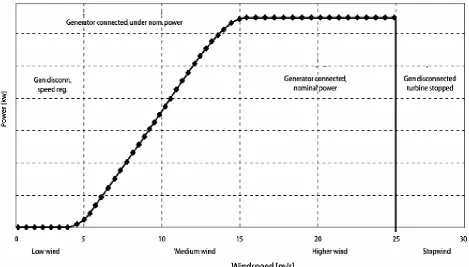
The momentary wind conditions can be divided into four categories, as shown by the power curve in Figure 2
I. Low wind, the generator is not connected to grid
II. Medium wind, the generator is connected, but does not produce nominal power III. Higher wind, the generator is connected and produces nominal power
IV. Stop wind, the generator is disconnected and the turbine is stopped
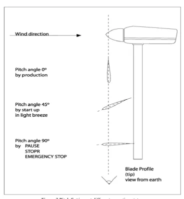
When the wind speed is very low and the rotor does not rotate or rotates with a very low speed, the pitch angle will be approximately 45o. This will provide a maximum start moment to the rotor, permitting a quicker start when the wind speed increases. The controller will then pitch the blades to 0o, that is, into the wind. The rotating speed for the rotor and the generator will increase towards the nominal level, which the controller will try and maintain with speed control. When the wind speed decreases and the produced power become negative, the generator will be disconnected from the grid and the controller will control the speed.
If the wind continues to decrease, the rotating speed will decrease below the nominal value and the rotor will run freely. At medium wind speed, the rotating speed is regulating to the nominal value, and if the pitch angle can be maintained at 5o, (or equivalently, there is enough energy in the wind) the generator is connected to the grid. When the generator is connected and there is sufficient energy in the wind to produce nominal power, the pitch angle is regulated as a function of the wind speed. This function, called OptiTip, is precisely calculated, simulated, and evaluated based on measurements. This function is implemented in turbines to optimize the aerodynamics of the blades, which will, in turn, optimize energy production.
Figure 3 Pitch Settings at different operating states
V. PITCHACTUATORSYSTEMMODELLING
For modeling of pitch actuator system three models have been developed in MATLAB. The three models are:
1. Proportional Control based Pitch Actuator System
2. Pitch Actuator System with constant value of pitching speed 3. PID Control based Pitch Actuator System
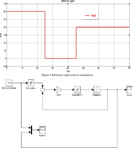
All these models are tested against a standard pitch angle input signal which is shown in figure 4 below:
A. PROPORTIONAL CONTROL BAESD PITCH ACTUATOR SYSTEM
ISSN: 2319-8753
International Journal of Innovative Research in Science, Engineering and TechnologyVol. 2, Issue 5, May 2013
Figure 4 Reference input used in simulations
Figure 5 Block diagram of proportional control based pitch actuator system
Figure 6 Pitch angle response when K = 0.1 Figure 7 Pitch angle response when K=0.5
Figure 8 Pitch angle response when K=1 Figure 9 Pitch angle response when K=5
ISSN: 2319-8753
International Journal of Innovative Research in Science, Engineering and TechnologyVol. 2, Issue 5, May 2013
In this model, the pitching speeds of the blades are to be kept constant. This way, the actuator system is not only simple but the stress on the blades is also considerably reduced. The main disadvantage of the first version actuator is that we cannot predict which pitch angle will be needed at that time when the actuator has reached command value. At this time the wind condition may have changed and then we will need another setting. The second version compares „on line‟ the proper criterion and then decides if to increase or decrease the pitch angle, without predicting the future angle like in the first version.
The Simulink model used has been shown in figure 10 above. An embedded model block has been used where it has been defined that:
If (error in pitch angle is positive)
then pitching speed = s (where “s” is a previously chosen value of speed)
If (error in pitch angle is negative)
then pitching speed = (-s)
Else pitching speed = 0
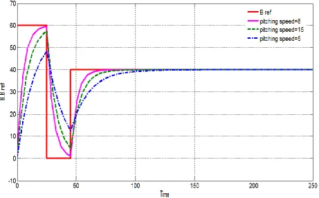
The response of this system has been observed for three different values of pitching speed viz. 5 deg./sec, 8 deg./sec, and 15 deg. /sec. The result of these tests has been shown in figure 11 below. It can be seen that if the pitching speed is set too low, it cannot effectively track the input signal causing an error to prevail at all times. Also a very high value of pitching speed demands a very high torque to be exerted on the blades which may lead to undesirable stresses on the blade and actuator.
Figure 11 Pitch angle response of Pitch Actuator System with constant pitching speed
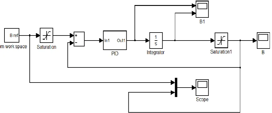
C. PID CONTROLLER BAESD PITCH ACTUATOR SYSTEM
Figure 12 Block diagram of PID controller based pitch actuator system
Figure 13 Pitch angle response of PID controller Figure 14 Pitch angle response of PID controller when Kp=2, Ki=0.01 and Kd=0 when Kp=2, Ki=0.01 and Kd=2
ISSN: 2319-8753
International Journal of Innovative Research in Science, Engineering and TechnologyVol. 2, Issue 5, May 2013
The response of this system has been observed for different values of proportional gain Kp, integral gain Ki and
derivative gain Kd and shown in figure 13, 14, 15 and 16 above
As can be seen, the system produces a decent response in the first case where the gains are Kp=2, Ki=0.01 and Kd=0.
The general approach is that the values of gains, once set, are not changed.
VI.CONCLUSION
A complete model for the study of PID controller based pitch actuator system for variable speed horizontal axis wind turbine is developed using MATLAB-Simulink. A variety of component blocks have been used from various simulink libraries and also from other compatible tool boxes such as power system blocksets, control system toolbox etc. The user can easily select or modify the step sizes, tolerances, simulation periods, output options, etc. with the help of appropriate menu from within simulink blocks. Any parameter within any block or subsystem of the model can be easily modified. The values of time response parameters of the pitch actuator system are observed and the fine tuning of the controller parameters is performed. For PID control based pitch actuator system when the values of Kp, Ki and Kd
is taken as 2,0.01 and 2 it gives decent response. It can be seen that if the pitching speed is set too low, it cannot effectively track the input signal causing an error to prevail at all times. Also a very high value of pitching speed demands a very high torque to be exerted on the blades which may lead to undesirable stresses on the blade and actuator.
REFERENCES
[1] Atul Sharma, Jaya Srivastava, Sanjay Kumar Kar and Anil Kumar, “Wind energy status in India: A short review,” Renewable and Sustainable
Energy Reviews, December 2011, pp. 1157– 1164.
[2] World Wind Energy Association. World Wind Energy Report 2012, WWEA, Bonn, Germany, June, 2012.
[3] India Wind Energy Outlook 2012, published by Global Wind Energy Council (GWEC) at “Wind Power India 2012” being organized on
November 2012 in Chennai.
[4] Indian Wind Energy Association, http://www.inwea.org/
[5] V. K. Gaudani, “Energy Audit and Energy Management,” Vol. 1, 1st Edn, IECC Press, 2009.
[6] Godswill Ofualagba, Emmanuel Ubeku, “The Modeling and Dynamic Characteristics of a Variable Speed Wind Turbine,” Journal of Energy
Technology and Policy, Vol. 1, No.3, 2011, ISSN 2224-3232.
[7] V. Ramakrishnan and S. K. Srivasta, “Pitch Control of Wind Turbine Generator by using New Mechanism” J. Electrical Systems.
[8] H. Polinder, D. Bang, R. P. J. O. M. van Rooij, A. S. McDonald, M. A. Mueller, “10-MW Wind Turbine Direct-Drive Generator Design with
Pitch or Active Speed Stall Control,” IEEE, 2007, pp.1390-1395.
[9] E. Muljadi and C. P. Butterfield, “Pitch-Controlled Variable-Speed Wind Turbine Generation,” IEEE Transactions on Industry Applications,
Vol. 37, No. 1, January/February 2001, pp. 240-246.
[10] Chatinderpal Singh, “Variable Speed Wind Turbine,” International Journal of Engineering Science & Advanced Technology Volume-2,