Design and Structural Analysis of Ceramic
Coated Petrol Engine Piston Using Finite
Element Method
Vinod Kumar Yadav
1, Yogesh Mishra
2P.G. Student, Department of Mechanical Engg., NRI Institute of Information science and tech., Bhopal, M.P, India1 Professor, Department of Mechanical Engg. ,NRI Institute of Information science and technology, Bhopal, M.P, India2
ABSTRACT: Piston is made of aluminium alloys is a crucial part in internal combustion engine. When the combustion of fuel take place insides the engine cylinder, high pressure and high temperature will be developed as the engine will operate at high load and at high speed. As a result of this high thermal and high structural stresses in the piston is produced inside the engine cylinder and if these stresses exceeds the designed values, the failure of piston take place. To avoid the failure of the piston thermal and structural intensity should be reduced to safe allowable limits. In this work an attempt is made to reduce the thermal and structural stress intensity by coated the piston with ceramic material. The zirconia-based ceramic coatings are used as thermal barrier coatings owing their low conductivity and their relatively high coefficient of thermal expansion. Firstly the structural and thermal stresses analyses are investigated on a conventional (uncoated) piston made of aluminium alloy namely A2618. Secondly the structural and thermal analyses are performed on the piston coated with zirconium material using the ANSYS software. The effects of coating on the thermal behaviours of the piston are investigated. The main objective is to investigate and analyse the structural and thermal stress distribution of the piston at the real engine condition during combustion process. The analysis is carried out to reduce the stress concentration on the upper end of the piston .i.e. piston head/crown and piston skirt and sleeve using ANSYS software. The result obtained is compared to select the better material for piston manufacturing.
KEYWORDS: Engine piston, thermal analysis, structural analysis, FE analysis.
I.INTRODUCTION
expanding gas in the cylinder to the crankshaft via a piston rod and connecting rod. In a pump, the function is reversed and force is transferred from the crankshaft to piston for the purpose of compressing or ejecting the fluid in the cylinder.
Fig.1 showing assembly of Piston
1.1 RESEARCH OBJECT-PISTON
Engine piston is most complex part compared to other components in an automobile sector. Still lots of research work have been conducting on piston regarding material composition, geometry and manufacturing technique. The function of the internal combustion engine piston is to receive the energy from expanding gasses after during combustion and transmit it to the crankshaft by means of connecting rod. Piston expands appreciably when it gets heated during the operation so actual clearances need to be given otherwise it will lead to engine seize. And hence to avoid this case pistons are made up of cast aluminium alloy matrix with the combination of reinforcement in different weight percentage. For the better result here replace the conventional piston material (uncoated) with coated material. The zirconia-based ceramic coatings are used as thermal barrier coatings owing their low conductivity and their relatively high coefficient of thermal expansion. The addition of coating material to the aluminium matrix improves the tensile strength, compressive strength, hardness and thermal behaviours. The coated material is having more factor of safety compare to uncoated alloy material because of more yield strength at elevated temperature due to presence of the coating in the alloys.
Thermal Barrier Coatings in petrol engines lead to advantages including higher power density, fuel efficiency, and multi fuel capacity due to higher combustion chamber temperature. Using thermal Barrier Coatings can increase engine power and decrease the specific fuel consumption and increase the exhaust gas temperature. Although several systems have been used as thermal barrier coatings for different purposes, zirconium has received the most attention. Several important factors playing an important roles in thermal barrier coatings lifetimes including thermal conductivity, thermal, chemical stability at the service temperature, high thermo- mechanical stability to the maximum service temperature and the thermal expansion coefficient.
Piston of the engine piston must possess the following characteristics:
Strength to resist gas pressure.
Strength to resist inertia forces.
Must have minimum weight.
Must be able to reciprocate with minimum noise.
Must have sufficient bearing area to prevent wear.
Must seal the gas from top and oil from the bottom.
Must have good resistance to distortion under heavy forces and high temperature.
The paper describes the materialistic optimization with using finite element analysis technique to predict the higher stress and critical region on the component. The optimization is carried out to reduce the stress concentration on the upper end of the piston i.e. (piston head/crown and piston skirt and sleeve). With using computer aided design (CAD), Unigraphic (UG NX-8) software the structural model of a piston will be developed. Furthermore, the finite element analysis performed with using ANSYS software
.
1.2CHARACTERIZATION OF MATERIAL
The material chosen for this work are A2618 as base material for a combustion engine piston. The relevant mechanical and thermal properties of A2618 aluminum alloys are listed in the below table 1. The zirconia-based ceramic coatings are used as thermal barrier coatings owing to their low conductivity and their relatively high coefficients of thermal expansion, which reduce the detrimental interfacial stresses. Material properties of the MgZrO3, NiCrAl and piston material made of A2618 alloy. Piston is coated with a 350 μm thickness of MgZrO3 over a 150 μm thickness of NiCrAl bond coat as shown below table 2
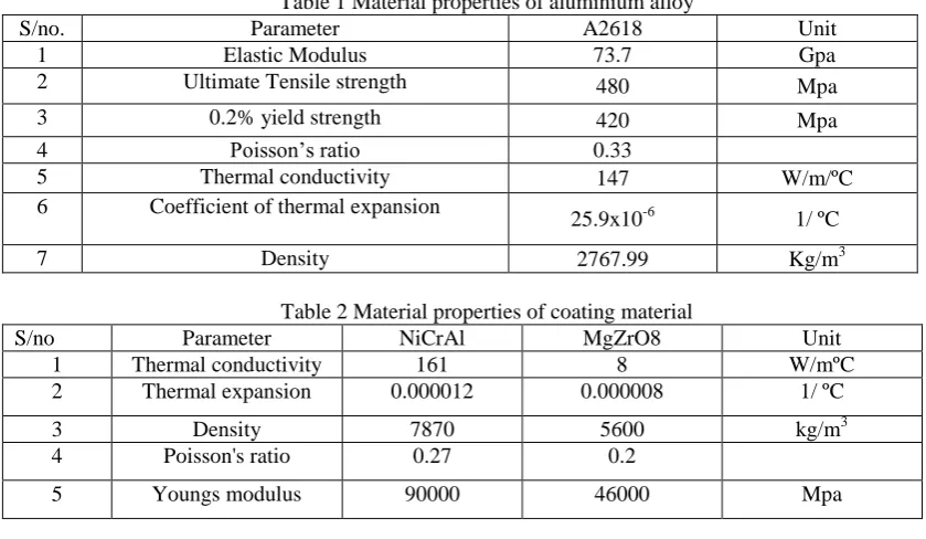
Table 1 Material properties of aluminium alloy
S/no. Parameter A2618 Unit 1 Elastic Modulus 73.7 Gpa 2 Ultimate Tensile strength 480 Mpa 3 0.2% yield strength 420 Mpa 4 Poisson’s ratio 0.33
5 Thermal conductivity 147 W/m/ºC 6 Coefficient of thermal expansion
25.9x10⁻⁶ 1/ ºC 7 Density 2767.99 Kg/m3
Table 2 Material properties of coating material
S/no Parameter NiCrAl MgZrO8 Unit 1 Thermal conductivity 161 8 W/mºC 2 Thermal expansion 0.000012 0.000008 1/ ºC 3 Density 7870 5600 kg/m3 4 Poisson's ratio 0.27 0.2
5 Youngs modulus 90000 46000 Mpa
1.3ENGINE SPECIFICATION
The Engine selected for this work is a single cylinder four stroke air cooled 100cc type Bajaj Kawasaki petrol engine. The main parameter shows in the table below table 3
Table 3Engine specification
Engine
Type 4-Stroke, air cooled, single cylinder
Number of cylinder Single cylinder
Bore 51mm
Compression ratio 8.4
Fuel consumption 87kmpl (under standard condition)
Performance Maximum power 6.03kw@ 7500 rpm Maximum torque 8.05 N-m@5500 rpm
Transmission
Clutch Wet multi disc type
Transmission 4-speed, constant mesh type Gear shift pattern All down foot shift
Dimensions
Overall length 1925mm Overall width 785mm Overall height 1030mm Wheel base 1215mm Ground clearance 150mm Kerb weight with full tank 109kg
Capacity Fuel tank 9.3 liters including 2.2 liter reserve
II.PROBLEMFORMULATION
The main objective is to investigate and analyse the structural and thermal stress distribution of the piston at the real engine condition during combustion process. The analysis is carried out to reduce the stress concentration on the upper end of the piston.i.e. piston head/crown and piston skirt and sleeve using ANSYS software. In this paper the material A2618 (uncoated piston) is replaced with coated piston. Analytical calculation is done to finalized the dimension and check the strength of piston. Piston model is created in UG-Nx8 using the calculated analytical dimension. Analysis of both the uncoated and coated piston is performed using the software namely ANSYS 13. After analysis comparisons is made between the uncoated piston and coated piston in terms of total deformation, equivalent stress, and total strain.
III.METHODOLOGY
Analytical design of piston using specification of Bajaj Kawasaki petrol engine.
Creation of 3D models of piston using UG-Nx8.
Meshing of 3D models using ANSYS 13.0.
Analysis of pistons using static stress analysis method.
Comparative performance of aluminium alloy pistons under static stress analysis method.
Analysis of pistons under thermal and mechanical loads i.e. the pistons are subjected to a uniform gas pressure and non-uniform temperature distribution.
Comparative performance of the aluminium alloy pistons (uncoated and coated) under thermal and mechanical loads i.e. the pistons are subjected to a uniform gas pressure and non-uniform temperature distribution.
3.1ANALYTICALDESIGN
ring (mm), h1 = width of top lands (mm) , h2 = width of ring lands (mm), t1 = thickness of piston barrel at the top end (mm), t2 = thickness of piston barrel at the open end (mm), ls = length of skirt (mm), μ = coefficient of friction (0.01), l1 = length of piston pin in the bush of the small end of the connecting rod (mm), do=outer dia. of piston pin (mm).
3.2DETERMINATIONOFDIMENSIONOFPISTON
The piston is designed according to the procedure and specification which are given in machine design and data hand books. The dimensions are calculated in terms of SI Units. The pressure applied on piston head, temperatures of various areas of the piston, heat flow, stresses, strains, length, diameter of piston and hole, thicknesses, etc., parameters are taken into considerations
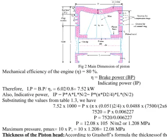
Fig 2 Main Dimension of piston
Mechanical efficiency of the engine (η) = 80 %.
η = Brake power (BP) Indicating power (IP) Therefore, I.P = B.P/ η, = 6.02/0.8= 7.52 kW
Also, Indicative power, IP = P*A*L*N/2= P*(π*D2/4)*L*(N/2) Substituting the values from table 1.3, we have
7.52 x 1000 = P x (π x (0.051)2/4) x 0.0488 x (7500/(2x60)) 7520 = P x 0.006227
P = 7520/0.006227
P = 12.08 x 10⁵ N/m2 or 1.208 MPa Maximum pressure, pmax= 10 x P, = 10 x 1.208= 12.08 MPa
Thickness of the Piston head:According to Grashoff’s formula the thicknessof the piston head is given by
tH= √ (3*P*D2) /16*σt or tH= √ (3*P*D2) /16*(σut/FOS) (since σt= σut/FOS)
= √ (3*12.08*512)/(16*480/2.25)= √94260.24/3413.3= √27.6= 5.25 mm
Radial thickness of rings:t 1 = D √ 3*pw/ σp= 51x√3 x0.025/110= 51x0.02611= 1.33mm Axial thickness of the piston:t2 = 0.7t1= 0.7x1.33= 0.932 mm ≈ 1 mm
Width of the top land (b1):b1 = tH to 1.2tH= 6.53 mm (consider b1 = tH)
Width of other lands (b2):b2 = 0.75 t2 to t2=0.75 x 1= 0.75 mm (consider b2=0.75t2)
Thk of piston barrel at the top end:t3 = 0.03D+t1+4.9= 0.03 x 51+1.33+4.9 = 7.76 mm Thk of piston barrel at the open end : t4= 0.25 t3 to 0.35 t3= 0.25 x 7.76= 1.94 mm≈ 2m Length of skirt:Ls = 0.6 D to 0.8D= 0.6 x 51= 30.6 mm
Length of piston pin in the conn. rod bushing:l1= 45% of the piston dia= 0.45 x 51= 22.95 mm Piston pin diameter:d0 = 0.28 D to 0.38 D= 0.28 x 51= 14.28 mm
Table 4- Final Dimension of piston
S/no. Description Nomencleture Value in mm 1 Thickness of piston head tH 5.25
2 Radial width of the ring t1 1.33
3 Axial thickness of the piston t2 1
4 Width of top land b1 6.53
5 Width of ring land b2 0.75
6 Thickness of piston barrel at the top end t3 7.76
7 Thickness of piston barrel at the open end t4 2.7
8 Length of skirt ls 30.6
9 Length of piston pin in the connecting rod bushing l1 22.95
10 Piston pin diameter d0 14.28
IV. GEOMETRICALMODELING AND FINITEELEMENTANALYSIS
4.1GEOMETRICALMODELING
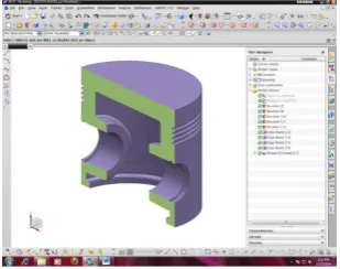
The dimension calculated for the piston according to the procedure and the specification given in the design data book are used for preparing the model using UG Nx-8 3D modelling software. Piston was modelled using UG Nx-8 software which is shown in below figure 3 and4
Fig 3- 3D- model of piston Fig 4- 3D- half section of piston
4.2MESHINGOF3DMODELOFPISTON
The element selected for meshing the piston model is solid187 tetrahedron type of element which is higher order tetrahedral element. The mesh count contains 33743 numbers of nodes and 19541 numbers of elements. Below figure shows the meshed model of piston.
4.3BOUNDARY CONDITION FOR STRUCTURE ANALYSIS (UNCOATED AND COATED PISTON)
Combustion of gases in the combustion chamber exerts pressure on the head of the piston during power stroke. The pressure force will be taken as boundary condition in structural analysis using ANSYS work bench. Fixed support has given at surface of the pin hole because the piston will move from Top dead center (TDC)to Bottom dead center (BDC) with the help of fixed support at pin hole. So whatever the load is applying on the pistons due to gas explosion causes the failure of piston pin including bending stresses. As per analytical calculation pressure acting on the piston due to combustion is 12.08 MPa.The load variation analysis is performed on piston at 100%, 125%, 150%, 175%, 200%, 225% and 250% of the calculated pressure as the load varies from 100% to 250% in Bajaj Kawasaki four stroke petrol engines
.
(a) (b)
Fig 6- Boundary condition for structural analysis (a) at 100% of load (b) at 250% of load
4.4 STRESS DISTRIBUTION AND TOTAL DEFORMATION BEFORE COATING
(a) (b)
(c) (d)
4.5BOUNDARY CONDITION FOR STRUCTURE ANALYSIS UNDER COUPLED FIELD (UNCOATED AND COATED PISTON)
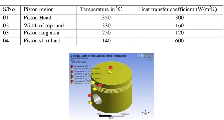
Temperature distribution, loading and Boundary condition for uncoated and coated piston. Figure shows the temperature distribution, loading and the boundary condition considered for the analysis. The temperature distribution at piston head, top land, piston ring area and piston skirt according to table 4.1 is applied for thermal analysis and the uniform pressure from 100% to 250% of calculated pressure is applied on crown of piston which is indicated by red color and the model is constrained on upper half of piston pin hole as shown by violet color.
Table 5 – Temperature and heat transfer coefficient applied to the piston
S/No Piston region Temperature in 0C Heat transfer coefficient (W/m2K) 01 Piston Head 350 300
02 Width of top land 330 160 03 Piston ring area 250 120 04 Piston skirt land 140 600
Fig8 - Temperature and convection coefficient distribution
4.6STRESS DISTRIBUTION &TOTAL DEFORMATION OF UNCOATED PISTON UNDER COUPLED FIELD
(a) (b)
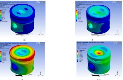
4.7STRESS DISTRIBUTION &TOTAL DEFORMATION OF COATED PISTON UNDER COUPLED FIELD
(a) (b)
(c) (d)
Fig 10- stress distribution and total deformation of coated piston under coupled field (a) Equivalent stress at 100% load (b)Equivalent stress at 250% load(c) Total deformation at 100% load (d)Total deformation at 250% load
V.RESULT
The values of equivalent stress and total deformation at different loading condition are recorded
Table 6 Static structural analysis result of uncoated piston under thermal and mechanical loads
S/no Pressure/ load (Mpa) Equivalent stress (Mpa) Total deformation (mm)
01 12.08 (100%) 524.88 0.10507
Table 7 Static structural analysis result of coated piston under thermal and mechanical loads
S/no Pressure/ load (Mpa) Equivalent stress (Mpa) Total deformation (mm)
V. CONCLUSION
The result showed that coated piston with ceramic material has better performance in stress and deformation in comparison with the aluminium alloy named A2618 under the joint action of the thermal and mechanical loads.
The preliminary thermo-mechanical FE analysis was presented in the thesis. Its main purpose was to compare behaviour of the piston made of different type of materials under thermal load. The new composite material was primarily considered due to low hysteresis of the coefficient of thermal expansion for heating and cooling. The obtained results shows that the new composite piston has around 2.5 times lower radial displacements than the actual one. Therefore, a dimensional stability of the piston is strongly improved. The radial component of the stress is also much lower for the new composite piston as well.
Combined CAD and ANSYS, get the results of stress and deformation and temperature when the piston under the mechanical loads, thermal loads and assembly the mechanical and thermal load. And get the discussion as below: 1) The temperature is higher at the combustion chamber side of the deviation from the center of the piston. Highest temperature appears in the throat of the exhaust port of the combustion chamber adjacent side, the temperature reached 350°C . The temperature of the piston ring area is extremely important for the reliability of the engine, if the temperature of the ring zone is too high, it will make the lubrication oil to be deterioration even carbonization. It causes the piston ring bonded, loss of activity to make the piston rapid wear, deformation.
2)
3) The stress under the mechanical action, the maximum stress value of the piston is 390 Mpa, and the most stress of other parts below 100Mpa. For the tensile strength of the piston, it’s having an enough strength margin.
4) When under the assembly of mechanical and thermal loads, the value of the largest displacement is 0.16 mm, causing at the center of the piston top. The stress of the top of the piston is mainly caused by the temperature load and the deformation of the piston is caused by the thermal expansion.
5)
Graph 1- showing Stress vs. Pressure/load Graph 2 - showing Deformation vs. Pressure/load
VII.FUTURE SCOPE OF WORK
Further more research is required to select the base material and coating material which has less weight and higher strength with high thermal coefficient of thermal expansion.More number of iteration is required with change the geometry of piston
REFERENCES
[1]Cuddy, M. R. &Wipke, K. B. (1997), Analysis of Fuel Economy Benefit of Drive train. Hybridization http://www.nrel.gov/vechicle fuels/vsa/pdfs/22309.pdf (National Renewable energy laboratory).
[2]F.S. Silva (2006) Fatigue on engine pistons – A compendium of case studies.EngineeringFailure Analysis, 13 pp(480–492).
[3]EkremBuyukkaya, MuhammetCerit( 2007 ) Thermal analysis of a ceramic coating diesel engine piston using 3-D finite element method. Surface and Coatings Technology 202, 2 pp( 398–402).
piston with different materials, The Iraqi Journal for Mechanical and Material Engineering, 8, 3 pp (249-256).
[5]Gudimetal P, Gopinath C.V, (2009) Finite Element Analysis of Reverse Engineered Internal Combustion Engine Piston, AIJSTPME, 2, 4 pp(85- 92).
[6]Yanxia Wang, YongqiLiu,Haiyan ( 2010), Simulation and Analysis of Thermo-Mechanical Coupling Load and Mechanical Dynamic Load for a Piston; IEEE, pp (106-110).
[7]Wu, Yi Zeng, DongjianFeng, Zhiyuan, (2010) Finite Element Analysis for the Thermal Load of Piston in a Dimethyl Ether Fueled Diesel Engine,
IEEE
[8]PiotrSzurgott and TadeaszNiezgoda, “ Thermo-mechanical FE analysis of the piston made of composite material with low hyteresis”. Journal of kones power train and transport, Vol 18 Nov 2011
[9]MesutDurat, Murat Kapsiz, Ergun Nart, FeritFicici& Adnan Parlak, (2012), The effects of coating materials in spark ignition engine design; Materials & Design, 36 PP (540-545).
[10] Ajay singhRai (2014), “Design, analysis and optimization of three aluminum piston alloys using FEA; Journal of engineering research and application. ISSN: 2248-7622 Vol.4 Issue (Version 3, January 201 pp94-102)