International Journal of Research (IJR)
e-ISSN: 2348-6848, p- ISSN: 2348-795X Volume 2, Issue 09, September 2015Available at http://internationaljournalofresearch.org
High-Frequency-Link
Vienna Rectifier with Power
Quality Added Function
K.Harsha Vardhana reddy*
1; Sadiq Ahmed Khan
2& Dr. Abdul Ahad
31M.tech (P.E) Student Department Of EEE, Nimra College Of Engineering & Technology
2 Asst. Professor Department Of EEE, Nimra College Of Engineering & Technology
3Professor & Head Of The Department, Nimra College Of Engineering & Technology
Abstract:
The aim of this paper is to introduce power quality added function to the standard Vienna rectifier in order to compensate reactive power and to cancel current-type harmonics drawn by nonlinear loads connected to the same point of common coupling. A theoretical investigation that demonstrates the ability of such topology to compensate harmonics and limited reactive power is first presented. Then, the design and implementation of a linear quadratic regulator with integral action is presented. The converter is controlled as a whole i.e., a multiple-input-multiple-output system, and uses an augmented model that was developed in the d- q frame. Experimental results obtained with a digital-signal-processor-based DS1103 controller and the converter operating at a 20-kHz switching frequency proved the effectiveness of the theoretical study and the high performance of the proposed control strategy in compensating load harmonics and limited reactive power.
Introduction
NOWADAYS, active rectifiers are widely used in industrial applications in order to meet the international power quality standards. These rectifiers ensure that the input currents have a near-sinusoidal shape and are in phase with the mains voltage .Currently, a large variety of such rectifiers is available; however, the three-phase/switch/level boost rectifier known as the Vienna rectifier has already proven its effectiveness as a high-power rectifier. The topology has fewer active switches, a smaller filter inductor size, and better efficiency compared with the traditional six-switch two-level converter. The same advantage regarding energy efficiency of the Vienna rectifier used as a machine-side converter instead of a traditional
six-switch two-level pulse width modulation (PWM) rectifier is also reported in the literature for wind energy conversion systems. Recently, efforts have been made by researchers to improve the Vienna rectifier's modeling and control and to increase its power density.
International Journal of Research (IJR)
e-ISSN: 2348-6848, p- ISSN: 2348-795X Volume 2, Issue 09, September 2015Available at http://internationaljournalofresearch.org
hand, the linear quadratic regulator (LQR) based on optimal control was successfully applied to three-phase PWM rectifiers and inverters, interfacing renewable energy sources to the utility grid using a three-level inverter and a three-phase three-wire shunt active power filter.
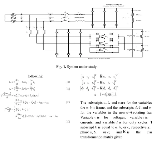
CONVERTER MODEL
The topology of the three-phase/switch/level boost rectifier known as the Vienna rectifier and
the nonlinear load represented by a three-phase
diode bridge loaded are shown in Fig. 1. A
state-space model in the – rotating reference frame at the mains angular frequency of the
Vienna rectifier is presented in [29]. The
zero-sequence components of mains voltages and currents are equal to zero for a balanced three-phase source voltage and a nonconnected neutral point. The four state variable equations describing the system dynamics in the – rotating frame are given in the
Fig. 1. System under study.
following:
The subscripts , , and are for the variables in the – – frame, and the subscripts , , and are for the variables in the new – rotating frame. Variable is for voltages, variable is for currents, and variable is for duty cycles. The subscript is equal to , , or , respectively, for
phase , , or ; and is the Park's
International Journal of Research (IJR)
e-ISSN: 2348-6848, p- ISSN: 2348-795X Volume 2, Issue 09, September 2015Available at http://internationaljournalofresearch.org
by
expressions (1a)–(1h),
and represent the state-space vector
and the control input vector, respectively. The
overall dc output voltage is , the
dc output voltage unbalance
is and represents the
difference between the upper and lower dc bus voltages, denotes the phase shift between the phase voltage and the corresponding Vienna rectifier fundamental component current, sgn represents the function signum, and is a
constant parameter theoretically equal to .
The state-space model (1a)–(1d), which is valid
for large-signal operation, is nonlinear since it contains multiplication terms of the state variables and inputs. This nonlinear model has to be linearized around a set point in order to implement a linear controller such as the LQR.
The equilibrium point is obtained by making the
time derivatives of (1a)–(1d) equal to zero and by
substituting all variables by their steady-state values. The nominal steady-state operating point when the -axis is aligned with the phase
voltage is
then
The small-signal model (3) is obtained using
linearization around the aforementioned operating point. The LQR control law essentially gives a multivariable proportional regulator. Integral action has been added to the controller in order to cancel steady-state errors. Three new states are
then added to the small-signal model. These new state variables are the integral of the state
variables , ,
and .
Thus
In (3b)–(3d), vectors , , and are the
augmented state, control, and disturbance vectors, respectively.
The matrices , , and , which represent the
International Journal of Research (IJR)
e-ISSN: 2348-6848, p- ISSN: 2348-795X Volume 2, Issue 09, September 2015Available at http://internationaljournalofresearch.org
as
wherethe duty cycles in steady-state are given
by
Equation (1d), which represents the power
balance between the ac and dc sides of the
converter, gives for a lossless
one
For the converter including power quality added function, in order to compensate for reactive power, the -component of the Vienna rectifier
is computed as follows:
In the preceding equation, represents the
-component of the fundamental currents drawn by the nonlinear load,
SIMULATION RESULTS & DISCUSSIONS
The system's response, as obtained on the matlab-based control algorithm, is presented here. The
weighting matrix and weight have been set
to values that guarantee satisfactory response. It is a heuristic method, and it is important to point out that increasing the weight for a variable leads to a speedup of its response and vice versa. Weights
and are chosen to get duty cycles between
zero and one and a settling time between one and two cycles of the supply mains. These values are first generated by simulation-based examination of the responses obtained using MATLAB's Sim
Power Systems and Simulink,
i.e.,
A. Standard Vienna Rectifier
Fig.2 shows the phase voltage , line current ,
upper dc bus voltage , and the opposite of the
lower dc bus voltage when switch S is open
(the three-phase nonlinear load is not connected) and the value of the resistors at the dc side of the
International Journal of Research (IJR)
e-ISSN: 2348-6848, p- ISSN: 2348-795X Volume 2, Issue 09, September 2015Available at http://internationaljournalofresearch.org
Fig. 2. Phase voltage (ch1), upper dc bus voltage (ch2), opposite of the lower dc bus voltage (ch13), and source current (ch4) waveforms of the standard Vienna rectifier.
Fig. 3. Source voltage (ch1), source current (ch3), nonlinear load current (ch2), andVienna rectifier with power quality added function current (ch4)waveforms
The measured characteristics of phase voltages
and line currents are summarized in Table I.
TABLE I PHASE VOLTAGES
AND LINE CURRENTS CHARACTERISTICS
The measured characteristics of power are
summarized in Table II.
TABLE II POWER CHARACTERISTICS
The controller ensures the equalization of voltages
across the two capacitors and
tracking of the overall dc bus voltage, which is equal to its reference value. In addition, one can observe that the harmonic content and the displacement factor are kept under control. The source current's measured total harmonic distortion (THD) is equal to 2.2% for a fundamental component of 10.07 A, and that of the source voltage is also equal to 2.2%. This demonstrates the unity power factor operation of the standard Vienna rectifier.
B. Vienna Rectifier With Power Quality Added Function
1) Steady-State Regime
Fig. 3 shows from top to bottom the phase voltage , source current , nonlinear load
current , and Vienna rectifier current
when switch S is closed (the three-phase nonlinear load is now connected with , and the value of the resistors at the dc side of the Vienna rectifier is. The measured characteristics of nonlinear load and line
TABLE III NONLINEAR LOAD
AND LINE CURRENTS CHARACTERISTICS
The measured characteristics of nonlinear load and source power when the Vienna rectifier is supplying 1.8 kW to the dc load are summarized in Table IV.
TABLE IV NONLINEAR LOAD
AND SOURCE POWER CHARACTERISTICS
One can observe that the controller ensures the equalization of voltages across the two
capacitors and tracking of the
International Journal of Research (IJR)
e-ISSN: 2348-6848, p- ISSN: 2348-795X Volume 2, Issue 09, September 2015Available at http://internationaljournalofresearch.org
the harmonic content and the displacement factor are kept under control.
The THD value of the measured line currents is 3.9% for a fundamental component of 7.54 A. The measured THD value of the nonlinear load currents is 24.5% for a fundamental component of 2.48 A. It can be observed from these results the ability of the Vienna rectifier with power quality added function to provide the required compensation for harmonics and reactive power.
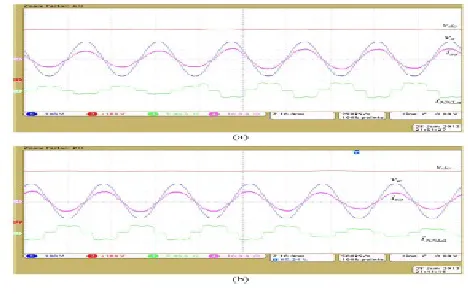
DYNAMIC REGIME
Fig. 4 (a) and (b) shows, when switch S is also closed, from top to bottom the overall dc bus
voltage , phase voltage , source current ,
and the nonlinear load current when a sudden variation of the three-phase nonlinear load occurs. The power transmitted to the load has been increased from 50% to 100% and back to its initial value (is switched from 160 to 80 and back to 160 ). Compensation is achieved before and after load changes. The controller ensures tracking of the dc bus voltage, and the steady-state error is zero. A small overshoot–undershoot (4%) and a short settling time of the dc bus voltage (one cycle of the mains) for these load power variations can be noticed. In addition, one can observe that the harmonic content, as well as the compensation, is kept under control.
Fig.4. Overall dc bus voltage (ch2), phase voltage (ch1) source current (ch3), and nonlinear load current (ch4) of the Vienna rectifier with power
quality added function current waveforms for nonlinear load variation. (a) From 50% to 100%.
(b) From 100% to 50%.
CONCLUSION
International Journal of Research (IJR)
e-ISSN: 2348-6848, p- ISSN: 2348-795X Volume 2, Issue 09, September 2015Available at http://internationaljournalofresearch.org
inductor is used. The active power of the nonlinear load is equal to that of the Vienna rectifier for a commutation reactance as high as 0.1628 p.u. in the nonlinear load basis. An LQRI based on an extended small-signal state-space averaged model of the Vienna rectifier in the rotating – reference frame, including an integral action to complement the standard LQR and incorporating power quality added function, is then designed and implemented. The experiments that were carried out to compensate the current harmonics and the reactive power drawn by a diode bridge type of nonlinear load have proven the validity of the theoretical study and the effectiveness of the adopted control strategy
REFERENCES
[1.]J. W. Kolar and T. Friedli “The essence of
three-phase PFC rectifier systems¿¿¿Part I” IEEE Trans. Power Electron., vol. 28, no. 1, pp. 176-198, 2013
[2.]H. Y. Kanaan and K. Al-Haddad “Three-phase
current-injection rectifiers: Competitive
topologies for power factor correction” IEEE Ind. Electron. Mag., vol. 6, no. 3, pp. 24-40, 2012
[3.]T. B. Soeiro and J. W. Kolar “Analysis of
high-efficiency phase two- and three-level unidirectional hybrid rectifiers” IEEE Trans. Ind. Electron., vol. 60, no. 9, pp. 3589-3601, 2013
BIBLIOGRAPHY
Kartham Harsha Vardhana Reddy: pursuing M.Tech in Nimra College of engineering and
technology, Jupudi, Ibrahimpatnam. His
specialization in power electronics. He graduated in Electrical and Electronics Engineering from
R.S.R engineering and college,
KADANUTHALA,SPSR NELLORE. Mail
Sk Sadik Ahmed Khan: is currently working as an ASSISTANT PROFESSOR in Electrical and Electronics Engineering department at Nimra College of engineering and technology (NCET) Jupudi, Ibrahimpatnam. He obtained his M TECH degree in power Electronics MAIL ID