Article
Combination of Laser Material Deposition and Laser
Surface processes for the manufacture of sculptured
surface components
Jon Iñaki Arrizubieta 1, *, Magdalena Cortina 1, Jose Exequiel Ruiz 1, Aitzol Lamikiz1
1 Department of Mechanical Engineering, University of the Basque Country, Plaza Torres Quevedo 1, 48013 Bilbao, Spain; joninaki.arrizubieta@ehu.eus (J.I.A.); magdalena.cortina@ehu.eus (M.C.);
joseexequiel.ruiz@ehu.eus (J.E.R.); aitzol.lamikiz@ehu.eus (A.L.) * Correspondence: joninaki.arrizubieta@ehu.eus; Tel.: +34-946-013-932
Abstract: The present work proposes a novel manufacturing technique based on the combination of Laser Metal Deposition, Laser Beam Machining and Laser Polishing processes for the complete manufacturing of complex parts. Therefore, the complete process is based on the application of a laser heat source both for the building of the preform shape of the part by additive manufacturing and for the finishing operations. Their combination enables to manufacture near-net-shape parts and afterwards, remove the excess material via laser machining, which has resulted to be capable of eliminating the waviness resulting from the additive process. Besides, surface quality is improved via laser polishing to reduce the roughness of the final part. Therefore, conventional machining operations are eliminated, what results in a much cleaner process. In order to validate the capability of this new approach, the dimensional accuracy and surface quality of the resulting parts are evaluated. The process has been validated on an Inconel 718 test part, where a previously additively built up part has been finished by means of laser machining and laser polishing.
Keywords: laser; additive manufacturing; laser beam machining; laser polishing; waviness; roughness; Inconel 718.
1. Introduction
Laser Material Processing is an alternative to many traditional manufacturing processes, such as arc welding, electrochemical machining, hand polishing, electron beam welding, etc. Laser Material Processing main characteristic is the use of a high power laser as a heat source, which results in a very high concentration of the energy density that reduces the Heat Affected Zone (HAZ) and thermally induced distortions [1].
One of the laser-based processes that is experimenting a continuous growth is the Laser Metal Deposition (LMD). This Additive Manufacturing (AM) process consists on generating a melt pool on the surface of the substrate, while wire or powder shaped filler material is added simultaneously [2]. Besides, LMD enables to obtain near-net-shape parts, what reduces the amount of wasted material [3, 4]. With regard to environmental impact considerations, if material reductions as high as 50% with respect to the initial part are required during the manufacturing process, AM becomes environmentally friendlier compared with machining and forging [5]. In the same way, the aeronautical industry uses the buy-to-fly ratio as an efficiency factor, since it relates the weight of the part that really flights with the weight of the initial part stock. Laser Material Deposition can reduce the buy-to-fly ratio below 1,5:1, comparable to laser welding processes [6]. However, LMD manufactured parts do not meet the final surface roughness and dimensional requirements, and a finishing operation is always required [7]. Usually, conventional machining is applied for the finishing of the parts.
Another laser-based process that has found a niche in the market is the Laser Beam Machining (LBM), where the laser beam is directly applied for melting and vaporizing unwanted material from
the substrate surface [8]. As the LBM is a laser-based process, no cutting tools are required and materials can be machined regardless their hardness [9]. In addition, LBM process applies a laser beam (usually smaller than 75 m beam diameter) directly for removing surface material. Therefore, this process is especially suitable for the machining of small details on hard materials [10]. Moreover, high aspect-ratio grooves and holes can also be achieved [11] and almost no HAZ is generated when nano or femto pulse-duration lasers are used [12]. Nevertheless, as Dubey et al. stated, LBM process is not fully developed and it is still waiting to its industrial use [8].
LBM does not always provide the desired surface quality and a finishing operation is required. To this end, highly skilled operators using abrasive tools have traditionally performed finishing operations manually. For instance, Peng et al. proposed the Abrasive Flow Machining for removing the falling effect and the powder adhesion generated during AM [13].
An alternative to reduce the surface roughness of previously manufactured parts, which has caught the interest of many researchers, is the Laser Polishing (LP) [14,15,16]. In LP, peaks of the surface roughness are melted and the material is redistributed in the valleys due to the surface tension and the gravity [17]. Therefore, when laser polishing, material is not removed nor the final shape of the part is modified, but material is relocated while melted. In order to improve the understanding of the effect of LP on additively manufactured parts, Marimuthu et al. studied the influence of the melt pool dynamics on the resulting surface topology and roughness [18].
Other authors have studied experimentally the improvement of the surface quality when AM and LP are combined. For example, Zhihao et al. studied the surface roughness reduction of additively built up parts using laser polishing [19]. They concluded that LP improves the surface roughness of Inconel 718 Selective Laser Melting (SLM) manufactured parts. On the other hand, Ma et al also studied the improvement of the surface roughness of additively manufactured Ti alloys [17]. Nevertheless, the reference surface on which authors applied LP was a W-EDM cut surface and not the wavy surface characteristic of AM.
Up to now, the roughness and excess material resulting from the AM process is eliminated mechanically via milling or other abrasive processes, such as grinding. In this direction, the current trend of modern industry is to combine additive and subtractive technologies within the same machine [20]. However, laser-based processes are not always easily combined with other manufacturing techniques. For instance, the combination of LMD with milling or turning may result problematic, especially when cutting fluids are used. The problems arisen can be classified in two groups. On the one hand, the handling and filtering of the moisture generated when the powder particles and the cutting fluid are mixed results problematic. On the other hand, pore phenomena do appear if the surface is not properly cleaned before the LMD process [21].
Consequently, if LMD, LBM and LP processes are combined, the machining operation could be eliminated from the production chain, what leads to a much cleaner and environmentally friendlier manufacture. Moreover, the use of coolants, tooling, etc. is eliminated, what simplifies the management of the generated residues during the manufacturing process.
In order to demonstrate the validity of this statement, a novel manufacturing procedure, fully based on laser, that combines LMD, LBM and LP technologies is developed, where Laser Beam Machining is employed for removing the overstock and waviness generated by Laser Material Deposition. Finally, Laser Polishing is used for reducing the roughness resulting from the Laser Beam Machining process. Topographies of the attained surfaces are extracted for each operation and roughness values are measured in order to evaluate the surface quality.
2. Materials and Methods
has been employed for the LMD tests. Powder material is supplied using a Sulzer Metco Twin 10 C powder feeder and focused by an in house designed coaxial nozzle, denominated as EHUCoax-2015 [22]. Argon has been used as protective and carrier gas. Then, a Trumpf TruMark Station 5000 is used for the LBM and LP operations [23]. This marking station has a fiber laser with a Q-switch pulse technology that concentrates a 50 W laser power in 7-500 ns duration pulses.
The material used for the tests is Inconel 718 superalloy, which is supplied by Oerlikon Metco under the name MetcoClad 718. The chemical composition of the powder material is shown in Table 1 and, as it can be observed, it is similar to that of Inconel 718. Powder is supplied with a grainsize between 44 and 90 microns in diameter and the spherical shape of the particles is ensured as they are manufactured via Argon-gas atomization.
Table 1. Chemical composition (wt. %) of the MetcoClad 718 [24].
Cr Mo Nb Fe Ti Si Mn C B Ni
19 3 5 18 1 0.2 0.08 0.05 0.005 Bal.
Before manufacturing a final test part, three types of tests are performed:
(1) First, a preliminary test (Test Part 1) for evaluating the capability of LBM for machining LMD manufactured Inconel 718 is performed. For this purpose, a 3 mm thickness layer is deposited by means of LMD. Afterwards, the surface of the deposited material is grinded in order to ensure a flat reference surface. On this surface, different LBM parameters are tested and in each case, the reached depth and the resulting surface quality are evaluated. Based on the obtained results, the maximum effective depth at which the laser could remove material is defined.
(2) Secondly, and based on the results obtained in Test 1, the capability of LP for improving the roughness resulting from LBM is evaluated. Based on these results, the optimum LP parameters are defined.
(3) Finally, the capability of LBM for eliminating the surface waviness resulting from LMD is evaluated. In this case, no intermediate grinding operation is performed.
Process parameters for LMD of MetcoClad 718 were obtained in a previous work [21] and are detailed in Table 2. In Figure 1 a cross section of a single clad is shown, where the dimensions and dilution can be observed. The sample is etched using Kalling´s 2 reagent in order to reveal the microstructure originated during the cooling stage. Generated clads have 2 mm width and a constant 0.8 mm height is obtained with each layer.
Table 2. LMD process parameters for the MetcoClad 718 [9].
Process parameter Value
Continuous wave laser power (W) 570 Scan velocity (mm·min-1) 525
Track offset (mm) 1.036
Overlap between tracks (%) 26 Powder mass flow (g·min-1) 8.78
Figure 1. a) Cross section of a single clad; b) detail of the microstructure.
For the first test, material is deposited over an AISI 1045 substrate. This substrate has no influence on the subsequent LBM operations, since they are performed only in the LMD zone. Nevertheless, for the final tests, Inconel 718 substrate has been used. Figure 2 shows the substrate with the deposited area after the grinding operation.
Figure 2. Test part 1 after the LMD and grinding processes.
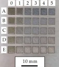
In order to determine the best conditions for LBM, a parameter scanning has been performed over the flat surface obtained in Test Part 1. Obtained results are shown in Figure 3, whereas the employed parameters in these tests are showed in Table 6 (see Appendix A). Process parameters corresponding to the test A4 are considered the best in terms of penetration and low recast layer; therefore, these parameters are employed for the following LBM operations, see Tables 3 and 4.
Figure 3. Parameter tests for obtaining the best LBM conditions (Test Part 1)
Figure 4. Parameter tests for obtaining the best LP conditions (Test Part2)
Table 3. LBM and LP parameters for the MetcoClad 718.
Process parameter LBM LP
Power (%) 100 100
Velocity (mm·s-1) 800 100
Pulse frequency (Hz) 372000 175000
Pulse duration (ns) 20 460
Defocusing (mm) 0 4
Table 4. Hatching parameter values for LBM and LP.
Process parameter LBM LP
Line spacing (mm) 0.05 0.02
Number of hatchings (-) 20 10
Angle increment (°) 17 36
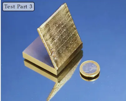
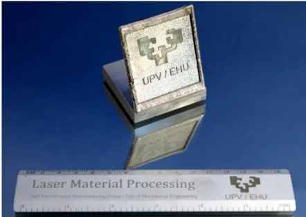
Once Test 1 and 2 are carried out and parameters for LBM and LP are defined, a Test 3 is performed on a part manufactured by LMD. The test part shown in Figure 5 (which is also used for manufacturing the final part shown in Figure 12) has been manufactured layer-by-layer by LMD. The result is a 50 mm high wall with a 4 mm thickness and 60° inclination. Note that in this test, no grinding operation is executed and surface waviness resulting from the LMD process is eliminated exclusively via LBM.
3. Results
3.1. Material removal via LBM
First, LBM is performed on the surface of the Test Part 1, with the laser beam focused on its surface and without changing the focal position between the consecutive repetitions. After every 10 repetitions, the mark generated on the surface of the substrate is analyzed by means of a Leica DCM 3D confocal microscope. In Figure 6, the topographies of two different marks are shown.
Figure 6. Topographies of the mark after (a) one repetition; (b) 10 repetitions.
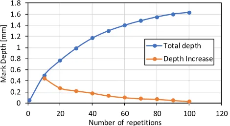
As the number of repetitions is increased, the depth increment is lower, and after 100 repetitions, it is noticed that the laser is not capable of removing more material. Therefore, the LBM process is concluded to be capable of removing material until a 1.6 mm maximum distance from the focal plane position (fpp), see Figure 7. It must be highlighted that the laser beam is focused on the original grinded surface of the substrate and its position remains unchanged as the number of repetitions is increased.
Figure 7. Depth increase as the number of repetitions is increased.
3.2. Roughness reduction via LP
The idea of combining LMD and LBM processes arises as a methodology aiming to remove the surface waviness that LMD generates and thus, obtain a flat surface. To that end, the laser is defocused 1 mm above the desired final surface. Therefore, the laser eliminates the all material until a 1.6 mm distance from the focal plane position, see Figure 8, and the process does only affect material located in this concrete region. However, as the resulting surface quality from the LBM process has a high roughness value, Figure 10, a polishing stage is afterwards performed, Figure 11.
0 0.2 0.4 0.6 0.8 1 1.2 1.4 1.6 1.8
0 20 40 60 80 100 120
M
ar
k
D
ep
th
[m
m
]
Number of repetitions
Figure 8. Followed strategy in LBM for obtaining a flat surface from the waved LMD surface. a) LMD manufactured part; b) Material removal via LBM; c) resulting flat surface after LBM.
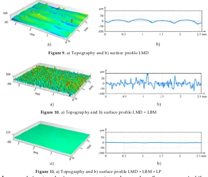
A 3D view of the surface attained after the different laser-based processes is shown in Figures 9-11. In the three figures, the same height axis scale is used in order to make results visually comparable. In the case of the LMD surface, roughness is measured perpendicularly to the LMD direction, because the LMD is a directional process and so is the resulting surface pattern. On the contrary, in LBM and LP the hatching direction is changed in every repetition in order to avoid any directional pattern on the surface, and therefore, roughness is independent from the measured direction.
Figure 9. a) Topography and b) surface profile LMD
Figure 10. a) Topography and b) surface profile LMD + LBM
Figure 11. a) Topography and b) surface profile LMD + LBM + LP
In a second step, in order to compare numeric roughness values, the measurement of the roughness of each surface has been carried out. The arithmetic mean deviation of the surface roughness (Ra) of five different profiles is measured in each surface and the average value is calculated. Measurements are performed according to the standard ISO 4287. As it is shown in Table 5, the Ra value is higher after the LBM process, than that after the LMD. However, LBM provides a waviness-free surface, but the roughness needs to be reduced with the subsequent polishing stage.
fpp 1.6
m
m
Removed material
Final surface
Deposited material
a) b) c)
Laser beam
1
m
Table 5. Arithmetic Mean Deviation of the Roughness Profile (Ra) in microns, according to ISO 4287. 0.25mm Gaussian filter applied.
Measurement LMD LBM LM
1 1.56 20.45 0.53
2 2.38 20.24 0.66
3 1.32 20.21 0.57
4 4.07 1 24.80 0.71
5 2.01 16.17 0.56
Average Ra 2.27 20.37 0.61
1 Higher surface roughness value is obtained because of a powder particle adhered to the surface is caught in the
measurement.
3.3. Final test part
In order to demonstrate the potential of combining LMD, LBM and LP processes, a final test part is manufactured, Figure 12. First, starting from an Inconel 718 substrate, an oblique wall is built using MetcoClad 718 filler material with the same strategy and conditions used in the previous tests. Afterwards, the wavy surface resulting from the LMD is processed via LBM up to a 0.5 mm depth. Finally, the desired regions are laser polished.
Figure 12. Final shape of the manufactured final test part.
4. Discussion
In the present work, a full laser-based manufacturing technique is proposed. According to the attained results, the following conclusions are drawn:
(1) The LBM process is proved to be capable of eliminating the waviness generated in the LMD process and enables to obtain a flat surface.
(2) Surface quality resulting from LBM may not comply with the desired requirements. However, high surface quality (N5-N6 roughness grade) is obtained after the LP stage. (3) The LBM process is proved to be slow compared with the machining processes. Therefore,
the combination of LMD+LBM is only advantageous when difficult-to-cut materials are processed or high resolution detail operations are required.
(4) The LBM process is capable of manufacturing small details that may not be possible to attain with other traditional machining processes, such as milling.
Funding: This research received no external funding.
Acknowledgments: Special thanks are addressed to the Industry and Competitiveness Spanish Ministry for the support on the DPI2016-79889-R INTEGRADDI project and PARADDISE project H2020-IND-CE-2016-17/H2020-FOF-2016 of the European Union’s Horizon 2020 research and innovation program.
Conflicts of Interest: The authors declare no conflict of interest.”
Appendix A
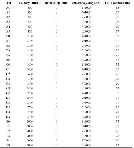
Process parameters for LBM tests carried out in order to determine the optimal parameters. In all tests the hatching parameters are kept constant according to the values detailed in Table 4 (line spacing of 0.05 mm and 20 hatching with an angle increment of 17°).
Table 6. LBM process parameters
Test Velocity [mm·s-1] defocusing (mm) Pulse frequency [Hz] Pulse duration [ns]
A0 800 0 144000 55
A1 800 0 201000 37
A2 800 0 258000 27
A3 800 0 315000 23
A4 800 0 372000 20
A5 800 0 429000 17
B0 1100 0 144000 55
B1 1100 0 201000 37
B2 1100 0 258000 27
B3 1100 0 315000 23
B4 1100 0 372000 20
B5 1100 0 429000 17
C0 1400 0 144000 55
C1 1400 0 201000 37
C2 1400 0 258000 27
C3 1400 0 315000 23
C4 1400 0 372000 20
C5 1400 0 429000 17
D0 1700 0 144000 55
D1 1700 0 201000 37
D2 1700 0 258000 27
D3 1700 0 315000 23
D4 1700 0 372000 20
D5 1700 0 429000 17
E0 2000 0 144000 55
E1 2000 0 201000 37
E2 2000 0 258000 27
E3 2000 0 315000 23
E4 2000 0 372000 20
Appendix B
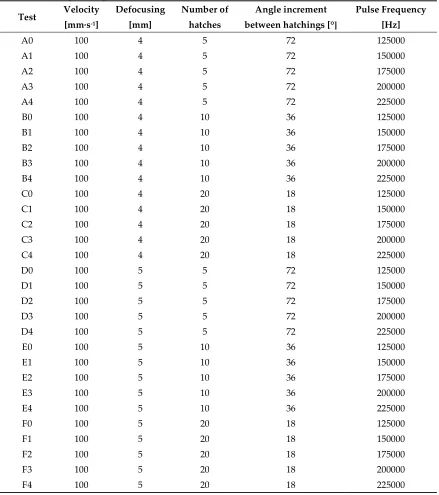
Process parameters for LP are shown in the following Table 7. In all tests, the line spacing is kept constant with a value of 0.02 mm. The angle increment between the hatchings is defined in order to sweep a total angle of 360° with the defined number of hatches..
Table 7. LP process parameters
Test Velocity [mm·s-1]
Defocusing [mm]
Number of hatches
Angle increment between hatchings [°]
Pulse Frequency [Hz]
A0 100 4 5 72 125000
A1 100 4 5 72 150000
A2 100 4 5 72 175000
A3 100 4 5 72 200000
A4 100 4 5 72 225000
B0 100 4 10 36 125000
B1 100 4 10 36 150000
B2 100 4 10 36 175000
B3 100 4 10 36 200000
B4 100 4 10 36 225000
C0 100 4 20 18 125000
C1 100 4 20 18 150000
C2 100 4 20 18 175000
C3 100 4 20 18 200000
C4 100 4 20 18 225000
D0 100 5 5 72 125000
D1 100 5 5 72 150000
D2 100 5 5 72 175000
D3 100 5 5 72 200000
D4 100 5 5 72 225000
E0 100 5 10 36 125000
E1 100 5 10 36 150000
E2 100 5 10 36 175000
E3 100 5 10 36 200000
E4 100 5 10 36 225000
F0 100 5 20 18 125000
F1 100 5 20 18 150000
F2 100 5 20 18 175000
F3 100 5 20 18 200000
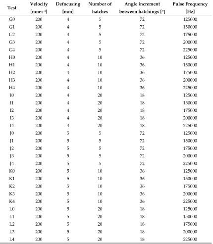
Table 7. LP process parameters (continuation)
Test Velocity [mm·s-1]
Defocusing [mm]
Number of hatches
Angle increment between hatchings [°]
Pulse Frequency [Hz]
G0 200 4 5 72 125000
G1 200 4 5 72 150000
G2 200 4 5 72 175000
G3 200 4 5 72 200000
G4 200 4 5 72 225000
H0 200 4 10 36 125000
H1 200 4 10 36 150000
H2 200 4 10 36 175000
H3 200 4 10 36 200000
H4 200 4 10 36 225000
I0 200 4 20 18 125000
I1 200 4 20 18 150000
I2 200 4 20 18 175000
I3 200 4 20 18 200000
I4 200 4 20 18 225000
J0 200 5 5 72 125000
J1 200 5 5 72 150000
J2 200 5 5 72 175000
J3 200 5 5 72 200000
J4 200 5 5 72 225000
K0 200 5 10 36 125000
K1 200 5 10 36 150000
K2 200 5 10 36 175000
K3 200 5 10 36 200000
K4 200 5 10 36 225000
L0 200 5 20 18 125000
L1 200 5 20 18 150000
L2 200 5 20 18 175000
L3 200 5 20 18 200000
L4 200 5 20 18 225000
References
1. Steen, W.M., Mazumder, J. Laser Material Processing, 4th ed; Springer-Verlag London; 2010. ISBN 978-1-84996-062-5.
2. Cortina, M., Arrizubieta, J.I., Calleja, A., Ukar, E., Alberdi, A. Case study to illustrate the potential of conformal cooling channels for hot stamping dies manufactured using hybrid process of Laser Metal Deposition (LMD) and milling. Metals 2018, 8, 102. DOI 10.3390/met8020102
4. Ashby, M.F., Materials and the Environment: Eco-informed Material Choice; Butterworth-Heinemann, 2012. ISBN 9780123859716
5. Ingarao, G., Priarone, P. C., Deng, Y., Paraskevas, D. Environmental modelling of aluminium based components manufacturing routes: Additive manufacturing versus machining versus forming. Journal of Cleaner Production 2018, 176, 261-275. DOI 10.1016/j.jclepro.2017.12.115
6. Caiazzo, F.; Alfieri, V.; Corrado, G.; Argenio, P.; Barbieri, G.; Acerra, F.; Innaro, V. Laser Beam Welding of a Ti–6Al–4V Support Flange for Buy-to-Fly Reduction. Metals 2017, 7, 183.
7. Gasser, A. Chapter 11.6: Laser Metal Deposition. In Tailored light 2, Laser Application Technology; Poprawe, R.; Springer-Verlag Berlin Heidelberg, 2011, pp. 216-224. ISBN 978-3-642-01236-5.
8. Dubey A.K. , Yadava V. Laser beam machining—A review. Int. J. Mach. Tools. Manuf. 2018, 48, 609–628 . DOI 10.1016/j.ijmachtools.2007.10.017
9. Borse, S.C., Kadam, M.S.. Experimental Study in Micromilling of Inconel 718 by Fiber Laser Machining. Procedia Manuf 2018, 20, 213-218. DOI 10.1016/j.promfg.2018.02.031
10. Yilbas, B.S. Laser Machining Processes. Reference Module in Materials Science and Materials Engineering, from Comprehensive Materials Finishing 2017, 1, 344-363. DOI 10.1016/B978-0-12-803581-8.09157-8
11. Lee, S.W., Shin, H.S., Chu, C.N. Fabrication of micro-pin array with high aspect ratio on stainless steel using nanosecond laser beam machining. Appl Surf Sci 2013, 264, pp. 653-663. DOI 10.1016/j.apsusc.2012.10.087 12. Kononenko, T.V., Freitag, C., Sovyk, D.N., Lukhter A.B., Skvortsov, K.V., Konov, V.I. Influence of pulse
repetition rate on percussion drilling of Ti-based alloy by picosecond laser pulses. Opt. Lasers Eng. 2018, 103, 65-70. DOI 10.1016/j.optlaseng.2017.12.003
13. Peng, C., Fu, Y., Wei, H., Li, S., Wang, X., Gao, H. Study on improvement of surface roughness and induced residual stress for Additively Manufactured metal parts by Abrasive Flow Machining. Procedia CIRP 2018, 71, 386-389. DOI 10.1016/j.procir.2018.05.046
14. Willenborg, E. Chapter 11.3: Polishing with Laser Radiation. In Tailored light 2, Laser Application Technology; Poprawe, R.; Springer-Verlag Berlin Heidelberg, 2011, pp. 196-202. ISBN 978-3-642-01236-5.
15. Alfieri, V., Argenio, P., Caiazzo, F., Sergi, V.. Reduction of Surface Roughness by Means of Laser Processing over Additive Manufacturing Metal Parts, Materials 2017, 10, 30. doi:10.3390/ma10010030
16. Dewey, M.P., Ulutan, D. Development Of Laser Polishing as an Auxiliary Post-Process To Improve Surface Quality In Fused Deposition Modeling Parts. Proceedings Of the ASME 12th International Manufacturing Science And Engineering Conference 2017, 2. DOI: 10.1115/MSEC2017-3024.
17. Ma, C.P., Guan, Y.C., Zhou, W. Laser polishing of additive manufactured Ti alloys. Opt. Lasers Eng. 2017, 93, 171-177. DOI 10.1016/j.optlaseng.2017.02.005
18. Marimuthu, S., Triantaphyllou, A., Antar, M., Wimpenny, D., Morton, H., Beard, M. Laser polishing of selective laser melted components. Int. J. Mach. Tools Manuf. 2015, 95, 97-104. DOI 10.1016/j.ijmachtools.2015.05.002
19. Zhihao, F., Libin, L., Longfei, C., Yingchun, G. Laser Polishing of additive Manufactured Superalloy. Procedia CIRP 2018, 71, 150-154. DOI 10.1016/j.procir.2018.05.088
20. Flynn, J.M., Shokrani, A., Newman, S.T., Dhokia, V. Hybrid additive and subtractive machine tools-Research and industrial developments. Int. J. Mach. Tools Manuf. 2016, 101, 79-101. DOI 10.1016/j.ijmachtools.2015.11.007
21. Cortina, M., Arrizubieta, J.I., Ukar, E., Lamikiz, A. Analysis of the Influence of the Use of Cutting Fluid in Hybrid Processes of Machining and Laser Metal Deposition (LMD). Coatings 2018, 8, 61. DOI 10.3390/coatings8020061
22. Arrizubieta, J.I., Tabernero, I., Ruiz, J.E., Lamikiz, A., Martínez, S., Ukar, E. Continuous coaxial nozzle design for LMD based on numerical simulation. Phys Procedia 2014, 56, 429-438. DOI 10.1016/j.phpro.2014.08.146
23. TruMark Station 5000. Available online: https://www.trumpf.com/en_INT/products/machines-systems/marking-systems/trumark-station-5000/ (accessed on 11 June 2018).
![Table 1. Chemical composition (wt. %) of the MetcoClad 718 [24].](https://thumb-us.123doks.com/thumbv2/123dok_us/7970104.1321736/3.612.185.427.518.625/table-chemical-composition-wt-metcoclad.webp)