Analysis and Developments of SUV Vehicle
Chassis using Finite Element Method
Selvamanikandan.M
1, Venkatesan.S
2P.G. Scholar, Department of Mechanical Engineering, VMKV Engineering College, Salem, Tamil Nadu, India1
Professor, Department of Mechanical Engineering, VMKV Engineering College, Salem, Tami Nadu, India2
ABSTRACT: The chassis is one of the vehicle's main assemblies and all subassemblies are connected to the chassis.Upper body and pay loads are transferred to the wheels through the chassis. This chassis development is used for M1 category SUV vehicles. At the vehicle level, the engine, radiator, fuel tank, power transmission and suspension are connected to the chassis. Therefore, this various assembly must be represented in sub-assembly level developments. This assembly is represented by a lumped mass element with COG and connected to the corresponding mounting position by an RBE3 element. This assembly has been tested with the FEA solver for various load cases, including 1 or 3 gravity fields, natural frequencies, bending, torsion, uphill combinations, acceleration and cornering, pothole and cornering case inertial relaxation. This chassis should meet the requirements with minimal deflection and no failure in all load cases. In this study, the performance of the chassis is improved by adjusting the section modulus of the ladder frame without greatly changing the mass value. The main challenge is also that the chassis front member deforms and absorbs the collision energy during vehicle collisions, to reduce the G-force and intrusion in the passenger compartment, so that the strength of the chassis should increase without affecting the flexibility.
KEYWORDS: Chassis, M1-Vehicle, FEA Simulation, Chassis development, Chassis Performance, 1G, 3G, Natural Frequency, Modal Analysis, Bending Analysis, Twisting Analysis, Combination of uphill, acceleration and cornering Analysis, Inertia relief Analysis, pot hole Analysis, cornering Analysis.
I. INTRODUCTION
The chassis is the important structural of a Vehicle, which is used to connect the entire subassembly to the vehicle. As the vehicle travels, the chassis is subjected to dynamic forces from road surface roughness, and vibration of engine and transmission system. Due to the Static forces and dynamic excitation, the chassis tends to vibrate, leading to ride comfort, ride comfort and structural stability issues. These mechanical problems involve complex nonlinear boundary conditions that are difficult to solve mathematically by analytical techniques. This difficulty is overcome by seeking some form of numerical solution. Finite element method (FEM) is the most appropriate and accurate numerical method for solving complex problems.
II. FINITE ELEMENT METHOD - MODEL INFORMATION
FEA is a powerful mathematical method to solve the complex nonlinear mathematical problems with computers. Chassis design model is converted from design model to the FEA model by using appropriate elements and joints.
2.1 Elements parameters
The sheet parts of the chassis are model with shell elements (Quad and Tria). The meshing are made in the mid plane of the components and thickness assigned to that elements, These elements will extrude both side equally to represent the thickness. Bolts are model with 1D-beam elements with corresponding diameters. Welds are represented by using rigid RBE2 elements.
Elements average size is 5mm. and the quality parameters are shown in the fig2.1
Figure 2.1 Element Quality Parameters of Chassis Mesh
2.2 Assembly mass and COG information
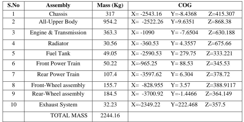
The assembly of vehicle is represented by mass elements with their COG point location. Since, modeling of full assembly will increase the run time with much change in the results. The mass and center of gravity details are shown in the table 2.1
Table 2.1 Mass and COG information of Vehicle
S.No Assembly Mass (Kg) COG
1 Chassis 317 X= -2543.16 Y=-8.4368 Z=415.307 2 All-Upper Body 954.2 X= -2522.26 Y=9.6351 Z=868.38
3 Engine & Transmission 363.3 X= -1090 Y= -7.6504 Z=630.188
4 Radiator 30.56 X= -360.53 Y= 4.3557 Z=675.66
5 Fuel Tank 49.05 X= -2590.53 Y= 279.75 Z=333.221
6 Front Power Train 50.22 X=-965.25 Y= 88.53 Z=345.53
7 Rear Power Train 107.4 X= -3597.62 Y= 6.304 Z=378.72
8 Front-Wheel assembly 155.7 X= -828.955 Y= 3.57 Z=388.9117 9 Rear-Wheel assembly 184.5 X= -3700.92 Y=-1.4466 Z=364.149
10 Exhaust System 32.23 X=-2349.22 Y=222.468 Z=357.5
Figure 2.2.1 vehicle subassembly
III.DESIGN AND DEVELOPMENTS OF CHASSIS PARAMETERS
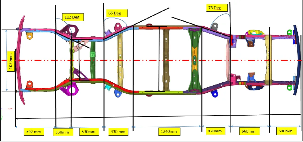
The Chassis Design and dimensions are shown in the fig 3.1, the overall dimension is 4922mmX 1030mm.
In the Study Flat ladder chassis consider for the SUV vehicle and the mounting coordinates are fixed based on the sub assembly design, so the chassis developments should perform without changing the mounting locations.
Figure 3.1 Chassis Dimension
3.1 Various Design of Chassis Frames:
DV4 (Final) different thickness (2.6mm~3.7) Double C Section frames.
Figure 3.2 Chassis various Design Improvements
Figure 3.3 Different thickness of Ladder frames
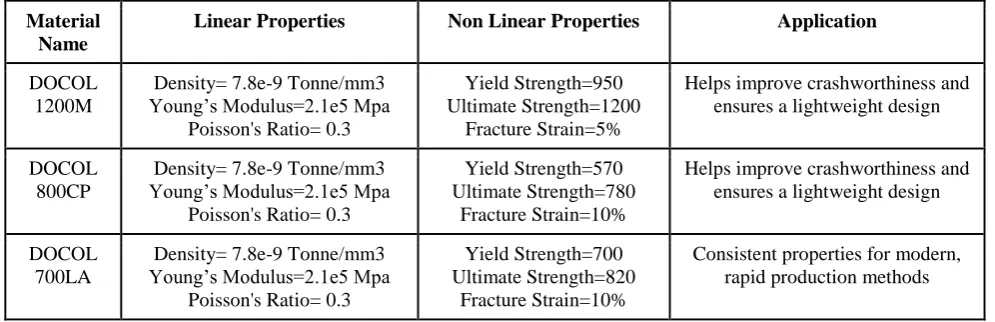
3.2 Material Details
In the chassis assembly has different material and different thickness for parts.Mainly three type of DOCOL material used in the chassis assembly, Front members are 800CP, Middle members are 1200M and rear members are 700LA.The material linear and nonlinear properties are shown in the table 3.1
Table 3.1 Material information for Chassis
Material Name
Linear Properties Non Linear Properties Application
DOCOL 1200M
Density= 7.8e-9 Tonne/mm3 Young‟s Modulus=2.1e5 Mpa
Poisson's Ratio= 0.3
Yield Strength=950 Ultimate Strength=1200
Fracture Strain=5%
Helps improve crashworthiness and ensures a lightweight design
DOCOL 800CP
Density= 7.8e-9 Tonne/mm3 Young‟s Modulus=2.1e5 Mpa
Poisson's Ratio= 0.3
Yield Strength=570 Ultimate Strength=780
Fracture Strain=10%
Helps improve crashworthiness and ensures a lightweight design
DOCOL 700LA
Density= 7.8e-9 Tonne/mm3 Young‟s Modulus=2.1e5 Mpa
Poisson's Ratio= 0.3
Yield Strength=700 Ultimate Strength=820
Fracture Strain=10%
IV.CHASSIS FEA LOAD CASES
The Chassis assembly has model in the FEA, and all sounding parts represented in the FEA.Optistruct solver is used to perform the chassis load cases, this chassis validated in the following list of load cases.
1. Modal Analysis 2. 1Gravity 3. 3Gravity
4. Bending stiffness analysis 5. Twisting stiffness analysis
6. Combination of uphill 7 degree, acceleration and cornering 7. Inertia Relief – Pot hole Analysis
8. Inertia Relief – Cornering Analysis
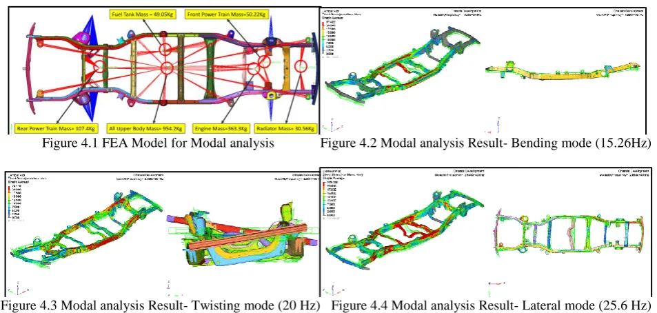
4.1. Modal Analysis
The FEA model of chassis shown in the fig 4.1 for modal analysis setup. Modal Analysis is performed to find the natural frequency of the chassis assembly to avoid the resonance with other sub-assemblies.
Figure 4.1 FEA Model for Modal analysis Figure 4.2 Modal analysis Result- Bending mode (15.26Hz)
Figure 4.3 Modal analysis Result- Twisting mode (20 Hz) Figure 4.4 Modal analysis Result- Lateral mode (25.6 Hz)
4.2 1G/3G Static Analysis
In the chassis 1 gravity (1*9.81m/sec2) load and 3 Gravity (3*9.81m/sec2) load applied and study the structural behaviour of the members with stress and displacements values. This load case will represent the vehicle at static
4.3 Bending Stiffness Analysis
Figure 4.3.1 Bending Analysis- FEA Model Figure 4.3.2 Bending Analysis- Stress-Displacement Contours
Bending Stiffness = Load/ Displacement = 6000N/3.420 = 1754.38 N/mm
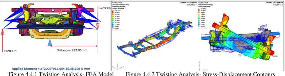
4.4 Torsional Stiffness Analysis
Figure 4.4.1 Twisting Analysis- FEA Model Figure 4.4.2 Twisting Analysis- Stress-Displacement Contours
Stiffness = Moment/ Angle of Rotation = 3000N/3.420 = 877.19N/degree
4.5 Combination Load case Analysis
Combination of 7 deg uphill, Acceleration and cornering load case on the chassis shown in the fig 4.5.1.
4.6 Inertia Relief Analysis
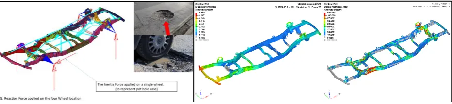
4.6.1 Pot Hole Inertia Relief Analysis
4.6.2 Cornering Inertia Relief Analysis
V. RESULTS AND SUMMARY OF ITERATIONS
S.No Load Case DV-1 DV-2 DV-3 DV-4(Final)
Stress (Mpa) Disp (mm) Stress (Mpa) Disp (mm) Stress (Mpa) Disp (mm) Stress (Mpa) Disp (mm)
1 Modal Bending = 9.1Hz
Twisting = 9.8Hz Lateral = 18HZ
Bending = 11 Hz Twisting = 12 Hz Lateral = 22 HZ
Bending = 12 Hz Twisting = 14Hz Lateral = 22 HZ
Bending = 15 Hz Twisting = 20 Hz Lateral = 25HZ
2 1G 405 5.9 213 3.7 213 3.7 80 1.26
3 3G 1218 17.8 640 11.2 639 11.2 243 3.79
4 Bending 254 16.4 164 5.7 121 4.36 103 3.4
Figure 4.6.1.1 Pot Hole Inertia Relief Analysis-
FEA
ModelFigure 4.6.1.2 Pot Hole Inertia Relief Analysis- Displacement Stress Contours
Figure 4.6.2.1 Cornering Inertia Relief Analysis- Finite Element Model
6 Combination 1667 33 934 20.11 933 20 313 3.68
7 Pot Hole 736 17.7 438 10.11 438 9.6 279 5.12
8 Cornering 731 23.1 452 13.46 450 12.6 514 8.32
10 Mass 1.83 Tonne 1.88 Tonne 1.89 Tonne 1.857 Tonne
VI.CONCLUSION FUTURE SCOPE OF WORK
In the current research on chassis development has concluded with following information,
• The performance of the design version 1 (3mm) single C section frame chassis is very low in all load cases, and the twisted load case is the worst case of DV1.
• The design version 2 (5mm) single C section frame chassis load case performed better than the DV1, but this performance is not enough for this SUV.
• Design version 3 (5mm) single C section with reinforced frame, chassis load case performance is almost the same as DV2, so performance will not improve much.
• Design version 4 (various thickness 2.6-3.8mm) double C section frame chassis load case performance is very good, stress and displacement values are greatly reduced.
Therefore, this DV4 chassis works well in all chassis load cases, Also this chassis need to perform well in crash load cases. It must deform and absorb more crash energy in order to increase the occupant safety.
The future scope of this research is Fatigue, durability, Vibration analysis and crash Analysis for DV4 Chassis.
REFERENCES
[1] Nitin S. Gokhale. (2008). “Practical Finite Element Analysis”. Finite To Infinite. ISBN: 8190619500 [2] Julian Happian-Smith (2001). “An Introduction to Modern Vehicle Design” Elsevier ISBN: 0750650443
[3] Cicek Karaoglu, N. Sefa Kuralay (2001) „Stress analysis of a truck chassis with riveted joints‟. Elsevier: Finite Elements in Analysis and Design V.38 (2002) 1115–1130
[4] H.J. Beermann, (1989) “The Analysis of Commercial Vehicle Structures”, Mechanical Engineering Publication Limited, Vol.5 PP. 28-46. [5] Kallappa Khannukar (2015) „Dynamic Analysis of Automotive Chassis using FEA‟ IRJET. Vol: 02 Issue: 09.
[6] Monika S.Agrawal (2015) „Finite Element Analysis of Truck Chassis Frame‟ IRJET. Vol: 02 Issue: 03 [7] Rajappan.R (2013) „Static and Modal Analysis of Chassis by Using FEA‟ Ijes. Vol: 02. Issue: 02 PP: 63-73.