Study on Cold Formed Steel Sigma Sections
and the Effect of Stiffeners
Anna Green Antony1
P.G. Student, Department Civil Engineering, SCMS School of Engineering and Technology, Ernakulam, Kerala,
India1
ABSTRACT: Cold formed steel sections are currently widely used as primary framing components and secondary structural systems. They are used as purlins and side rails or floor joist, and after that in the building envelops. The geometry can significantly influence the stability response of cold-formed steel members and their failure patterns. The section selected for the study is CFS sigma section. The behaviour of the sigma section and the effect of providing stiffeners are studied. . Providing stiffeners can influence the ultimate load of the section. In this paper, inclined and transverse stiffeners are provided at the flange and their effect on the ultimate load is studied.
KEYWORDS: CFS sigma section, stability, failure pattern, inclined stiffeners, transverse stiffeners, ultimate load
I. INTRODUCTION
Cold Formed thin steel sheet products are extensively used in building industry, and range from purlins to roof sheeting and floor decking. Generally these are available for use as basic building elements for assembly at site or as prefabricated frames or panels. These thin steel sections are cold-formed, that is their manufacturing process involves forming steel sections in a cold state from steel sheets of uniform thickness. These are called as Cold Formed Steel Sections. Sometimes they are also called light gauge steel sections or cold rolled steel sections. The thickness of steel sheet used in cold formed construction is usually 1 to 3mm. Much thicker material up to 8 mm can be formed if pre-galvanised material is not required for the particular application. The method of manufacturing is important as it differentiates these products from hot rolled steel sections. Normally, the yield strength of steel sheets used in cold-formed sections is at least 280 N/mm2, although there is a trend to use steels of higher strengths, and sometimes as low as 230 N/mm2. Manufacturers of cold formed steel sections purchase steel coils of 1.0 to 1.25 m width, slit them longitudinally to the correct width appropriate to the section required and then feed them into a series of roll forms. These rolls, containing male and female dies, are arranged in pairs, moving in opposite direction so that as the sheet is fed through them its shape is gradually altered to the required profile. The number of pairs of rolls depends on the complexity of the cross sectional shape and varies from 5 to 15. At the end of the rolling stage a flying shearing machine cuts the member into the desired lengths. An alternative method of forming is by press - braking which is limited to short lengths of around 6 m and for relatively simple shapes. In this process short lengths of strip are pressed between a male and a female die to fabricate one fold at a time and obtain the final required shape of the section. Cold rolling is used when large volume of long products is required and press breaking is used when small volumes of short length products are produced. Although the cold rolled products were developed during the First World War, their extensive use worldwide has grown only during the last 20 years because of their versatility and suitability for a range of lighter load bearing applications. The behaviour of CFS sigma section subjected to concentrated load is discussed in this paper.
II.RELATEDWORK
noted. A load deflection diagram was plotted. The effect of loading was the main focus of the study. Non-linear analysis was carried out. The results specified the buckling modes of the section.SudhirSastry Y B, Y Krishna andAnirudhKoduganti[2],(2014) published a paper regarding flexural buckling analysis of thin walled lipped channel cross section beams with variable geometry. This paper it is considered C cross section with variable geometry and length. The critical buckling loads have been studied for several combinations of the geometry parameters of the beam with the help of ANSYS and drawn the result plots.
III. COLD FORMED STEEL SIGMA SECTION
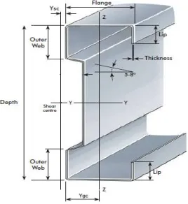
Sigma purlins are now more preferred than the conventional steel sections because of their better performance in resisting loads. These also have higher web stiffness which helps them to carry more loads. These also have shear centre close to the web. In addition these are light weight and economic.A typical sigma section is shown in Fig 1
Fig 1. Typical view of sigma section
IV.OBJECTIVES
1. To study the behaviour ,determine the load bearing capacity and failure of cold formed steel sigma section with concentrated load and boundary conditions , one end hinged and other end roller.
2. To study the effect of stiffenenrs on the load carrying capacity of CFS sigma section.
V.METHODOLOGY
1. Experimental study on CFS sigma section with concentrated load and one end hinged and other end roller boundary condition.
2. Numerical analysis of the experimental results using ANSYS .
3. Numerical analysis on the effect of stiffeners on the load carrying capacity.
VI.EXPERIMENTALSTUDY
(a) (b) (c)
Fig. 2.(a) CFS sigma dimensions (b) Universal Testing Machine (c) Test specimen
The dimensions , test setup and the procedure is shown in Fig 2. The load deflection graph was obtained from the computer and it showed a maximum load of 23 kN. Therefore the ultimate load carrying capacity of the member was found to be 23 kN.
(a) (b) Fig 3 (a) Test setup (b) Load deflection curve
The maximum deflection obtained corresponding to this load was 27 mm. Deflection of the flange started at 12 kN load and then increased upto 23 kN and then remained constant. From the load displacement diagram, it was seen that the deflection started at 12kN load. The capacity of the section gradually increased upto 16 kN and the to 23kN. For the load range from 12 kN to 16 kN , flange local buckling occurred whereas afterwards the exterior web also took part in caarying the load from the flange and hence local buckling occurred at the exterior web also.
(a) (b)
Plate elements laterally supported along edges and subjected to membrane compression or shear may buckle prematurely. Therefore, the buckling of the plate elements of the cross section under compression may take place before the overall overall beam failure by lateral buckling or yielding. This phenomenon is called local buckling. In the case of beams, the compression flange behaves as a plate element subjected to uniform compression and, depending on whether it is an outstand or an internal element, undergoes local buckling at the corresponding critical buckling stress. Local buckling has the effect of reducing the load carrying capacity of columns and beams due to the reduction in stiffness and strength of the locally buckled plate elements. Therefore it is desirable to avoid local buckling before yielding of the member. Most of the hot rolled steel sections have enough wall thickness to eliminate local buckling before yielding. However, fabricated sections and thin-walled cold-formed steel members usually experience local buckling of plate elements before the yield stress is reached. For those cross-sections liable to buckle locally, special precautions need to be taken in design. However, it should be remembered that local buckling does not always spell disaster. Local buckling involves distortion of the cross-section. There is no shift in the position of the cross-section as a whole as in global or overall buckling. In some cases, local buckling of one of the elements of the cross-section may be allowed since it does not adversely affect the performance of the member as a whole.
VII.NUMERICALANALYSIS
The modelling of the sigma section was done in ANSYS 16.2. the span of the member was taken to be 700 mm. The support conditions selected was hinged at one end and roller at the other end. Concentrated load was applied at the center of the specimen. The modelling and analysis is shown in Fig 3.
(a) (b) (c)
(d)
Fig.5 (a) CFS Sigma section model (b) Meshing (c) Boundary conditions and loading(d) Deflection diagram
VIII.STIFFENERS
Stiffeners are secondary plates or sections which are attached to beam webs or flanges to stiffen them against out of plane deformations. There are two principal types of stiffeners :Longitudinal web stiffeners, which are aligned in the span direction, Transverse stiffeners, which are aligned normal to the span direction of the beam.Stiffeners have one or both of the following functions: controlling local buckling and connecting bracing or transverse beams. Local buckling occurs when a cross section is slender enough for buckling to occur within the cross section, due either to compression or shear. The webs of bridge beams are usually vulnerable to local buckling, but flanges are usually much thicker and inherently more resistant to buckling. Local buckling can occur due to transverse compression load e.g. a web subjected to a bearing reaction, longitudinal compression load e.g. from bending, or from shear. In all cases the addition of a relatively small stiffener to a slender plate can increase the resistance to local buckling substantially. The easiest way to brace steel beams together is by fixing the bracing to transverse stiffeners. Thus stiffener positions almost always coincide with bracing positions. In a ladder deck the webs of transverse beams can be connected directly to the main beam stiffeners, so stiffener spacing matches transverse beam spacing. In a multi-girder bridge with cross bracing the bracing members are usually connected to the main beam stiffeners, so that stiffener spacing is the same as bracing spacing. Intermediate transverse web stiffeners: it is usually necessary to provide intermediate stiffeners on main beam webs for the practical purpose of connecting torsional bracing between the beams. If so, the chosen bracing positions will determine the positions of at least some of the stiffeners. However, for beams with no bracing , such as transverse girders in a ladder deck bridge, or if plan bracing is being used, there may be no practical necessity for intermediate stiffeners at all. The requirement for intermediate transverse web stiffeners is determined by the verification of the shear resistance this will indicate where stiffeners are needed, and where stiffeners extra to those for bracing are needed.Inclined web stiffeners of 1cm width was provided connecting the top flange and the exterior web. During the experimental study, the top flange was found to deflect and hence providing stiffeners for these would increase the load carrying capacity of the section.The modelling and analysis of sigma section with stiffeners in ANSYS is shown below.
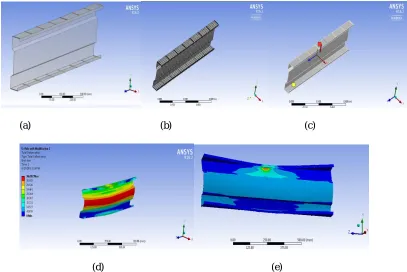
(a) (b) (c)
Fig. 6 (a) Modelling of sigma section with stiffeners in ANSYS (b) Meshing (c) Loading and boundary conditions (d) Deflection diagram (e) Stress concentration
The loading was carried out similar to that of the single sigma section. Point loading was provided and the maximum load carried by the stiffened section was found to be 48.45 kN. For the single sigma section, the maximum obtained load was 23 kN. There was an increase in 25.45 kN capacity. The capacity was increased by more than two times with a lower deflection.Transverse stiffeners of 1cm width was provided on the top flange. During the experimental study, the top flange was found to deflect and hence providing stiffeners for these was studied to find the increase in the load carrying capacity of the section.The modelling and analysis of sigma section with stiffeners in ANSYS is shown in Fig 5.
(a) (b) (c)
(d) (e)
Fig. 7 (a) Modelling of sigma section with stiffeners in ANSYS (b) Meshing (c) Loading and boundary conditions (d) Deflection diagram (e) Stress concentration
XI. CONCLUSION
CFS sigma sections were tested on a UTM with concentrated load to determine the load carrying capacity and the failure patterns for single sigma section and for different joints including back to back joint, single cleat joint and double cleat joint. The boundary conditions provided was hinged at one end and roller at other end.
Under the above said loading and boundary conditions, the CFS sigma section showed a maximum load of 23kN and a deflection of 27mm. Flange and web local buckling was observed. Numerical FEM modelling for the same was done and a deflection of 29.995mm was obtained.
sigma section. Therefore, providing inclined stiffeners to CFS sigma section increased the load carrying capacity while decrease in deflection.
REFERENCES
[1] Luis et al.,(2013) .“Experimental and numerical analysis on the structural behaviour of cold-formed steel beams”, Journal of Structural Enginnering, Vol II, pp 1-13.
[2] Hanna. M.T and Gendy .L. Bassem(2015) .”Effect of geometric imperfections on the ultimate moment capacity of cold-formed sigma-shape sections”, Housing and Building National Research Center Journal, Vol I.
[3] Vijayasimhan M, Marimuthu V, Palani G.S and Rama Mohan Rao.(2012),” Comparative Study on Distortional Buckling Strength of Cold-Formed Steel Lipped Channel Sections” , Journal of Structural Enginnering, Vol I.
[4] NadimWehbe, PouriaBahmani, And Alexander Wehbe(2013) “Behavior of Concrete/Cold Formed Steel Composite Beams: Experimental Development of a Novel Structural System” International Journal of Concrete Structures and Materials Vol.7.
[5] Brad Ford et al.,(2007).” Lateral-distortional buckling of steel I section members”, ASCE, Vol 3.
[6] SudhirSastry Y B, Y Krishna , AnirudhKoduganti.(2014) “Flexural buckling analysis of thin walled lipped channel cross section beams with variable geometry” International Journal of Innovative Research in Science, Engineering and Technology”Vol. 3, Issue 6.
[7] Chung K.F., Ho H. C. (2005), “Analysis and design of lapped connections between cold-formed steel Z sections”. Thin-Walled Structures,Vol 43, pg 1071-1090.
[8] Norbert Delatte,” Failure of Cold-Formed Steel Beams duringConcrete Placement”, ASCE,May 2005
[9] AsrafUzzaman, JamesB.P.Lim , DavidNash , JimRhodes , BenYoung,” Web crippling behaviour of cold-formed steel channel sections with offset web holes subjected to interior-two-flange loading”, Thin-Walled Structures 50 (2012), pg 76–86.
[10] AsrafUzzaman, JamesB.PLim , DavidNash , JimRhodes , BenYoung, “Cold-formed steelsectionswithwebopeningssubjectedtowebcrippling under two-flangeloadingconditions—Part II:Parametricstudyandproposed design equations” Thin-Walled Structures 56 (2012) pg79–87. [11] Cheng Yu ,Benjamin W. Schafer, “Local Buckling Tests on Cold-Formed Steel Beams”, Journal Of Structural Engineering, December 2003,
pg 1596-1606.