Geometry Stabilization & Width Control of
Body in White
Sarang S. Dumbare1, Prakash V. Waghmode2, Mayur R. Kunjir3, Prashant R. Minde4, Prof. Nilesh Jadhav5
U.G. Students (B.E), Dept. of Mechanical Engineering, Anantrao Pawar College of Engineering & Research, Pune,
India1,2,3,4
Asst. Professor, Anantrao Pawar College of Engineering & Research, Pune, India5
ABSTRACT:In this project a fixtures of body in white has to be modified for geometry stabilization and width control of car body. This fixture helps us in reducing number of body defect and width dimensions variation which were previously occurred in old fixtures regularly because of line issues in manufacturing cars. Presently have in current condition independent corrections for models cannot be ensured and for multi model production all positions are maintained at best compromised position. To resolve this issue we are modifying fixture from which we can easily do correction in any models. In this project our focus is to reduce deviation found in fixture and to bring all PMP's within tolerance and start production for cars on modified fixture.
KEYWORDS:Body In White, Fixture, Tooling Holes, Function Mass, PMP
I. INTRODUCTION
In most of manufacturing processes, the product should be fixed securely and accurately in front of the machine in order to desire task can be accomplished. This fixing duty is the main role of fixtures in the industry. Fixture designing is an inevitable common task of both design and process planning engineers and demands considerable work, time, energy, and money. Traditional disciplines suggest the order of part design, fixture design, and then going down to manufacture planning procedure; which means that in work holding problem‘, the part, and not the process is the primary consideration. However, this method is under serious debate recently due to variety of products and need for accurate process planning far in advance. This report will describe the need for opening a new horizon in this topic.
II. SCOPE OF PAPER
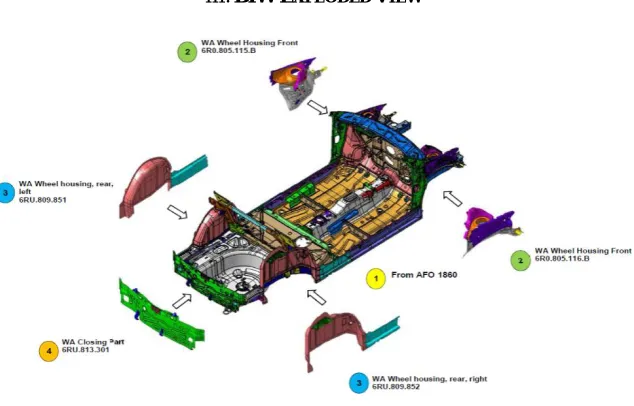
III. BIW EXPLODED VIEW
Fig 1- BIW Exploded View
The above figure shows the schematic diagram of the Body In White. As shown in the figure there are different parts of the BIW which are welded together to make complete BIW. The complete BIW consist of the different parts such as front floor, rear floor, front wheel housing LH & RH, rear wheel housing LH & RH, closure part, side sill, tunnel, seat mounting bracket, dash cowl, front long member, rear long member, seat supporting bracket etc.
IV.PROBLEM STATEMENT
In the body assembly process there are several problem could happen. When this happen it could stuck the process in assembly line and disturb certain department. While building Body in white, engineers face problems with process, single part and equipment related issues. Due to such issues, deviations are found on some important mounting brackets of BIW in measurement reports. These deviations and variations leads to defective fitment and further rework. To eliminate such fitment issues, rework and to build BIW with stable geometry, we will work together with PH team on above mentioned issues.
Due to such issues the fitment of further part is affected which leads to rework and increased process time. Due to such problem the all production line work is hampered. The problem which occurs due to such deviations are as follows- Width of the car is varying
Rear bumper fitment is NOT OK Scuff plate fitment issue
Increases rework time for better fitment of parts
Increases the cycle time for the fitment operations in assembly shop Reduces the efficiency of the production cycle
V. OBJECTIVE AND PAPER AIM
The aim of this project is to reduce the problem occurs during body assembly process and decrease the possibility that mistake could happen during work. The aim can be achieve by objective further:
Identify the problem that always happen in line assembly Improve the problem in line assembly
Make a comparison and find a solution in line assembly
Installation of Pneumatic actuator for preventing hanging of rear floor of car Installation of new myllers for supporting the underbody of vehicle
Reinstallation of the locating pins at accurate position Repositioning of RPS plane
By applying these possible solution the measurement is to be done for rechecking the dimensional stability of the vehicles and the width of the car. The measure issue that has to be overcome is to acquire a width within the tolerance limits which will help to reduce the extra rework and will produce a proper fitment of further part. Due to this increased width the rear bumper of car is not being fitted accurately, it needs to be done some hammer work on car body so that it can be well fitted at proper position. This hammering work induces some internal stresses in the part which being fitted on the car body which leads to failure of part in future when subjected to worse conditions. To avoid such problem improvement in fixture position is needed as well as the necessary changes and addition of the part is needed. For that purpose overall study of fixture and fixture design is to be analysed and modified fixture is to be developed for the production line of automobile car body. So necessary information about fixture is have to be collected from the start of the installation of fixture to the final installation of overall fixture. The study of fixture is illustrated further.
VI.MEANING OF LOCATION
The location refers to the establishment of a desired relationship between the workpiece and the jigs or fixture correctness of location directly influences the accuracy of the finished product. The jigs and fixtures are desired so that all undesirable movements of the workpiece can be restricted. Determination of the locating points and clamping of the workpiece serve to restrict movements of the component in any direction, while setting it in a particular pre-decided position relative to the jig. Before deciding the locating points it is advisable to find out the all possible degrees of freedom of the workpiece. Then some of the degrees of freedom or all of them are restrained by making suitable arrangements. These arrangements are called locators.
VII. PRINCIPLES OF LOCATIONS
This figure shows the top view of the fixture having 3-2-1 principle. As seen in figure the RPS 1 is locked in three direction whereas the second RPS i.e. RPS 2 is locked in the two direction and the third RPS i.e. RPS 3 is locked in only 1 direction. The detailed diagram of the 3-2-1 principle is given below.
Asshown in above figure the fixture is installed using 3-2-1 principle which is shown in above two figures. As seen in figure the first point is restricted in three directions i.e. X, Y & Z. The second point is restricted in two direction i.e. X & Y. And the third point is restricted only in one direction due to which this system of defining degrees of freedom is called 3-2-1 principle.
Fig-2 Car RPSSystem
VIII. CAR COORDINATE SYSTEM
Fig-4 Car Coordinate System
The above schematic figure shows the basic car geometry system used widely to specify the position of parts which is to be assembled to the car body. From the first part of the production line this coordinate system is used to specify its position. According to the CAD data some references are specified to the car body on the basis of which each and every part of the car body is assembled respectively.
The fixture position is also defined with reference of these coordinate system. The fixture is installed on the basis of these reference point defined by CAD data according to which the fixture base plate and the accessories are installed. Each and every parts measurement is done with reference to this coordinate system. The deviation in the assembly of car body and the components is shown with respect to these coordinates. An individual part measurement is also done with respect to these coordinate system. Accuracy of the BIW is also defined by the final measurement report which are based on these coordinate system.
IX.METHODOLOGY
a. position of fixture with reference to Tooling Holes
Every fixture having Tooling Holes located on its base plate which is the first part of the fixture on which fixture is to be installed. The position of all the parts of the fixture is measured with reference to these tooling holes. These positions are defined with the help of FARO arm which gives the coordinates of the point which is to be measured. All the data of the fixture measurement report is compared with the design data and made corrected as per the design data if deviations or wrong position is found.
b. Installation of fixture using FARO Arm
FARO is the market leader in portable computer-aided measurement systems. The Faro Arm enables highly precise 3D measurements of both large and small parts while in production. With three models offering 6 or 7 axes of rotation, the Faro Arm is as accurate as large, expensive fixed-bed coordinate measuring machines (CMMs), but it is portable and much easier to use. These are just some of the reasons why the Faro Arm is the world’s best-selling measurement arm. Handheld laser scanners provide a quick and effective way to inspect and reverse engineer complex parts and surfaces. They turn everyday objects into digital computer models. Soft, deformable, and complex shapes can be easily inspected – all without ever coming in contact with the part. Depending on your specific requirements, we provide the best solution for a wide range of applications across all industries. The FARO Scan Arm is the ideal tool for inspection, point cloud-to-CAD comparison, rapid prototyping, reverse engineering, and 3D modelling. In combination with the all-in-one metrology software CAM2 Measure 10, FARO Scan Arm pro videos companies with a complete metrology package for both contact and non-contact measurement.
Fig-6 Actual Measurement Of Part Using Faro Arm
a. Constrained fixture position as per CAD data design
The CNC operator finds the fixture offset values by jogging (moving) the machine from the machine at its home position the CNC program datum. This can be any point on the part, stock, or fixture, as long as it can be found by mechanical means such as an edge finder or part probe. The incremental X and Y distances moved between points is recorded and entered into a Fixture Offset Register on the CNC control. Think of the Offset registers like a table in a spreadsheet. The CNC control references these values in the table each time a motion is commanded, adding orsubtracting them from coordinates in the CNC program.
X. SPOT PLAN
When deciding how to perform a spot or stud welding operation in a line of manual stations there exist many possible alternatives since the operation can be done by more than one manual station and with many welding gun configurations. Furthermore, if several station share the same workspace then their welding spot plan need to be arranged in order to guarantee that no over weld can occur. In this WP the focus has been to develop and implement mathematical algorithms within path planning and discrete combinatorial optimization. In particular, the deliverables includes, new smoothing algorithm for manual station, improvements and generalization of the load balancing algorithm and a strategy for simultaneously balance between interlocking losses and sequence losses to optimize the final cycle time.
Spot welds are the dominant joining method in the automotive assembly process. As the automated assembly process is not perfect, some spot welds may be absent when the vehicle leaves the assembly line. Furthermore, spot welds are highly susceptible to fatigue, so that a substantial number may fail during the vehicle lifetime. It has been argued that a substantial number of spot welds may be absent in an operational vehicle, because of manufacturing inaccuracies, fatigue failures and perhaps minor accidents. Moreover, some spot welds may be forgotten in the CAD models, so that spot welds may be absent in derived CAE models as well. To take these effects into account, file management tools have been presented that allow breaking a subset of spot welds in the nominal (undamaged) vehicle model. Selection of broken
Welds can be done with uniform selection probability, or with an integer-weighted uniform selection probability.
XI.PART WELDING SEQUENCE
In the body shop the parts are welded together by means of spot welding. The single parts are first directly taken from GE-STAMP (Press Parts Vendor) which are manufactured on the basis of design given by the company. After the complete manufacturing of the parts they are compared with the CAD design with the help of measurement with the help of CMM and GOM. After verification the parts are supplied to the body shop to produce different assemblies like underbody, car body, side panels, closures and all other hang on parts.
Producing of parts as per the designed sequence is the most important factor for build the car in its proper dimension and with proper geometry. Change in the process or change in the spot sequence may leads to the improper part building and the parts which build with wrong spot sequence may be get deviated out of the tolerance as per design. The parts of the front floor are welded on different fixture.
XII. CAUSES OF PROBLEM
After verifying the dimensions with conventional dimension it is seen that there are few causes which influence the stabilization of the geometry and the assembly front floor. The causes due to which the dimension were not in tolerance limit is listed below-
i. Improper spot sequence ii. Improper material handling iii. Improper assembly storage iv. Improper methods of welding
v. Clamping and de-clamping defects vi. Single part defects
vii. Welding without clamping viii. Absence of required supports
i. Improper spot sequence
.
The spot sequence is the factor which has somewhat influence in dimension deviation. So that there are chances of variation of dimension due to improper spot sequence. As the spot is done on BIW due to wrong sequence there are chances of folding of body which is not desired, so the spot sequence should be proper so as to give dimensional stability.ii. Improper material handling
Improper material handling is the measure contributor for the changing width of BIW. Improper material handling includes many factors such as-
Improper loading and unloading of parts Improper tackling
Wrong method to pass part from fixture to fixture
Improper loading and unloading of parts
while loading the parts on the fixture sometimes the part may get stuck into the fixture RPS pins or in the locating pins then workers press them from top side or apply uneven load on the part which partially bends the part due to which the width of the part get affected which impress the effect on the front floor panels. This type of loading is not required so as to minimize the deviation in the dimensions. As well as when the part is unloaded from the fixture when it get stuck into the fixture pins then workers pull it up forcefully which affects the dimension of the BIW or front floor assembly. So this is also measure influence which affects the width of the front floor.
Improper tackling
One more cause of width change is the tackling of the floor assembly. The tackle used to lift the floor assembly but the side inserts which are inserted in the holes of the seat cross member is very nearer to the centre of the floor assembly. Due to which the side panels are subjected to the gravitation force which causes to lower down the side sill part assembly and the tunnel assembly get lifted up. Due to the plasticity of the material it does not come back to its original position even after tackle is removed or part is placed on fixture. This causes the upper side of side sill get moved to outside and bottom side get moved inside which gives the maximum front floor width from top and minimum front floor width from bottom. This is also measure issue which drastically changes the width of the front floor.
Wrong method to pass part from fixture to fixture
The improper method of passing the parts to the next fixture for further operation. The part on which complete operation was done is have to be passed to the next fixture with proper handling but the way workers adopted is kind of different. Workers directly put the part on the floor and push them towards the next fixture which causes the bending of part as well as damaged part is being assembled. This affects the side sill position which get displaced from its mean position and further it gives variation in the BIW geometry.
iii. Improper Storage Of Parts
After the assembly of the parts they should be placed properly in the storage devices or racks. The workers build the number of assemblies in working hour because they are target oriented due to which they build the assembly more than requirement due to which the storage problem occurs. If there is no enough devices to store the parts workers keep them on floor and put them one another over which apply total load of the all assemblies over the last assembly which causes maximum deformation of part and induces maximum stresses in it. Due to this the width of the part get increased and geometry get disturbed.This type of storage of parts induces the dimensional variation in the assembly which further gives improper fitment of the parts. So as to avoid this the proper part storage device should be given so that errors in dimensions due to the storage methods get reduced.
iv. Improper Methods Of Welding
stuck due to the geometry of the assembly of the front floor which causes deformation of the part due to the shock or impact of the gun probes which causes some displacement of the part of the assembly. when the spot welds get completed then worker pulls the gin outside during which the side sill part get stuck into the gun probes which pulls the side sill particular area of stuck outside. If this area is the measurement point of measurement system then it will show the maximum deviation than actual which reduces the part fitment of the further parts which should be avoided. This defects in the parts is totally depend on the methods which worker adopts for the welding. This is not constant for the all the front floors but occurs intermittently due to the improper handling of gun. If the defected part is given to measurement then it will show the maximum deviation for the parts which should be corrected.
v. Clamping And De-clamping Defects
When the part is loaded on the fixture then first step is to lock the part with the help of clamps. When part is loaded on the fixture then it clamped with the help of pneumatic pressure which holds the part under pressure until the operation is done on it. After welding the parts they are de clamped. During de clamping the clamp sometimes stuck in the parts of the body mainly in the side sill of the body which pulls it out from backward. Due to this side sill get pulled outside from top side and get moved inside from bottom side. Due to this effect the width of the car from top side get increased and from bottom side it get reduced due to which it looks like somewhat v shape. This greatly affects the width of the front floor of the BIW. So this type of the clamps should be corrected or replaced so that the defects in the width of the BIW will decrease.
vi. Single Part Defects
The single part defects are also the measure contributor for the variation in the width of the BIW. When the single parts are manufactured then due to some process variation or the wrong design of the part make it dimensionally unstable which increases the chances of variation in the dimension of the front floor assembly. If this part is having the variation in the dimension then the front floor which is going to be assembled after the part welding will not be in tolerance limit. This will not allow the further parts to be assembled correctly because of its intolerance in dimension.
vii. Welding Without Clamping
When the welding is to be done on the assembly of the BIW then some spot are difficult to weld which has to be weld after the de clamping. When these spot is to be done on the floor then welder unclamp the clamps and starts spot welding without clamping. This type of process induces improper balancing of welding forces on the part which may deflect the part position from its mean position which is not desired. Because of this there are chances of failure of spot weld as well as during welding part get displaced continuously which hampers the dimension of the front floor. Also due free movement the part deflects continuously which causes wear of the part. When the spot is done on the side sill without clamp then the side sill get moved outside due to the excessive pressure of the gun. This defects are due to the improper sequence of spot welding and the improper method of welding.
viii. Absence Of Required Supports
So due the self-weight of the front floor it slightly moves down due to the absence of the required support. When the body is loaded on the fixture then it get moved down and when the spot welding operation is going on then also the excessive pressure of the gun push the floor to the down side. This gives slight curvature to the floor assembly which increases its width from top and decreases its width from bottom. This increases the chances of misalignment between part fittings.
XIII. SOLUTION
built from sheet metal parts that have different shapes, sizes, thicknesses. Depending on their functions the parts are categorized as structural or non-structural. Structural part supports automotive body structure as main parts, for e.g. reinforcement part. The other parts are called non-structural parts for e.g. doors, roof. Based on the research it is concluded that structural parts have much greater impact on automotive body due to their greater rigidity.
The solutions after analysing the root cause are prepared and adopted which are as follows- i. Following proper spot sequence
ii. Proper material handling and part handling iii. Proper assembly and part storage
iv. Proper adoption of welding methods and follow standard work instructions and procedures v. Proper clamping and de-clamping sequence
vi. Eliminating single part defects by correcting at the initial stage vii. Addition of required supports to part while loading in fixture viii. Modification in the part lifting tackle
ix. If possible then modify the long parts by providing ribs
These are the provided solution for the stabilization of the geometry of the BIW which are adopted and implemented for the single front floor assembly for the verification purpose. These solution are applied to the single BIW for determining the effectiveness of the solutions. These solutions are applied one by one in the present system and the results after implementing the system is collected to analyse the obtained data with the previous results of the BIW and to compare the results of the same. The solutions contains the preparation as given further.
i. Following proper spot sequence
Spot welds are the dominant joining method in the automotive assembly process. As the automated assembly process is not perfect, some spot welds may be absent when the vehicle leaves the assembly line. Furthermore, spot welds are highly susceptible to fatigue, so that a substantial number may fail during the vehicle lifetime. It has been argued that a substantial number of spot welds may be absent in an operational vehicle, because of manufacturing inaccuracies, fatigue failures and perhaps minor accidents.
So as discussed earlier the spot sequence influence the dimensions of the BIW so the spot sequence is followed properly and spot numbers are also defined properly. By adopting proper spot sequence BIW is assembled and given for the further operations.
ii. Proper material handling and part handling
BIW refers to the stage in automotive design or automobile manufacturing in which the car body sheet metal (including doors, hoods, and side closers) has been assembled or designed but before the components (chassis, motor) and trim (seats, electronics items etc.) have been added. All activities in the production of a vehicle body before it goes to the paint shop are done in a body shop. The equipment used in the automotive industry has to meet the requirements related to the part’s weight and dimensions but also to the high production rates and high precision.
Proper part handling in the case of BIW part manufacturing implies that the part from the previous station should be kept proper to the next welding station without deformation and without disturbing the geometry. For that purpose the part should be lift properly by giving the necessary support and by using the proper lifting tackle.
iii. Proper assembly and part storage
iv. Proper adoption of welding methods and follow standard work instructions and procedures
While welding the parts by welding gun the necessary precautions should be taken by the team members themselves. While welding operation is going on the gun should be held at the proper location and in proper angle. It will reduce the excessive stresses in the part geometry and results in minimum distortion in the part. It will only possible when all the team members having the proper training of the welding processes and methods.
v. Proper clamping and de-clamping sequence
When the sub-assemblies are loaded on the fixture it should be held together with the help of clamps. It is not mean only clamp the part but also clamping in the proper clamping sequence. So that if proper clamping and de-clamping sequences are adopted then it assures proper engagement of sub-assemblies and ensure the minimum distortions in the parts.
Another important factor in the clamping is that fixture must having the interlocking system in the PLC so that unless and until part does not clamp, welding should not be started.
vi. Eliminating single part defects by correcting at the initial stage
All the single parts must be measured before starting to use in the daily production. It means one should have the all single part reports of each parts at the first stage of the production. The reports will be help to understand the exact root causes for the deformation of the final assemblies.
If any single part having the defects at the initial stage it will lead the deviation in the final output or final geometry. So that it will be preferable to correct the deviated single parts at the initial stages. It helps to reduce the deviation and distortion of the final assembly.
vii. Addition of required supports to part while loading in fixture
As the length of the both BIW assembled on the fixture is different due to which the extended portion of the parts remains unsupported which bends the half of the geometry towards the backside. So it is necessary to add the supports to the geometry in the fixture so that the parts will not be distorted so as the final geometry.
It is necessary to provide extra supports to the overhang parts in the fixture so it will ensure proper support and reduces chances of deformation.
viii. Modification in the part lifting tackle
While moving the assembly from previous station to the next workstation the lifting tackle is used. While lifting the part tackle is used by providing only two point contact at the centre only and it will leads to develop the stresses and deformations.
To avoid these stress development in the assembly it is necessary to design a tackle in such a way that it will lift the assembly equally and will develop minimum stresses in it. The tackle should have to use maximum number of inserts so that it will lift the body equally.
ix. If possible then modify the long parts by providing ribs
While performing operations on the long parts, the part gets bended or buckled due to their long length, which will also lead to deviation in the part. So it becomes necessary to modify the long parts by providing ribs if possible. Ribs provides alignment in mating parts or provides stopping surfaces for assemblies.
XIV.
F
UTURES
COPEAs discussed above the problem and solution of this project, the modification of the fixture and new techniques for the working has to be implemented for the better result. After the completion of this project various issues related to BIW geometry will be analysed on next geo station and the working techniques for the remaining deviation in the BIW geometry.
In future if any changes is to be done regarding dimensional instability then the with reference to this methods adopted in this project it can be done easily. It can reduce many of the concern i.e. mismatch, gap issue, part fitment etc.
REFERENCES
1. Shirinzadeh,“Flexible Fixturing for Workpiece Positioning and Constraining”.B. 2, sl. Emerald Group Publishing Limited, 2002, Assembly Automation, Vol. 22, pp. 112-120.
2. Wu, Yuguang, Gao, Shuming and Chen, Zichen. “Automated Modular Fixture Planning Based on Linkage Mechanism Theory”.s.l. : Elsevier Ltd., 2008, Robotics and Computer-Integrated Manufacturing, Vol. 24, pp. 38–49.
3. Yongkang Ma, Hui Li. Harbin, “Simulation and Optimizing of Work-station of Body-in-White Welding Based on RobCAD”,China :IEEE, 2007. International Conference on Mechatronics and Automation.
4. “Development of a Fixture for Robotic Assembly Station for an Automotive BIW (Body in White) Line”, International Journal of Advanced Mechanical Engineering. ISSN 2250-3234 Volume 4, Number 4 (2014), pp. 471-476.
5. M.P.MALI & K.H.INAMDAR, “Effect Of Spot Weld Position Variation On Quality Of Automobile Sheet Metal Parts”, International Journal of Applied Research in Mechanical Engineering (IJARME) ISSN: 2231 –5950, Vol-2, Iss-2, 2012.
6. ShaileshS.Pachbhai, LaukikP.Raut, “A Review on Design of Fixtures”, International Journal of Engineering Research and General Science Volume 2, Issue 2, Feb-Mar 2014 ISSN 2091-2730.
7. Ali Keyvani, “Modular Fixture Design for BIW Lines Using Process Simulate”, University West, Department of Technology, Mathematics and Computer Science, S-461 86 Trollhättan, SWEDEN, June 16, 2008, 2008: ROB03.
8. AravinthanArumugam and Abdul A Baharuddin, “Effect of Force Control during Spot Welding on Weld Properties”, , International Journal of Scientific and Research Publications, Volume 4, Issue 8, August 2014 1 ISSN 2250-3153.
9. Prof. Dr.-Ing M. F. Zäh, Dipl.-Ing. U. K. Munzert, Dipl.-Ing. F. Oefele, “Offline Concept For Optimization Of Robot Paths For Remote Laser Welding Without Scanners”, 10th International Research/Expert Conference “Trends in the Development of Machinery and Associated Technology” TMT 2006, Barcelona-Lloret de Mar, Spain, 11-15 September, 2006.
10. Andr_asKov_acs, “Integrated Task Sequencing and Path Planning for Robotic Remote Laser Welding”, International Journal of Production Research ijpr 2014, May 26, 2015.
11. Tatsuo Kuboshima, Tadashi Iwase, Seiji Ishizuka,“Car Body Weight Reduction With Changing Section Shapes Of Rib Structure”, MSC software vpd conference, Huntington Beach, California, July 17-19 2006.
12. Sciyo, Dr.TauseefAized,“Materials handling in flexible manufacturing systems”, ISBN 978-953-307-128-2 Hard cover, 268 pages, 17, August, 2010.
13. Prof. (Dr)V.V.Sople, ITM Business School, Navi Mumbai,“Material Handling Equipment: Exploiting Productivity Potential in Supply Chain”, Article published in 'SEARCH', Issue Vol 10, No.10, October 2007.