18th International Conference on Structural Mechanics in Reactor Technology (SMiRT 18) Beijing, China, August 7-12, 2005 SMiRT18-G10-4
PREDICTION OF FAILURE DUE TO CRACK COALESCENCE IN STEAM
GENERATOR TUBES
Abdalla Elbella
Jeries Abou Hanna
Suman Kumar Renukunta
Bradley University
Bradley University
Student, Bradley University
Peoria, IL 61625, USA
Peoria, IL 61625, USA
Peoria, IL 61625, USA
Ph: (309)-677-2718
Ph :( 309)-677-2725
Ph: (309)-370-7788
[email protected]
[email protected]
[email protected]
Keywords:Steam generator tubes, stress intensity factor, coalescence pressure, line spring elements
ABSTRACT
This paper investigates the failure mode of steam generator tubes under internal pressure in the presence of different cracks and ligament (between cracks) configurations. Leak and rupture for single crack configuration in tubes are well documented in the literature. However, when the cracks interact, the tube pressure under which the ligament between cracks fails would be different than the critical burst pressure for a tube with an individual equivalent crack. This failure pressure is termed the “coalescence pressure”. The burst pressure is the pressure at which the cracks get ruptured. The ligament failure is caused by local instability of the axial or circumferential ligaments. The coalescence pressure increases as the ligament length increases.
In this study, the fracture mechanics approach is used to investigate crack coalescence. The stress intensity factor along the crack front is used to determine the coalescence (failure of the ligament between cracks) pressure. The fracture mechanics parameters (J-integral and stress Intensity factor, KI) are determined using finite element simulation by introducing Elastic and Elastic-Plastic Line spring elements along the crack. The fracture parameters are found for different pressures and different ligament lengths and configurations. This is an inexpensive way to determine J and consequently KI. These parameters are compared with the material toughness properties JIC and KIC to asses failure and find the coalescence pressure. The results are presented for part-through wall (crack depth of 90% of tube thickness) under different pressure loadings. These results are compared with the coalescence pressure values presented in the literature using strength-based failure approach.
1. INTRODUCTION
The rupture and leak failure for the case of single cracks have been well documented in the literature (Alzheimer et al., 1979 and Cochet, B. and Flesch, B., 1987). Capabilities to predict the pressure causing failure of the ligament between any two neighboring cracks and the corresponding pressure are essential. In previous studies, Abou-Hanna et al. (2004-1) and Abou-Hanna et al. (2004-2) used nonlinear elasto-plastic finite element analysis to investigate crack coalescence of two in-line and offset cracks to establish coalescence criteria (for part-through-wall and through-wall thickness cracks). They indicated that ligament rupture starts when local instability of the ligament occurs under plane strain conditions.
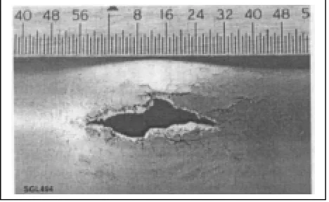
Fig.1 Failed tube from coalescence of two cracks
The thickness-pressure gradient becomes very high and the ligament is no longer capable of resisting the applied tube pressure. As a result of this local instability, the ligament thickness in the radial direction reduces gradually. Thus, the tube fails by mechanical thinning and rupture. The mechanical strength approach to design failure is used in their studies.
In this study, a fracture mechanics approach is used to investigate the crack coalescence phenomenon and predict failure. The finite element method is used to find the fracture mechanics parameters (JI and KI) along the cracks and there by predict the coalescence pressure. Failure or crack coalescence is assessed by comparing the KI and JI values predicted by finite element analysis and the material critical intensity factor or fracture toughness KIC and the JIC values, respectively. The analyses will be carried for cases of different axial and circumferential ligament lengths with varying pressure loadings. The axial ligament length here is the axial distance between the cracks and the circumferential ligament is the circumferential distance between the cracks. The results are presented for the case of part-through-wall cracks of depth of 90% of tube thickness case.
2. THE CRACK STRUCTURAL MODEL:
Table 1 The Analysis cases Matrix
Specimen Type
No. of cracks
Crack length, mm (in.)
Ligament length, mm (in.)
Type 2 2 6.35 (0.25)
0.254/1.27/2.54 (0.01/0.05/0.10)
Type 2 2 12.7 (0.50)
0.254/1.27/2.54 (0.01/0.05/0.10)
Type 2 2 25.4 (1.00)
0.254/1.27/2.54 (0.01/0.05/0.10)
Type 4 2 6.35 (0.25)
0.254/1.27/2.54 (0.01/0.05/0.10)
Figure 2 below shows a type 2, two part-through-wall cracks, which are axially offset by the ligament. PLANE 1 and PLANE 2 are symmetry planes that are to be used to generate a quarter symmetric finite element model. In type 4, two part-through cracks are circumferentially offset as shown in Fig 3.
For the Type 4 case, however, there is no model symmetry and hence the whole model is to be used for the finite element analysis.
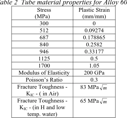
Table 2 Tube material properties for Alloy 600
Stress (MPa)
Plastic Strain (mm/mm)
300 0 512 0.09274 687 0.178865 840 0.2582 946 0.33177 1125 0.5 1700 1.05 Modulus of Elasticity 200 GPa
Poisson’s Ratio 0.3 Fracture Toughness -
KIC - ( in Air)
83 MPa m
Fracture Toughness - KIC - (in H and low
temp. water)
Axial ligament
Fig.2 Type 2 cracks with axial ligament and symmetry planes
Circumferential ligament
Fig 3 Type 4 cracks with circumferential ligament
3. THE FINITE ELEMENT MODEL
In studying type 2 cracks LS3S are used, since the model is symmetric as shown in Fig. 2. The LS6, on the other hand, are used to study type 4 cases where a finite element model of the whole cylindrical tube has to be made. Fig. 4 shows the node arrangement used to define the LS3S and LS6 elements. In the case of LS3S, only 3 symmetric nodes are used to define the elements, where as in LS6 case all the six nodes have to be used. Both these LS elements are to be used with shell elements. Since a whole finite element model is needed for LS6 elements, modeling and analyzing with them is comparatively more expensive than with LS3S element. LS6 elements meshing is, also, comparatively more involved than LS3S elements. The LS elements provide accurate results for pipes subjected to an internal pressure and having flaw depth less than 95% and more than 2% of pipe thickness (ABAQUS 6.4 Analysis User’s Manual, 2004). The outputs for LS elements are the J-integral and K values (stress intensity factors at all the integration points shown in Fig. 4).
Fig.4 Nodes used to define LS3S and LS6 line spring elements
A finite element mesh for a Type 2 case with crack and axial ligament is shown in Fig. 5. It can be seen that only a quarter model is used with symmetry considered along PLANE1 and PLANE2 of Fig.2, as stated above. For this study, many mesh density trials were carried to reach a compromise between results accuracy and run time length.
Fig.5 A quarter symmetry finite element model for Type 2 cracks
For this study, the load is simulated by a pressure applied uniformly on the inner surfaces and on the end caps of the tube. The pressure is increased until the computed JI and KI values approach the material toughness parameters JIC and KIC, respectively.
The cases that are studied in this work are as shown in Table 3. From the results obtained, it is found that only one representative case for Type 4 is necessary to show in the table.
Table 3 The study cases
Case 1 T2_250_010
Case 2 T2_250_050 Case 3 T2_250_100 Case 4 T2_500_010 Case 5 T2_500_050 Case 6 T2_500_100 Case 7 T2_1000_050 Case 8 T2_1000_200 Case 9 T4_250_010
Case Labeling
Name of the Case: TX_Y_Z
Where,
X- Crack type (if X=2 means it is a type 2 crack) Y- Length of the crack, Inch
Z- Length of the ligament, Inch
For example, T2_250_010 means a type 2 crack, with a crack length of 0.25 inch (6.35mm) and 0.01 inch (0.254mm) axial ligament. The labeling scheme was used to keep in line with the previous work of Abou-Hanna et. al. ( 2004-2).
5. RESULTS AND DISCUSSION
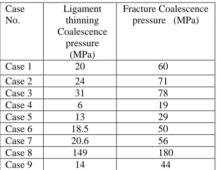
This study’s main goal is to determine if stainless steel steam generator tubes failure would take place by instabilities due to ligament thinning and hence as shown by Abou-Hanna et. al. (2004-2) or due to crack instability (fracture toughness based failure). The key outputs for the study are the computed stress intensity factors KI values, the J-integral values and the crack coalescence pressures. The coalescence (or failure) pressure here is defined as the pressure at which the computed stress intensity factor KI reaches or exceeds the tube material toughness KIC or the computed J-integral value (JI ) reaches or exceeds the tube material toughness JIC. The KI and JI values for the different cases shown in Table 3 are compared with toughness values of 65 MPa m and 335N/mm stated above, respectively. The pressures at which these toughness values are reached are considered coalescence pressures. These values are listed for the respective cases in Table 4. In column 2 of Table 4 contains the coalescence pressures reported in Abou-Hanna, J., et al. (2004-2). Column 3 of the table represents the coalescence values obtained by this study. By comparing the data in both columns, one finds that the tube failure by ligament thinning and rupture takes place very early in the loading cycle and it takes more pressure for fracture to be considered as a mode of failure. One needs to add that the toughness data used to asses the fracture mode of failure is also taken to be very conservative. The low values of 65 MPa m for KIC and 92 N/mm for JIC are for worst case scenarios.
Table 4 Comparison of coalescence pressures
Case No.
Ligament thinning Coalescence
pressure (MPa)
Fracture Coalescence pressure (MPa)
Case 1 20 60
Case 2 24 71
Case 3 31 78
Case 4 6 19
Case 5 13 29
Case 6 18.5 50 Case 7 20.6 56 Case 8 149 180
Case 9 14 44
6. CONCLUSIONS:
From this work results, the following conclusions can be derived:
1. Stainless steel alloy 600 possesses high enough toughness that fracture mode failure is not a design or operational concern. It is rather that ductile tearing failure due to rupture by ligament thinning as reported (Abou-Hanna, J., et al., 2004 - 2) should be a design concern.
2. The use of the LS elements for determining the JI and KI values along the crack prove to be both inexpensive and efficient. Caution should; however, be followed with the use of the LS6 type meshing since it is both intricate and expensive.
3. For elasto-plastic analysis, the JI values rather than the KI values should be used for assessing fracture of materials exhibiting ductility. This is true for the case of the aluminums and other metals with lower toughness.
REFERENCES:
1. Abou-Hanna, J., et al., 2004, J. Nuclear Engineering and Design, Vol. 229, pp. 175-187. 2. Abou-Hanna, J., et al., 2004, ASME IMECE, Nov. 15-17.
3. Alzheimer, J. M., et al, 1979, Steam Generator Tube Integrity Program Phase I Report, NUREG/CR-0718, PNL-2937.
4. Cochet, B., Flesch, B., 1987, Transactions of Ninth International Conference on SMiRT, Vol. D, pp. 413-419. 5. Mills, W. J. and Brown, C. M., 1999,Bettis Atomic Power Technology Report, B-T-3264.
6. Broek, D., 1986, “Elementary Engineering Fracture Mechanics”, 4Th ed., Martinus Nijhoff Publishers, Boston. 7. ABAQUS 6.4 Analysis user’s Manual,2004.