Analysis of Ring Foundation Using Finite
Element Method for Various Depth
A.N.Kamble1, Prof Dr.S.S.Patil2
P.G. Student, Department of Civil Engineering, WIT Engineering College, Ashok C howk, Solapur, India1
Associate Professor, Department of Civil Engineering, WIT Engineering College, Ashok Chowk, Solapur, India2
ABSTRACT:The ring footings are suitable and economical for symmetrical structures such as silos, cooling towers, smoke-stacks, transmission towers, radar stations, TV antennae, chimneys, bridge piers, underground stops, water towers, mine and liquid storage tanks. When compared with the other geometrical shapes of the footings, such as (strip, rectangular, square and circular footings). The ring footings enable decreasing the amount of material used and cost of construction.
Ring foundations are often adopted for large and tall structures to resist lateral loads and to increase the stability against overturning. In the design of ring foundations, very cmde simplifications have to be made. Therefore, developing a rational and practical procedure for estimating the bearing capacity of ring foundations is of great importance The effects of footing size, ring radii ratio and load eccentricity have been investigated by means of centrifuge rnodelling, the method of characteristics and the finite element technique.This study presents a series analysis of ring foundation. For analysis ten different model were used. The first of the model footings were circular; the others were ring footings. The diameters of the inner boundaries of the ring foundations for the analysis were 15.75 external dia 14.50m internal dia. The experimental studies indicate that the bearing capacity of the ring footings is depend directly on the ratio of the inside to outside radii, i.e. radius ratio.
The Finite Element Method (FEM) Its practical application often known as finite element analysis] is a numerical technique for finding approximate solution to partial differential equation (PDE) and their systems as well as integral equation. In simple terms FEM is method for dividing up a very complicated problem in to small elements that can be solved in relation to each other. The finite-element method (FEM) for a ring foundation is somewhat similar to the beam on-elastic-foundation method.
SAP2000 is a general purpose finite element program which performs the static or dynamic, linear or nonlinear analysis of structural systems. It is also a powerful design tool to design structures following AASHTO specifications, ACI and AISC building codes. These features and many more make SAP2000 the state-of-the-art in structural analysis program.
The SAP2000 graphic user interface (GUI) is used to model, analyze, design, and display the structure geometry, properties and analysis results.
KEYWORDS: Finite Element Method, Ring Foundation, Noded.
I. INTRODUCTION
Vol. 6, Issue 2, February 2017
Foundations may be broadly classified into two categories as Shallow foundations and Deep foundations. A shallow foundation transmits load to the strata at a shallower depth. A deep foundation transmits the load at considerable depth below the ground surface. The distinction between shallow and deep foundation is generally made according to Terzaghi’s criterion. According to which, a foundation is termed as shallow foundation if it is laid at a depth equal to or less than its width and if depth is greater than its width it is called as deep foundation.
For the purpose of design of foundation, the various parameters such as soil profile, depth of water table, value of density, bearing capacity, N value, coefficient of internal friction etc. are required. The choice of the type of foundation to be used in a given situation depends upon the number of factors, such as
(a) Soil strata,
(b) Bearing capacity of soil, (c) Type of structure, (d) Type of loads,
(e) Permissible differential settlement (f) Economy.
The choice is usually made from comparative study of different designs to determine the most economical foundation.
“Foundation” the main part of a building which is broadly classified into two main categories Shallow and Deep foundation. According to Terzaghi the foundation which is having its depth less than its width is Shallow Foundation and which having its depth greater than its width is Deep Foundation.
1. Shallow Foundationare Further Classified as below a) Isolated Footing
b) Combined Footing c) Mat or Raft Footing
2. Deep Foundations are Categorized as bellow a) Pile Foundation
b) Piers c) Caissons
Depending upon the nature of soil below foundation, site condition, type and amount of loading, type of super structure we have to choose appropriate foundation.
II. CONCEPTOFFINITEELEMENTMETHOD
Panel The Finite Element Method (FEM) Its practical application often known as finite element analysis is a numerical technique for finding approximate solution to partial differential equation (PDE) and their systems as well as integral equation. In simple terms FEM is method for dividing up a very complicated problem in to small elements that can be solved in relation to each other.
The FEM originated from the need for solving complex elasticity and structural analysis problem in civil engineering.
Development of the finite element method began in earnest in the middle to late 1950s for airframe and structural analysis and gathered momentum at the University of Stuttgart through the work of John Argyris and Berkeley through the work of Ray W Clough in the 1960s for use in civil engineering.
In present study Analysis of Ring foundation using finite element method will be carried out. The objective of this study is to obtain deflection, shear force, twisting moment and bending moment.
III.LITERATUREREVIEW
because of the increased hot‐spot stresses reduces the fatigue life of the structure. Also, the ultimate strength of the tubular joints is very much reduced due to the local buckling effect of the tubular members.
The finite element method (FEM) and procedures are explained, together with the application of FEM to rectangular plates, as well as circular and ring-shaped plates have been carried out by N. S. V. Kameswara Rao: 6 DEC 2010 (6)
showed the direct stiffness analysis . while beam elements, plate elements and methods of incorporating soil reaction in the soil structure interaction analysis are also presented. Bending theory is used to analyze beams and plates on elastic foundations. In addition to summarizing the finite grid method and boundary element method, a few examples of the footings using FEM are also illustrated.
IV.TYPES OF ANALYSIS
1.1 Rigid Analysis 1.2 Elastic Analysis
1.3 Simplified Elastic Analysis. 1.4 Elasto plastic Approch
V. OBJECTIVESOFPRESENTSTUDY
In the present study, RCC footings are analyzed by using Finite Element Method (FEM). The finite element model consists of subdividing the footings into small rectangular and trapezoidal solid elements. Each element has 10, 20,30,40,50,60,70,80,90 and 100 nodes. Thus, analysis of footing is done by using following elements with variable depth.
1. Rectangular element
2. Trapezoidal element
In this study are analyzed by using finite element software (SAP). In the first step of analysis ring footings is divided in to small elements in the direction of annular and width. And on that equally spaced loads are assigning and gives the different element properties rectangular and trapezoidal. In this method we discretize the footing and number of loads acting on it is constant with constant load quantity. Load is acting on the footing is a combination of live load dead load and self weight of that structure. The pressure distribution below footing is trapezoidal, with maximum pressure on one side and minimum pressure on the other side. These eccentric footings are analyzed by rectangular and trapezoidal elements and the pressure distribution and contact area of footing with the soil are studied. In all these cases, hard strata are assumed below footing which is represented in the finite element model by considering it as the fixed support.
VI.CONVERGENCESTUDYOFRINGFOUNDATION
To find out optimum model for shear force bending moment and dissplacement parametric study first of all only one parameter study is done for dissplacement by using Finite element method SAP 2000 for a ring foundation
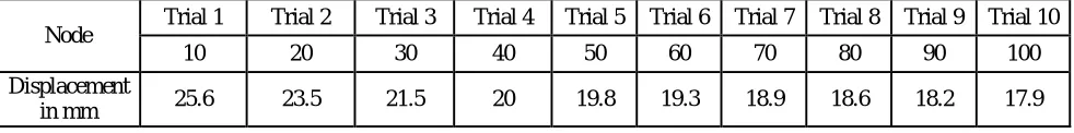
1 Result:-Trapezoidal Element
Table No.1.1 Results of Different noded Displacement of Trapezoidal element
Node Trial 1 Trial 2 Trial 3 Trial 4 Trial 5 Trial 6 Trial 7 Trial 8 Trial 9 Trial 10
10 20 30 40 50 60 70 80 90 100
Displacement
Vol. 6, Issue 2, February 2017
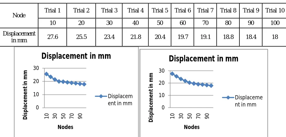
2 Result:-Rectangular Element
Table 2.1 Results of Different noded Displacement of Rectangular element
Node Trial 1 Trial 2 Trial 3 Trial 4 Trial 5 Trial 6 Trial 7 Trial 8 Trial 9 Trial 10
10 20 30 40 50 60 70 80 90 100
Displacement
in mm 27.6 25.5 23.4 21.8 20.4 19.7 19.1 18.8 18.4 18
Fig no. 1 Displacement in Trapezoidal Element Fig no.2Foundation Displacement in Rectangular Element
From above study and graph I have selected 60 Noded element as a optimum model for rectangular and trapezoidal element for further parametric study that is shear force bending moment and displacement with variable depth.
from above study it is observed that displacement of 10 noded to 50 noded is with large variations but from 50 noded element to 100 noded element displacement is with very less variation or neglegeble difference.
60 Noded element is economical in practical implementation as campared to others. From 70 noded to 100 noded result is best model is finely analysed in this but it is uneconomical for practical application but it is also better for the structure where very finely analysed result is aplicable and structures life is first priority.
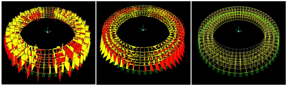
VII. PARAMETRICSTUDY
In this study foundation is descretised in 60 noded with annulary 3 parts and it have equaly spaced load is acting on it also have trapezoidal frame section.
0 10 20 30
1
0 30 50 70 90
D is p la ce m e n t in m m Nodes
Displacement in mm
Displacem ent in mm
0 10 20 30
1
0 30 50 70 90
D is p la ce m e n t in m m Nodes
Displacement in mm
Case No.1 Width = 0.76m Depth= 0.50 m
Fig d) SFD of 60 Noded Ring Foundation Fig e)BMD of 60 Noded Fig f) Displacement of 60 Noded
Case No.2 Width = 0.76m Depth= 0.75 m
Fig g)SFD of 60 Noded Ring Foundation Fig h )BMD of 60 Noded Fig i) Displacement of 60 Noded
Case No.3 Width = 0.76m Depth= 1m
Vol. 6, Issue 2, February 2017
Case No.4 Width = 0.76m Depth= 1.25 m
Fig m) SFD of 60 Noded Ring Foundation fig n) BMD of 60 Noded Fig o)Displacement of 60 Noded
Case No.5 Width = 0.76m Depth= 1.50 m
Fig p) SFD of 60 Noded Ring Foundationfig q) BMD of 60 Nodedfig r) Displacement of 60 Noded
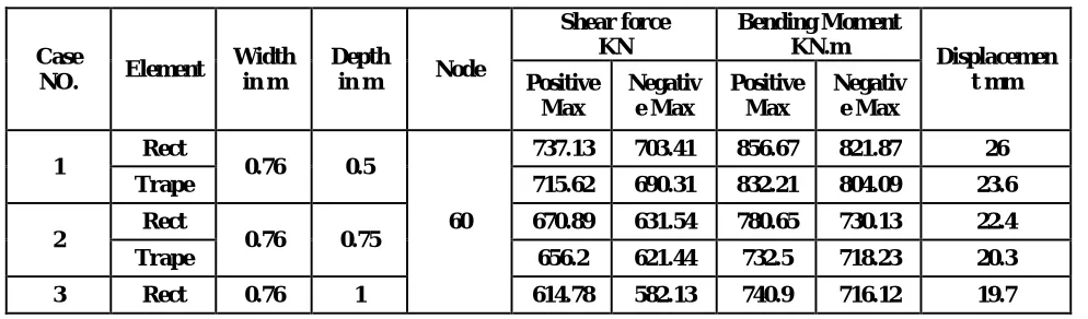
VIII. COMPARISONOFRECTANGULARANDTRAPEZOIDALELEMENT
Case
NO. Element
Width in m
Depth
in m Node
Shear force KN
Bending Moment
KN.m Displacemen
t mm Positive
Max
Negativ e Max
Positive Max
Negativ e Max
1 Rect 0.76 0.5
60
737.13 703.41 856.67 821.87 26
Trape 715.62 690.31 832.21 804.09 23.6
2 Rect 0.76 0.75 670.89 631.54 780.65 730.13 22.4
Trape 593.17 578.58 680.45 650.13 19.3
4 Rect 0.76 1.25 589.13 554.09 690 639.51 17.6
Trape 570.63 544.18 651.09 619.8 16.5
5 Rect 0.76 1.5 521.72 499.89 610.02 588.41 14.3
Trape 510.27 482.31 607.02 576.2 13.8
IX.CONCLUSION
In the parametric investigation of ring foundation by finite element method (using SAP 2000) the results are obtained for shear force, bending moment and displacement for various depth of foundation, based on these results the following conclusions are drawn:-
1. Shear force goes on reducing as the depth of foundation increasing.
2. Bending moment goes on reducing as the depth of foundation increasing.
3. Displacement goes on reducing as the depth of foundation increasing.
4. The shear force, bending moment and displacement is determined by using rectangular and trapezoidal elements variation is observed in each case are as follows,
i) The maximum positive shear force for trapezoidal element ring foundation is decreased by 1% to 3% than that of rectangular element ring foundation.
ii) The maximum negative shear force for trapezoidal element ring foundation is decreased by 2% to 3% than that of rectangular element ring foundation.
iii) The maximum positive bending moment for trapezoidal element ring foundation is decreased by 2% to 4% than that of rectangular element ring foundation.
iv) The maximum negative bending moment for trapezoidal element ring foundation is decreased by 2% to 4% than that of rectangular element ring foundation.
v) The displacement for trapezoidal element ring foundation is decreased by 4% to 8% than that of rectangular element ring foundation.
REFERENCES
1) Newmark N. M. (1942) "Influence charts for computation of stress in Beam on Elastic Foundation". University of Illinois Engineering Experiment Station bull no 338 , Urbana, IL, 28 pp
2) Moctoz M.EI-Hawary, Leonard R.Herrmann (Aug 1988) Axis symmetric Finite Element study of Elastomeric Composites. Journal of Engineering Mechanics, vol.114, no.8, pp.1355-1374.
3) M.EI Sawwaf, A.Nazir (Mar 2012) Behavior of Eccentricity Loaded Small Scale Ring Footings Resting on Reinforced Layered Soil. Journal of Geotechnical and Geo environmental engineering, vol.138, no.3.pp376-384
4) CemTopkaya, J.Michael Rotter (Dec 2011) Ring Beam Stiffness Crieterion for Column Supported Metal Silos. Journal of Engineering Mechanics, vol 137 no.12 pp846-853.
5) D.S.Ramchandra Murthy, A.G. Madhava Rao, P. Gandhi, P.K. Pant (Nov 1992) Structural Efficiency Of Internally Ring Stiffened Steel Tubular Joints.. Journal of Structural Engineering. vol.118, n0.11 pp. 3016-3035.
6) N. S. V. Kameswara Rao: (6 DEC 2010) finite element method (FEM) and procedures are explained, together with the application of FEM to rectangular plates, as well as circular and ring-shaped plates.
7) Nitesh J Singh, Mohammad Ishtiyaque(2011)Any design of Water Tanks is subjected to Dead Load + Live Load and Wind Load or Seismic Load as per IS codes of Practices.
Vol. 6, Issue 2, February 2017
9) Ahmet Demir :-The Analysis of Ring Footings using Field Test Results
10) Fletcher and Herman (Sridhar, 1999) analyzed a beam resting on flexible elastic foundation and determined the applicability of the Winkler model and more mathematically refined models which included terms involving the derivative of the deflection without resulting in any mathematical difficulty.
11) Dasgupt :-application considered an axially constrained beam resting on Winkler foundation and obtained solutions for beam using finite element method.
12) David Roylance (2001) "Finite Element Analysis" Department of Materials Science and Engineering Massachusetts Institute of Technology Cambridge, MA 02139.
13) ACI (2002) "Suggested Analysis and Design Procedures for Combined Footings and Mats", ACI Committee 336Report, 21 pp. See also the "discussion" and "closure" in the ACI Structural Journal, vol. 86, no. 1, Jan-Feb, 1989, pp.111-16.