ON THE DEVELOPMENT OF CT-TYPE SPECIMEN FROM VVER-1000
SURVEILLANCE SPECIMEN MATERIALS RECONSTRUCTION
PROCEDURE
Denis Zhurko1, Eugenia Kuleshova1, Sergey Bubyakin1, Andrey Bandura1, Artem Erak1,
1National Research Centre "Kurchatov Institute", RU, ([email protected])
A reliable evaluation of current status of reactor pressure vessel (RPV) and determination
of its lifetime necessitate receiving direct data of material fracture toughness which are used in
RPV resistance to brittle fracture calculations.
The fracture toughness data for reactors placed in commission before 2002 can be obtained
only with small-size specimens (of 10×10-mm cross-section) of SE(B)-type that are included in
VVER-1000surveillance specimens programs. The reactors placed in commission after 2002 and
all new projects of reactor plants have surveillance specimens located on internal surface of
pressure vessel in flat containers that provide for accommodation of full-scale specimens of
CT-type; the testing data for these specimens give more accurate information on fracture toughness.
This paper suggests to use test results of reconstructed specimens of CT-type made of
halve-pieces of Charpy or SE(B)-type tested specimens using electron-beam welding to enhance
of the forecast dependence of fracture toughness as compared to that obtained with SE(B)-type
specimens.
We have prepared reconstructed specimens of CT-type with insertions sized 10×10 mm
and 20×10 mm. While making welded seams, the insertion temperature was measured in the
place of anticipated fracture location. Tests and fractographic examinations were carried out to
study reconstructed and non-reconstructed specimens. The analysis have confirmed fine
precision of test results for non-reconstructed specimens of CT-type.
The fracture toughness test results for non-reconstructed and reconstructed specimens and
structural peculiarities of fractures testified that employed reconstruction procedures produce no
significant influence on the mechanisms of brittle fracture origination and characteristics of
fracture toughness specimens.
INTRODUCTION
The paper [1] suggests making the reconstituted CT specimens of the halves of tested Charpy or SE(B)-10 specimens, which are used in reactor power vessel (RPV) resistance to brittle fracture calculations, for receiving the direct data on crack resistance of VVER-1000 RPV materials.
Numerous results show that the CT specimens’ data provides more accurate measure on fracture toughness of RPV materials when compared to SE(B)-10 specimens [2, 3].
Therefore, in order to increase the level of justifying an extension of VVER-1000 pressure vessels lifetime period up to 60 years or more, the methodology for reconstitution and testing the CT specimens out of broken Charpy or SE(B) specimen fragments was developed and implemented into the surveillance specimens’ research practice.
TEST MATERIALS
The Sv-09HGNMTA-A weld metal (WM) made using the argon-arc welding had been selected as a test material. Table 1 provides the test material chemical composition.
Table 1 – Test material chemical composition
Material
Chemical composition, weight %
С Si Mn Сr Ni Mo S P Cu
WM 0,07 0,36 0,93 1,71 1,22 0,64 -* 0,007 0,04
* - N/A
SELECTION OF THE TECHNOLOGY FOR THE CT SPECIMENS RECONSTITUTION OUT OF THE CHARPY AND SE(B) SPECIMEN MATERIALS
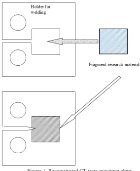
In general terms, the reconstitution process represents the welding of the vessel steel casing element on the test material’s central insert, as illustrated in Figure 1.
Figure 1. Reconstituted CT-type specimen chart
technique must provide the weld width of not more than a 3 mm heat-affected zone (HAZ); during the welding process the central insert’s temperature must not exceed the irradiation temperature for irradiated specimens under reconstitution, and must not exceed 350°C for non-irradiated specimens.
In accordance with the fragment sizes of reconstituted Charpy and SE(B) specimens, the paper [1] suggested two configuration options for welding insert with an appropriate casing configuration referring to Figure 2.
a – option 1 b – option 2
Figure 2. The layout chart for casing elements and inserts in reconstituted CT specimens with L×10×10 mm insert size: (a) – L=10 mm, (b) – L=20 mm.
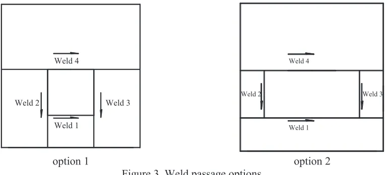
For the options suggested in Paper [1], the strain-stress state calculations in reconstituted and in standard CT-type specimens have been performed. The calculations have been conducted using the finite-element method in a physically nonlinear formulation in the ANSYS-assisted 3D elastic-plastic design. Based on the calculations, the paper proposed a weld passage sequence, as shown in Figure 3.
Weld 1 Weld 4
Weld 2 Weld 3
Weld 1 Weld 4
Weld 3 Weld 2
option 1 option 2
Figure 3. Weld passage options
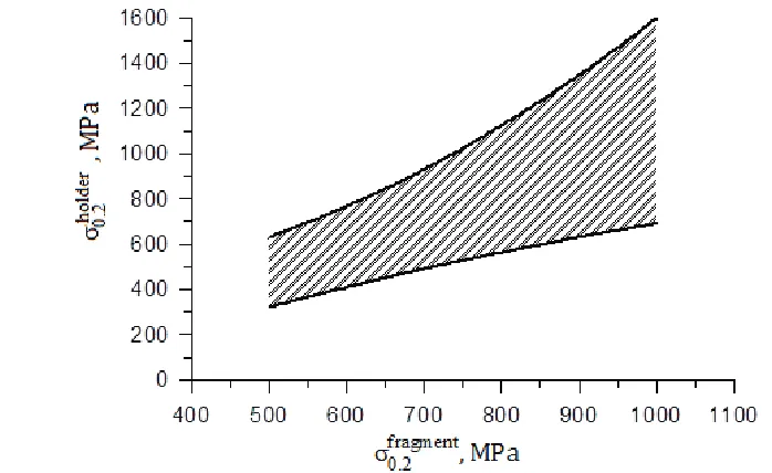
The calculations also justified the differential range of yield strength (s0.2) admissible values for
Figure 4. The range of yield strength admissible values for the casing metal, depending on the insert metal’s yield strength, when making reconstituted CT-type specimens
SELECTING THE WELDING CONDITIONS FOR CT SPECIMENS RECONSTITUTION
The reconstitution for CT specimens was performed with an electronic-beam welding system (EBS), you may see the parameters in Table 2.
Table 2 – The main EBS parameters and characteristics
Welder parameters Dimensions
Vacuum chamber internal size, mm 500/500/500
Ultimate vacuum, Pa 7×10⁻³
Beam power, kW 0÷6
Maximum beam current, mA 0÷100
Maximum weldment thickness, min, mm 20
The EBS manufacturer recommended the following welding conditions for the best weld’s quality that meets the requirements: accelerating voltage is U=40 kW, beam current is I=50 mA, welding speed is v=20 mm/s. A welded test was made on vessel steel workpieces, using an electron-erosive cutting method. The specimen was deoiled with the SBP spirit and dehydrated with ethanol prior to welding.
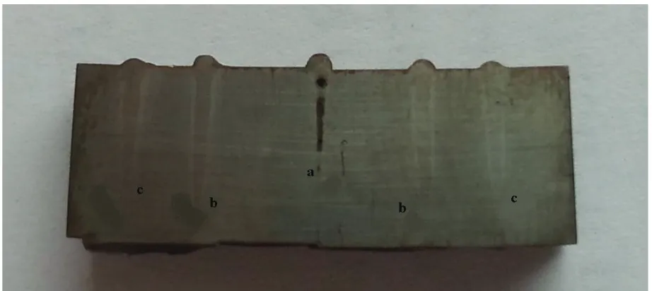
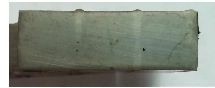
а– welding condition U=40 kW; I=50 mA. Weld’s boiling;
b – welding condition U=40 kW; I=50 mA with a surface decontamination; c – welding condition U=40 kW; I=40 mA.
Figure 5. The welded test macrosection with different EBS conditions used
После зачистки поверхности от латуни была сделана повторная сварная проба, которая показала, что сварной шов по режиму с параметрами U=40 кВ, I=50 мА проходит практически по всей толщине сварной пробы (рисунок 5, б), что недопустимо при двухсторонней сварке из-за двойной перекристаллизации. Поэтому было принято решение сделать сварные пробы по режимам с параметрами: U=40 кВ, I=40 мА (рисунок 5, в) и U=40 кВ, I=35 мА (рисунок 6, а).
Сварной шов, выполненныйпо режиму с параметрами U=40 кВ, I=40 мА, также проходит практически по всей толщине заготовки (рисунок 5, в), что недопустимо из-за двойной перекристаллизации свариваемого материала и может привести к увеличению зоны термического влияния.
На рисунке 6 представлен макрошлиф сварной пробы по режиму U=40 кВ, I=35 мА. Данный сварной шов удовлетворяет требованиям, предъявляемым к сварке. Далее была сделана сварная проба с двухсторонней сваркой (рисунок 6, б). Сварной шов получился сплошной и без видимых пор.
After removing the brass particles from the surface a retesting was conducted, and it demonstrated the weld with condition parameters U=40 kW, I=50 mA, that extends the full width of the welded test (Figure 5b), which is unacceptable in two-side welding due to the double recrystallization. So we reached a decision to make welded tests with the following condition parameters: U=40 kW; I=40 mA (Figure 5c), U=40 kW; I=35 mA (Figure 6a).
The weld completed in the following condition parameters U=40 kW, I=40 mA also extended the full width of the welded test (Figure 5c), which is unacceptable due to the weld material double recrystallization and may result in enlarging the HAZ.
a – unilateral welding; b – two-side welding.
Figure 6. Welded test macrosection performed with the EBS in the following condition parameters U=40 kW, I=35 mA, v=20 mm/s
As the result, the following welding condition was taken as a basis: U=40 kW, I=35 mA, and v=20 mm/s.
WELDING THE WORKPIECES FOR MAKING THE CT SPECIMENS AND EXPERIMENTAL TEST RESULTS ON FRACTURE TOUGHNESS
After choosing the basic welding condition the test specimens have been welded according to the schedule, shown in Figure 3.
During the welding process, the central insert’s thermometering have been taken in passing through each weld. The maximum central insert temperature value was 208°C.
After the preparatory work was complete, we settled on reconstitution of the CT specimens out of the RPV materials. Twelve standard 12.5mm thick CT-0,5 specimens and eight reconstituted 10mm thick CT-0.5 specimens with inserts sized 10×10 mm and 20×10 mm have been prepared.
Fatigue crack growth has been performed with an electromechanical resonance machine («Rumul Microtron», Switzerland) on all reconstituted and standard specimens according to [4].
Conducting the fracture toughness tests, the data processing and the construction of fracture toughness temperature dependence KJС(T) were made in accordance with [4].
Figure 7 presents the fracture toughness test results for reconstituted and standard homogenous specimens of the WM material. The reference temperature value Т0 is minus 26°С for standard specimens, minus 24°С (10×10 mm sized insert) and minus 32°С (20×10 mm sized insert) for reconstituted specimens. Therefore, the difference in temperatures received for reconstituted and standard specimens is nonsignificant. As the Figure 7 shows, the KJС values obtained with reconstituted specimens fit the scatter band of values obtained with standard CT specimens, and the reference temperature values Т0 are sufficiently close. The received close reference temperature values Т0 indicate a
-100 -80 -60 -40 -20 0 20 0 25 50 75 100 125 150 175 200 225 250 275
K Jclim(B=10 мм)
K Jclim(B=12.5 мм)
Standard samples СТ-0.5 T0=-26 °С
Reconstruction, fragment 20х10 mm T0=-32 °С Reconstruction, fragment 10х10 mm T0=-24 °С
K JC , MP a Ö m Temperature, °C
Figure 7. Standard and reconstructed CT-0.5 specimens’ test results correlation (dots – experimental value KJС, lines – dependences KJC(med)(Т) corresponding to Pf=0.5 и В=25 mm)
CONCLUSION
1. The present paper justified the EBS applicability to making the welds on reconstituted CT specimens. The welding temperature and the EBS parameters, enabling compliance with the solidness and weld width requirements, were defined.
2. The CT standard and reconstituted specimens of the Sv-09HGNMTA-A WM made using
the argon-arc welding were presented. The paper demonstrates that the maximum Т0 values difference
does not exceed 6°C, which indicates a good correlation of the experimental data for the given types of specimens.
REFERENCES
[1] Marsden, B. J. and Hall, G. N. (2012). “Graphite in Gas-cooled Reactors,” Comprehensive Nuclear Materials, Elsevier, UK.
[2] B.Margolin, V.Kostylev, V.Fomenko, D.Zhurko, S.Bubyakin, A.Bandura. Developing the methodology for reconstitution of the CT specimens out of the surveillance specimens from the VVER-1000 RPV materials. Part 1: Justifying calculations. “Voprosy Materialovedeniya” in progress.
[3] Lidbary D. et al. Recent R&D on constraint based fracture mechanics: the Vocalist and NESC – IV projects, in: Proceedings of International Seminar «Transferability of Fracture Toughness Data for Integrity of Ferritic Steel Components», November 17-18, 2004, Petten, the Netherlands, EUR 21491 EN, pp. 38-58.
[4] Margolin B. Z., Fomenko V. N., Gulenko A. G., Shvetsova V. A., Nikolaev V. А., Morozov A. M., Vakulenko A. A., Piminov V. A., Shulgan N. A. Prediction of the temperature dependence of fracture toughness for RPV materials from test results of surveillance specimens. ISSN 1994-6716 “Voprosy Materialovedeniya”, 2008, № 3(55), 111-124.