Finite Element Analysis and Optimization of Jib
Crane Boom
Chaitra C. Dandavatimath 1, Prof. H. D. Sarode 2
P.G. Student, Department of Mechanical Engineering, TSSM’s PVPIT, Bavdhan, Pune, India1
Associate Professor, Department of Mechanical Engineering, TSSM’s PVPIT, Bavdhan, Pune, India2
ABSTRACT:The study includes an investigation ofthe bending behavior of regular I section cantilever beam of jib crane subjected to self-weight and load at the free end. A new design is proposed in this study to tackle the bending and increase the strength of the crane. Finite element analysis is carried out to analyze the effect of geometrical parameters of various web shapes. The thickness of the flange is constant for all specimens with length 2.54 m and tested for 500 Kg load lifting capacity. Structural analysis is done to examine the influence of the section dimension due to load at the free end on cantilever. From FEA and subsequent analysis it is observed that changing the web designs, influences load carrying capacity and resistance to bending.
KEYWORDS:Jib Crane,Design, Finite Element Method, Analysis.
I. INTRODUCTION
A jib crane is in effect a monorail that is cantilevered from its supporting members and pivoted at one end. The horizontal beam provides the track for the hoist trolley. Jib crane have three degrees of freedom. They are vertical, radial, and rotary. However they cannot reach into corners. They are usually used where activity is localized. Lifting capacity of such cranes may vary from 0.5 ton to 200 ton and outreach from a few meters to 50 meters. Such cranes find various applications in port area, construction site and other outdoor works. For handling general cargo, lifting capacities usually 1.5 ton to 5 ton with maximum out reach of 30 meter. Jib crane provided with grabbing facilities have usually a capacity ranging from 3 ton operating 50 to 100 cycles per hour. Lifting heights may be 30 meter or more. Jib cranes used in ship yards for lifting heavy machinery equipment, weighing 100 to 300 tons, are usually mounted on pontoons. Frequently, these cranes are provided with two main hoisting winches which can be employed singly or together to lift a load. For handling light loads may hand auxiliary arrangement localized, such as in machine shops. Column mounted jib cranes are commonly used in packaging industry. The size of the crane can be visualized from the height of the operator. These cranes are used for hoisting up to 1 ton loads.
II. LITERATURE SURVEY
A. Amit.S.Chaudhary, Subin.N.Khan, “A review paper on structural analysis of cantilever beam of jib crane.”
B. Effect of Triangular Web Profile on the Shear Behaviour of Steel I-Beam - By Fatimah De’nan, MusniraMustar, Adzhar Bin Hassan and Norbaya Omar
This paper develops a three-dimensional finite element model using LUSAS 14.3 to study on the effect of the triangular steel beam web profile (T WP) in the shear buckling behaviour of different thickness compared RI to that of the normal flat beam (FW). Eigenvalue buckling analysis was used in analysing the buckling load of the flat plate model and triangular web profile (TRIWP). Results showed that the web thickness gave a significant impact on the shear buckling of the TRIWP. In addition, the corrugation thickness of the web was also effective in increasing the shear buckling capacity of the profile.
C. Gerdemeli I., K. Kurt S., Tasdemir B. “Design And Analysis With Finite Element Method Of Jib Crane.”
In this study; JIB cranes, which generally used in ship manufacturing and maintenance processes, have been analysed. Results of the analytical calculation and the results that were obtained by finite element method have been compared. In this way, it has been investigated the reliability of the finite element method for JIB crane design. As a result, it has been seen that, F.E.M is the most practical and reliable method which can be utilized during JIB crane design process. At the end of the study, results of the analytical calculation and the results that were obtained by finite element method have been compared. According to these comparison results, it has been seen that, the error margins were between the acceptable boundaries.
D. Chirag A. Vakani, Shivang S. Jani “ Analysis and Optimization of 270° Jib Crane Deflection.”
A typical jib crane consists of a top beam which is rotating around a fixed column which may be referred to as an L-shaped structure. Current material handling systems exhibit anisotropic behaviour. Movement of these devices is correspondingly difficult. Thejib crane, is selected for research into creating isotropic motion. Deflection occurs of T-section as a span of Jib crane. Analysis showed that a T-T-section will withstand large transverse deflection without in-plane ply failure; the predominant failure mechanism is delaminating in the fillet region. Especially Jib Crane used for circular material handling, it menace radial work. Through the literature review jib crane utilization where required radius type work. That is, their two planar degrees of freedom require different amounts of force input from the operator. Movement of these devices is correspondingly difficult. Fibres are elasticity Furthermore some additional load cases not contemplated in the norm have been established and they have a great interest for a correct design of the mechanical set, principally because the simulate some manoeuvres that, although they are discussed.
III. METHODOLOGY
i. Literature Survey - Using the knowledge from literature review, one can select the jib crane on which further
study can be done. Selection of crane is done as follows :
1. Selection of Crane (Phase-1) - While selecting the crane type, numbers of different factors are taken into account they are capacity, operation requirement, application, design.
2. Selection Criterion (Phase-2) - Today’s industry demands versatile, efficient equipment while at the same time providing more flexibility along with significant savings through increased productivity. A jib crane can help to improve materials handling efficiency and work flow.
Table No.1: Selected Jib Crane (FS300-8-6)Specifications. Sr. No F re e stan d in g ji b C r an e sp e c if ic at ion
Particular data Details
I-Be am S p e ci fi c at ion .
Particular data Details
M ate r ial P r op er ti e s. (S tr u c tu r al S te e l)
Particular data Details
1 Capacity ½ Ton Height, h 152.4
mm Young’s Modulus 2×10 5
MPa
2 Rotation 360º Flange Width,
b 160 mm Poisson’s Ratio 0.3
3 Support floor Web thickness,
s 6 mm Density
7.85×10⁻⁶ kg/mm
4 Height Under Boom
2438.4 mm
Flange
thickness, t 9 mm
Tensile yield
strength 250 MPa
5 Boom Length 2540 Filler Radius,
R 9 mm
Tensile Ultimate
strength 460a
ii. CAD Model Generation - Getting input data on dimensions of I-beam from research papers and Creating 3D
model in CATIA.
Figure 1 : CAD Model.
iii. Determination of loads - Study, find and apply various loads that are acting on boom. a. Capacity of crane (W) = 500 kg
b. Load acting on boom (F) = W x g = 500 x 9.81 = 4905 N in downward i.e (-Z) direction over 100mm span at free end. c. Fixed support= Mast Dia. (E) = 8’’ = 203.2 mm ~ 204 mm
iv. Testing and Analysis - Meshing the CAD model and applying the boundary conditions. Solve for the solution of meshed model using ANSYS.
Figure 3 : Von Mises stress and Displacement of for boom
v. Re-Design, Analysis and Result with design - Study various newly proposed designs.Analyze the newly proposed design model and finding out the best suited design model. Checking and ensuring it is well within the safe region.
IV. PROPOSED TOPOLOGICAL CHANGES IN WEB SECTION OF THE I-BEAM.
Original web boom’s CAD model is generated, constraints are give and then analysis is carried out to find out Von- mises stresses and deformation as described above in methodology.Similar procedure is carried out for different proposed models only topological changes have been carried out on web section of the I-Beam.
1. Proposal – 1: Triangular
Figure 6: Displacement result for boom.
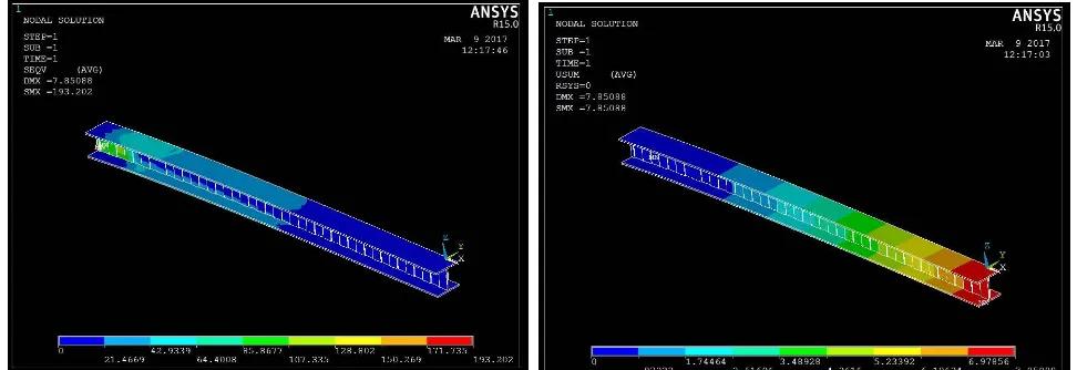
2. Proposal – 2: Trapezoidal.
Figure 7 : Trapezoidal web section Boom.
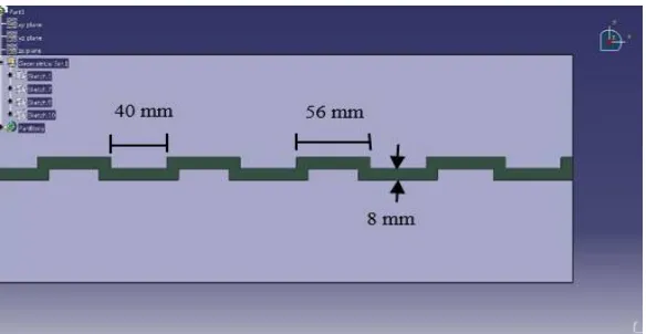
3. Proposal – 3: Rectangular 1 ( 6mm thick )
Figure 10 : Rectangular web section Boom.
Figure 11 : Von-mises stress for Boom Figure 12 : Displacement result for boom.
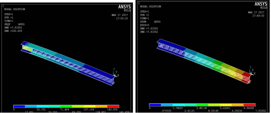
4. Proposal 4 : Rectangular 2( 8mm thick )
Figure 14 : Von-mises stress for Boom Figure 15 : Displacement result for boom.
5. Proposal 5:
Figure 16 :Proposal 5.
V. ANALYSIS RESULTS
FEM Analysis is carried out on all of the proposed design models and results show that Proposal 4 has less stress and deformation compared to all iterations.
Table 2 : Comparison Table.
VI. FUTURE SCOPE
This paper contains only the analysis results. For validation purpose one needs to manufacture the rectangular web section I-beam.A scaled down model can be manufactured and later can be tested on UTM.Following manufacturing assumptions are made :
Since it’s a scale down model, the loads that will be applied will also be proportional. The rectangular profile of web can be manufactured by milling operation.
Welding on the upper and the lower plates.
For testing, one end of the boom will be fixed to a rigid block and cantilever loading is applied on the other end as per ratio on UTM.As the load increased from zero to the design load; load vs deflection graph will be generated by data acquisition system sensed through load sensors in UTM.This deformation of the I beam which is obtained from graph can be compared with analysis results for validation purpose.
VII. CONCLUSION
A new design approach of beam shape has been proposed to reduce deformation and stresses generated due to direct loading We had scope for optimizing its topology without effecting its structural behaviour rather increasing its load bearing capacity.So we made possible topological i.e. shape changes in the web. Various web profiles have been designed for the boom ,keeping same material properties, boom length and width of I-section. After carrying out Finite element analysis on original design and 5 proposed designs, it is observed that proposed model no 4 i.e. rectangular web section design of boom is best amongst all. It shows 150.484 N/mm2 stress along with 7.81mm deformation. Thus generating 23% less stress and 5% less deformation as compared to the original web design. Therefore, one can conclude that the rectangular web design increases load carrying capacity of the boom with lesser deformation.
REFERENCES
1. Amit S. Chaudhary, Subim N. Khan, “A review paper on structural analysis of cantilever beam of jib crane”, International Journal of Engineering Research and General Science Volume 3, Issue 3, May-June, 2015
2. Fatimah De’nan, MusniraMustar, Adzhar Bin Hassan and Norbaya Omar, “Effect of Triangular Web Profile on the Shear Behaviour of Steel I-Beam, Iranica Journal of Energy & Environment 4 {(3) Geo-hazards and Civil Engineering)}: 219-222, 2013, ISSN 2079-2115
3. Gerdemeli I., K. Kurt S., Tasdemir B.“Design And Analysis With Finite Element Method Of Jib Crane”, Faculty of Mechanical Engineering IstanbulTechnical University Turkey.
4. Chirag A. Vakani, Shivang S. Jani “ Analysis and Optimization of 270° Jib Crane Deflection”, International Journal for Scientific R&D, Vol. 2, Issue 10, 2014, ISSN (online): 2321-0613.
5. Fatimah De’nan, Nor Salwani Hashim, “The effect of web corrugation angle on bending performance of triangular web profile steel beam section”, International Journal of Environmental Protection, IJEP Vol.1 No.5 2011 PP.53-56.
6. Ajinkya Karpe, Sainath Karpe, Ajaykumar Chawrai “Validation Of Use Of Fem(Ansys) For Structural Analysis Of Tower Crane Jib And Static And Dynamic Analysis Of Tower Crane Jib Using Ansys”,International Journal of Innovative Research in Advanced Engineering (IJIRAE) ISSN: 2349-2163, Volume 1 Issue 4 (May 2014).
Sr.No Design Stress (MPA) Deformation (mm) 1 Original Design 193.5 8.18
2 Proposal 1 330.297 9.76 3 Proposal 2 193.202 7.85
4 Proposal 3 186.17 8.67
5 Proposal 4 150.484 7.81