ISSN(Online) : 2319-8753 ISSN (Print) : 2347-6710
I
nternational
J
ournal of
I
nnovative
R
esearch in
S
cience,
E
ngineering and
T
echnology
(An ISO 3297: 2007 Certified Organization) Website: www.ijirset.com
Vol. 6, Issue 1, January 2017
The Effect of Adding Perforation at Air Inflow
on the Mixing and Combustion of Propane Jet
in a Simple Burner
Ayedh Alajmi1, Mansour Bin Talha2, Ibrahim Abdalla3, JasemAlotaibi1, Abdullah Shalwan 4
Assistant Professor, Department of Automotive and Marine Technology, Public Authority for Applied Education and
Training, Kuwait City, Kuwait1
Lecturer, Alkharj College of Technology, Al kharj, Saudi Arabia2
Senior Lecturer, Faculty of Technology, Department of Mechanical Engineering, De Montfort University, Leicester,
UK3
Assistant Professor, Department of Manufacturing Engineering, Public Authority for Applied Education and Training,
Kuwait City, Kuwait4
ABSTRACT: This paper explores the effect of including a perforated disk at the air inflow as a method to improve the turbulence, the mixing and the combustion phenomena. This paper uses the geometry of a conventionally used simple burner. The analysis is performed with the help of Fluent 6, ANSYS CFX. As turbulence models, Reynolds Averaged Navier-Stokes equations (RANS) are used. The combustion processes are modelled with the help of Eddy-dissipation model. The paper presents four case studies. Out of these, the two main studies were based on two meshes (course and fine, respectively). In both the case studies the effect of including perforation at the air inlet was studied. The results for both the studies were evaluated by observing three different parameters: turbulence, thermal performance, and emissions. The results show that the inclusion of a perforation at the inflow of air does not increase the turbulence intensity much compared to the case in which it is not included. It is also concluded that the addition of perforation results affects the mixing procedure. Moreover, it is found relatively lower temperature is predicted in the case that perforation is added than in the case that it is not. Lastly, the simulation results show that coarse meshes predict slightly relatively higher temperatures and emissions compared to fine meshes.
KEYWORDS: air inflow, combustion, burner, computational fluid dynamics
I. INTRODUCTION
Combustion is an important process and has many applications in both the industry and in daily life. It happens as a result of a chemical reaction between fuel and oxygen (O2).The products of this chemical reaction are carbon dioxide
(CO2, water (H2O) and heat energy. Typically, there are two common types of combustion processes: complete
combustion and incomplete combustion. In complete combustion, all of the combustible parts of a fuel are burned completely, and, as a result, CO2, O2 and water vapours are produced. Contrary to this, in an incomplete combustion
process, all the combustible parts of the fuel are not burned completely and, typically, as a result, apart from CO2, O2,
and water vapours, unburned particles such as hydroxide ion (OH-), carbon monoxide (CO) and di-hydrogen (H2)
In this paper, the combustion phenomenon, in simple burner geometry, is explored. Moreover, the outputs of the combustion of propane in two different scenarios are alsostudied. ANSYS software is used in this study. Two models are used. In this first one no air filter is included while in the second one, an air filter is used at the air inlet. The results of both the models are compared. Finally the results of both the models are presented and analysed.
The rest of this paper is organized in the following four sections. In Section II, relevant literature is reviewed. In Section III, the methodology used in this paper is presented. In Section IV, the results are presented and discussed. Finally, in Section V, conclusions are presented.
II. RELATED WORK
The design of the combustion chamber, especially its geometry, plays an important role in determining its efficiency. For example, the use of narrow and deep chambers can help reduce the amount of nitrogen oxides [3].
Liu et al. [4] study the optimization of the combustion process carried out in burners and furnaces. This study concludes that when pressure is increased, the diameter of the flame decreases while the height of the flame remains constant. Bufferand et al. [5] used sampling methods to study the flame structure of methane counter flow diffusion and observed the oxidation behaviour of jet fuel.
Choi et al. [6] study the combustion in a swirl chamber of a diesel engine. The main idea of this work was to study the effect of the chamber’s shape on the combustion process. Mainly, the passage area of the jet, and its angle and shape were studied. The analysis of the combustion was performed with the help of computational fluid dynamics (CFD). It was found that the combustion speed depended on the area and angle of the passage. Large area and angle of the passage resulted in faster combustion. It was also found that using smaller areas of passage resulted in the formation of nitrogen oxides.
The piston head is an important part of the combustion chamber. It plays an important role in deciding the attributes of the combustion process. Johnson and Olson [7] explored different piston head designs to studyhow each of them affected the combustion process. The piston head designs which were used included, among others, square, cylinder, cross, and cone etc. It was found that the design of piston head affected the flow of combustion in medium sized engines. Square and cylindrical shaped piston heads were particularly associated with higher turbulence peak levels. Gouws[8] explored the distribution, temperature, and pressure losses of a combustion flow and found that these quantities can be efficiently predicted with the help of a 1-D empirical code. Moreover, it was found that discharge coefficient affects pressure losses. Apart from this, it was found that using aswirler improves efficiency and reduces emissions, particularly, those of CO2 and soot.
III. METHODOLOGY
ISSN(Online) : 2319-8753 ISSN (Print) : 2347-6710
I
nternational
J
ournal of
I
nnovative
R
esearch in
S
cience,
E
ngineering and
T
echnology
(An ISO 3297: 2007 Certified Organization) Website: www.ijirset.com
Vol. 6, Issue 1, January 2017
Figure 1 – The ANSYS Fluent Software
One of the main challenges in this work was to findthe optimal coordinate transformation which efficiently transforms a given physical domain into a desired computational domain. Hence, to make the solution more accurate, the grids were refined in these regions [9]. The obtained computational domain for this study is shown in the Fig. 2 [10]. From the figure, it is clear that the chamber is 1000 mm deep and has a diameter of 115 mm.
Figure 2:The computational domain of the study [22].
Table 1: A summary of the boundary conditions.
Scenario
Air Fuel
Velocity Magnitude (m/s) Turbulence Intensity (%) Hydraulic Diameter (m) Velocity Magnitude (m/s) Turbulence Intensity (%) Hydraulic Diameter (m)
Low-Mesh 0.86 10.0 1.0 35.0 1.0 0.1
Hig h-Mesh
Non-
Perforated 0.85 1.0 0.1 36.0 1.0 0.1
Perforated 0.85 1.0 0.1 36.0 1.0 0.14
Next, the models used in this paper, are presented. The geometry of the models is shown in Fig. 3.
Figure 3: The geometry and dimensions of the models.
The ANSYS Workbench design modular was used for modelling. The two models are shown in Fig. 4 and Fig. 5.
ISSN(Online) : 2319-8753 ISSN (Print) : 2347-6710
I
nternational
J
ournal of
I
nnovative
R
esearch in
S
cience,
E
ngineering and
T
echnology
(An ISO 3297: 2007 Certified Organization) Website: www.ijirset.com
Vol. 6, Issue 1, January 2017
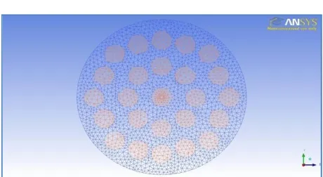
Figure 5: The model with air filter
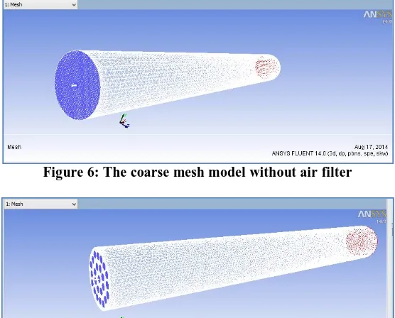
Next, the mesh of the two models was set. This was done by first finding the type of the mesh and then applying it to the model. In this study, two different types of meshes were observed. These are fine meshes and coarse meshes. Examples of a coarse mesh with and without the filter are shown in Fig. 6 andFig. 7while those of a fine mesh with and without filter are shown in Fig. 8 and Fig. 9 respectively.
Figure 6: The coarse mesh model without air filter
Figure 8: The fine mesh model without air filter
Figure 9: The fine mesh modelwith air filter
IV.EXPERIMENTAL RESULTS AND DISCUSSION
In this section, the experimental results are shown and are discussed in detail. The results for turbulence, velocity, temperature, and mole fraction are particularly discussed.
A. EXPERIMENTAL SETUP
In total, four simulations were carried out. These are: with perforation and with fine meshes, with perforation and with coarse meshes, without perforation and with fine meshes, and without perforation and with coarse meshes. These setups are also summarized in Table 2.
Table 2: Specifications of meshes used in simulations
Case Coarse mesh
(tetrahedral)
Fine mesh (tetrahedral) Without
perforation 300,000 235,0000
With perforation 232,000 1,100,000
ISSN(Online) : 2319-8753 ISSN (Print) : 2347-6710
I
nternational
J
ournal of
I
nnovative
R
esearch in
S
cience,
E
ngineering and
T
echnology
(An ISO 3297: 2007 Certified Organization) Website: www.ijirset.com
Vol. 6, Issue 1, January 2017
Figure 10: Convergence for the case of fine mesh with perforation.
B. DISCUSSIONOFRESULTS
The results obtained during the simulations are presented and discussed in detail below.
IV.B.1 TURBULENCE INTENSITY
Figure 11: Turbulent Intensity (in case of without perforation)
Figure 12: Turbulent Intensity (in case of with perforation)
IV.B. 2.FINE MESH VERSUS COARSE MESH
ISSN(Online) : 2319-8753 ISSN (Print) : 2347-6710
I
nternational
J
ournal of
I
nnovative
R
esearch in
S
cience,
E
ngineering and
T
echnology
(An ISO 3297: 2007 Certified Organization) Website: www.ijirset.com
Vol. 6, Issue 1, January 2017
Figure 13: Distribution of temperature for all the four cases.
The distributions of velocity for all the four cases are shown in Fig. 14. The results show that in the case of with perforation, velocity is higher and has narrower distribution for coarse mesh than for fine mesh.
Figure 14: The distribution of velocity for the four cases.
Fig. 15 shows the C3H8 mole fraction distributions for all the cases. The results show that in the case of fine mesh, the
Figure 15: Mole fraction distributions of C3H8 for the four cases.
The mole fraction distributions of CO2for the four cases are shown in Fig. 16. The results show that in the case of
with perforation, the distribution is narrower than in the case of without perforation.
ISSN(Online) : 2319-8753 ISSN (Print) : 2347-6710
I
nternational
J
ournal of
I
nnovative
R
esearch in
S
cience,
E
ngineering and
T
echnology
(An ISO 3297: 2007 Certified Organization) Website: www.ijirset.com
Vol. 6, Issue 1, January 2017
The mole fraction distributions of water vapour (H20) are shown in Fig. 17for all the cases. The results show that in
the case of with perforation, the distribution is wider. This is true for both the radial and longitudinal directions. Similarly, in the case of fine mesh, the distributions are smoother. Moreover, in the case of fine mesh, the distributions have smaller extent than in the case of coarse mesh.
Figure 17: Mole fraction distributions of H2O for the four cases.
The soot distributions for all the four cases are shown in Fig. 18. The results show that the soot does not begin to propagate and accumulate instantly rather it takes some time. Moreover, in the case of with perforation, the magnitude and distribution of the soot is larger. Similarly, in the case of fine mesh, the distributions are smoother and have lower values.
IV.B.3. QUANTITATIVE COMPARISONS
The temperature profiles for all the four cases are shown in Fig. 19.The results are shown for the case of vertical radial direction. Four different horizontal locations have been used. These include x = 0.1m, x = 0.2m, x = 0.3m, and x = 0.4m. The results show that the temperature values peak at positions near the fuel inlet. The results also show that the temperature of the flame is spread in the radial direction. Moreover, in case of perforation and coarse mesh, temperature is the highest while in case of perforation and fine mesh, the temperature is the lowest.
Figure 19: The temperature profiles for the four cases.
Next, the mole fractions of propane (C3H8) corresponding to all the four cases are shown in Fig. 20. The results are
ISSN(Online) : 2319-8753 ISSN (Print) : 2347-6710
I
nternational
J
ournal of
I
nnovative
R
esearch in
S
cience,
E
ngineering and
T
echnology
(An ISO 3297: 2007 Certified Organization) Website: www.ijirset.com
Vol. 6, Issue 1, January 2017
Figure 20: Mole fraction of propane (C3H8) for the four cases.
The mole fractions of CO2for the four cases are shown in Fig. 21.The results are shown for the case of vertical radial
Figure 21: Mole fractions of CO2for the four cases.
ISSN(Online) : 2319-8753 ISSN (Print) : 2347-6710
I
nternational
J
ournal of
I
nnovative
R
esearch in
S
cience,
E
ngineering and
T
echnology
(An ISO 3297: 2007 Certified Organization) Website: www.ijirset.com
Vol. 6, Issue 1, January 2017
Figure 22: Water vapour (H2O) profiles for the four cases.
V. CONCLUSIONS
REFERENCES
[1] Jagadeesha, T, “Internal Combustion Engine; Combustion Chambers,”in Department of Mechanical Engineering, Adichunchanagiri, 2010.
[2] Paul, S.C., Paul, M.C., Jones, W.P., "Large Eddy Simulation of a turbulent non-premixed propane-air reacting in a cylindrical combustor". Computers & Fluids, Vol. 39, pp. 1832-1847, 2010.
[3] Risi, A., Donateo, T., and Laforgia, D., “Optimization of the combustion Chamber of Direct Injection Diesel Engines,” in SAE Technical Paper, No. 2003-01-1064, 2003.
[4] Liu, F., Thomson, K.,Guo, H.,and Smallwood, G.,
“Numericalandexperimentalstudyofanaxisymmetriccoflowlaminarmethaneairdiffusionflameat pressures between5and40atmospheres,” in Combustionand Flame, Vol. 146, no. 3, pp. 456-471, 2006.
[5] Bufferand, H., Tosatto,L., LaMantia, B., Smooke,M., and Gomez, A., “Experimentalandcomputationalstudy
ofmethanecounterflowdiffusionflamesperturbedbytraceamountsofeitherjetfuelora6-componentsurrogateunder nonsootingconditions,” in
Combustion and Flame, Vol. 156, no. 8, pp. 1594-1603, 2009.
[6] Choi, G., Lee, J., Kwon, T., Ha, C., Lee, J., Chung, Y., Chang, Y., and Han, S., “Combustion characteristics of a swirl chamber type diesel
engine,” in Journal of Mechanical Science and Technology, Vol. 23, no. 12,pp. 3385-3392, 2009.
[7] Johansson, B., and Olsson, K.,“Combustion Chambers for Natural Gas SI Engines Part I: Fluid Flow and Combustion,” in International
Congress and Exposition Detroit, Michigan, 1995.
[8] Gouws, J.,“Combining a one-dimensional empirical and network solver with computational fluid dynamics to explore possible modifications
to a commercial gas turbine combustor,”.inFaculty of Mechanical/Aeronautical Engineering, University of Pretoria, Pretoria, 2007.
[9] Petrila, T., and Trif, D.,“Basics of Fluid Mechanics and Introduction to Computational Fluid Dynamics,”.in Springer Science & Business Media, Vol. 3, 2004.
[10] Fairweather, M., Jones, W. P., Ledin, H. S., and Lindstedt, R. P., "Predictions of soot formationin turbulent, non-premixed propane flames". In:
24th Symposium(international) on combustion,The Combustion Institute, Vol. 24, p. 1067–1074, 1992.
[11] Magnussen, B. F., and Hjertager, B. H., "On mathematical models of turbulentcombustion with special emphasis on soot formation and
combustion". In: 16th Symposium on Combustion, The Combustion Institute, 1976.
![Figure 2:The computational domain of the study [22].](https://thumb-us.123doks.com/thumbv2/123dok_us/1618853.1201082/3.595.102.529.182.377/figure-computational-domain-study.webp)