Dynamic Analysis and Comparison of
Multi-Storey L-Shaped and T-Shaped Building
Ayush Agrahari1, Prof. Sonal Pawar2, Prof Atul Pujari2
M.E 4th Semester (Structure), Department of Civil Engineering, K.J College of Engineering Research and
Management, Pune, Maharashtra, India1
Department of Civil Engineering, K.J College of Engineering Research and Management, Pune, Maharashtra, India2
ABSTRACT: The improper design and construction of the structures may cause great destruction to the structures. This has been proved by the earthquakes occurred in the recent past. So as it's essential to spot the seismal response of the structure even in high seismic zones to cut back the seismic damages in buildings. In the present work dynamic analysis and comparison of different shapes of building is carried out using ETABS 2013 software.
KEYWORDS: Different shapes, Dynamic analysis, Response Spectrum Method, Storey displacements, Storey drifts, ETABS.
I. INTRODUCTION
The effect of urbanization is exceptionally regular in the current past. The building and advancement of higher structures is genuinely necessary in today's era. Be that as it may, those structures can be harmed to a vast degree when the seismic tremors happen. In this way such structures should be dissected and outlined appropriately before building. Consistently about one lakh tremors of inexact extent more than three strike the earth and results in the loss of almost 15 million people. What's more, the strengthened solid structures additionally get harmed to a huge degree amid tremors in view of conflicting seismic reaction, abnormality in plan and mass of the building and so forth. Distinctive tremors have diverse extents and forces at various districts and the demolition brought on in these locales is additionally unique. Along these lines it is critical to concentrate the seismic conduct of RC structures for various quake works as far as reactions, for example, story removals, base shear and so on and it is additionally vital to make sense of the real seismic execution of the building that is perpetrated to tremor strengths.
II. RELATED WORK
1) Dr. S. K Dubey (2015) presented a paper on Dynamic Analysis Of Structures Subjected To Earthquake Load. He concerns with the study of seismic behavior of concrete reinforced building. The structure is analyzed by using time history method and response spectrum method. The pertaining structure of 20 stories residential building has been modeled.
2) Santosh kumar (2015) paper highlights on Comparative Static And Dynamic Study On Seismic Analysis Of Uniform And Non-Uniform Column Sections In A Building. The main aim of this paper is to analysis RCC frame by both static and dynamic method and to compare the difference between the two methods. By this paper we come to know about the comparative variation in storey displacements,,shearforces and strorey drifts in columns for both cases of the building where except column size, all loading condition are same.
obtained of two models are very much close. The pushover analysis and dynamic non linear analysis are performed to calculate the seismic performance of the hybrid structure.
OBJECTIVES
Main objectives of the project is to perform Dynamic analysis and to obtain Seismic performances of different shape of Structures located in moderate earthquake zone of India and to evaluate lateral forces, moment, deflections and storey drift & displacements, scaling factors & modal shapes. To contribute to the development of the design guidance for high rise buildings using Etabs software in relation to different shapes of building to control earthquake load as a reference for architects, engineers, developers, and students. To get familiar with the Etabs software.
III. METHODOLOGY
The methodology adopted for this study is, first modeling the considered structure in ETABS 2013 software and analyzing the same by Response Spectrum Method. The seismic analysis in India is done as according to the IS 1893 (Part 1).
Response spectrum method- In this concept the multiple modes of vibration of a structure can be used. This analysis can be used in many building codes for all except for simple or complex structures. The vibration of a building is defined as the combination of many special modes that are in a vibrating string corresponding to the “harmonics”. Computer aided structural analysis is used to determine these mode shapes for the structure. For every mode shape, from design spectrum responses are studied, with the help of parameters such as modal participation mass and modal frequency, and then they are combined to provide an evaluation of the total responses of the structure.
Problem Formulation
The structures are acted upon by different loads such as dead load (DL), Live load and Earthquake load (EL).
A.Self-weight of the structure comprises of the weight of the beams, columns and slab of the structure.
B.Dead load of the structure consist of Wall load, Parapet wall load and floor load, according to (IS 875(Part1)). 1) Wall load: weight unit of brick masonry X thickness of wall X height of the wall = 20 KN/m3 X 0.150m X 3m= 9 KN/m.
2) Wall load (of Parapet wall at top floor): weight unit of brick masonry X thickness of wall X height of the wall =20 KN/m3 X 0.15m X 1.2m= 3.6 KN/m.
C.Live load: It consist of Floor load which is taken as 4KN/m2 and Roof load as 2 KN/m2, according to (IS 875(Part 2).
D.Seismic Load: The different seismic parameters are taken as follows, IS 1893(Part-1):2002.
Seismic zone: IV (Z=0.24).
Soil type: II.
Importance factor: 1.
Response reduction factor: 5.
Plan Details
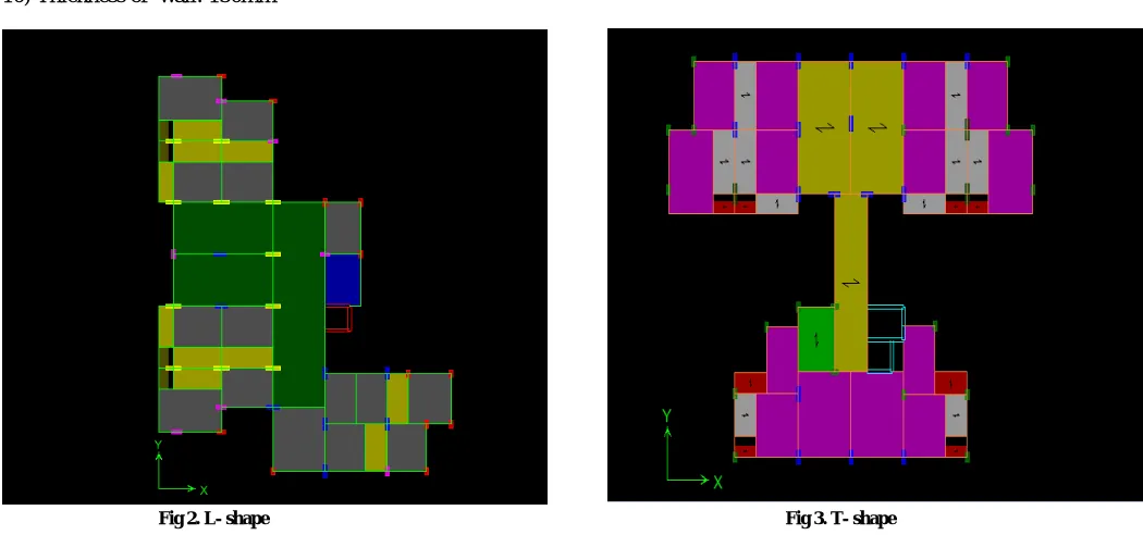
Basically model consists of multiple bay fifteen storey building, each bay having width of 4m. The storey height between two floors is 3.0m with beam and column sizes of 0.45x0.45m respectively and also the slab thickness is taken as 0.125m.Shape of the building for all the cases is shown in figure.
The material properties and geometry of the model are described below
2) Support conditions: Fixed 3) Storey height: 3 m
4) Grade of concrete: 30 Mpa 5) Grade of steel: Fe500
6) Size of columns from 1-5 storey: 650mm x 650mm 7) Size of columns from 6-15 storey: 500mm x 500mm 8) Size of beams: 450mm x 450mm
9) Height of parapet wall: 1.2m 10) Thickness of wall: 150mm
Fig 2. L- shape Fig 3. T- shape
IV. RESULTS AND DISCUSSION
For determining the most stable structure among all models that we have studied, graphs, calculations and tables have drawn for different shapes.
3.1 Storey Maximum and Average Lateral Displacement
a) For L-shaped Building Permissible Value = H/500 H = Total ht of building
Permissible Value = 43.5 x1000/500 = 87 mm Calculated Value
At roof lateral displacement is maximum so we consider the value of roof from software. Roof
b) For T-shaped Building Permissible Value = H/500 H = Total ht of building
Permissible Value = 43.5 x1000/500 = 87 mm Calculated Value
At roof lateral displacement is maximum so we consider the value of roof from software. Roof
EQx = 0.0661 x 1000 = 66.1 mm< 87 mm Hence safe.
From above results it is seen that the value of storey maximum and average lateral displacement is least in L- shaped building so it is efficient in lateral displacement.
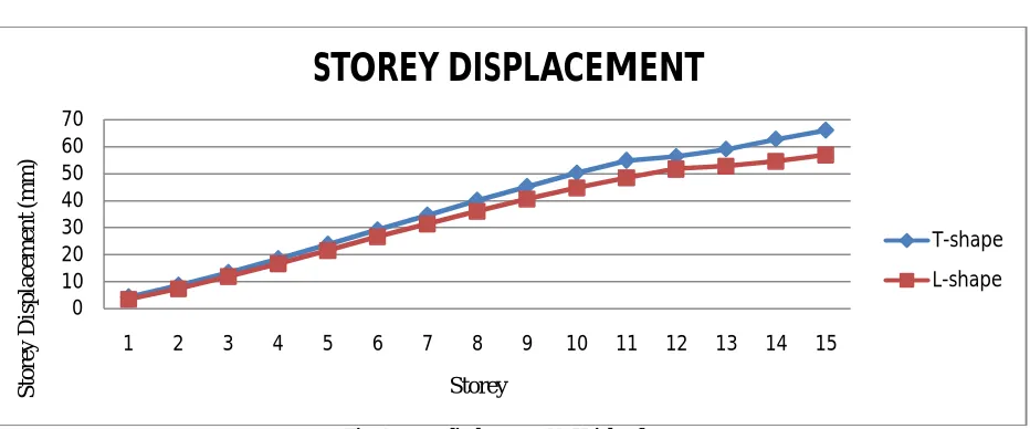
Fig. 4 Storey displacement Vs Height of storey
Above Fig.4 shows that the maximum storey displacement increases with the increase in height of the storey. Displacement for L-shape of the building is less compare to T- shape building.
3.2 Story Drifts
a) For L-shaped Building Permissible value = h/250 h= storey to storeyht = 3m
Permissible value = 3000/250 = 12mm Calculated Value
Storey 5
EQx = 1/2819 = 3000/470 = 6.28mm<12mm Hence safe.
b) For T-shaped Building Permissible value = h/250 h= storey to storeyht = 3m
Permissible value = 3000/250 = 12mm Calculated Value
Storey 5
EQx = 1/459 = 3000/459 = 6.53mm<12mm Hence safe. 0 10 20 30 40 50 60 70
1 2 3 4 5 6 7 8 9 10 11 12 13 14 15
0 2 4 6 8 10 12 14
1 2 3 4 5 6 7 8 9 10 11 12 13 14 15
S
to
re
y
D
ri
ft
(m
m
)
Storey
STOREY DRIFT
L-shape T-shape
From above results it is seen that the value of storey drift is least in L- shaped building so it is most efficient.
Fig. 5 Shows variation of Storey Drift with Height of storey
Storey drift increases with increase in height of the storey up to 5th storey reaching to maximum value and then it again started decreasing.
3.3 Modal Information
TABLE 1
DATA FROM DYNAMIC ANALYSIS (L-SHAPE MODEL)
TABLE 2
DATA FROM DYNAMIC ANALYSIS (T-SHAPE MODEL)
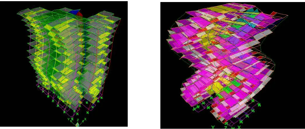
From the dynamic analysis, mode shapes are generated and it is concluded that T-shape building undergoes more deformation than L-shape building.
3.4 Maximum Bending Moment And Maximum Shear Force
TABLE 4
MAX B.M. AND SHEAR FORCE OF BEAM & COLUMN
Max B.M. and Shear Force of Beam
Forces L-shaped T-shaped
B.M. My 391.59 263.309
B.M. Mz 0 0
S.F. Fy 240.52 340.7
Max B.M. and Shear Force of Column
Forces L-shaped T-shaped
Axial Force Fx 1820.69 2013.65
S.F. Fy 295.19 243.03
S.F. Fz 81.94 14.29
B.M. My 897.085 922.572
B.M. Mz 111.831 25.645
V. CONCLUSIONS
Irregular shapes are severely affected during earthquakes especially in high seismic zones.
The Fig.6 shows that irregular shape building undergo more deformation and hence regular shape building must be preferred.
Mode Period Frequency Modal Mass Partcipating Ratio
X-Trans Y-Trans Rz-Rot 1 1.73294
1.54477
0.57705 51.52 3.32 41.72
2 0.64734 6.46 71.71 5.05
3 1.35327 0.73895 41.87 1.78 32.79
Mode Period Frequency
Modal Mass Partcipating Ratio
X-Trans Y-Trans Rz-Rot
1 1.79860 0.55599 9.90 29.16 42.31
2 1.54078 0.64902 29.44 41.18 11.19
The design and analysis of G+15 buildings are safe in Maximum Displacement , Storey Drift .As thecalculated values are less than permissible values so the building is safe in every respect.
REFERENCES
1) Naoki NIWA1, ET.AL, "Exploration On Advanced Structural Framing System For High-ascent Office Buildings",13th World Conference on Earthquake Engineering Vancouver, B.C., Canada August 1-6, 2004, Paper No. 53.
2) JIANGJun1, ET.AL, "Seismic Design of A Super High-ascent Hybrid Structure", The fourteenth World Conference on Earthquake Engineering October 12-17, 2008, Beijing, China.
3) Prof.K.K.Sangle, Structural Engineering Department, VJTI, Matunga, Mumbai, "Seismic Analysis Of High-ascent Steel Frame With Or Without Bracin", 15 WCEE, ASCE (2012)
4) Santosh Kumar,ET.AL, "Relative Static and Dynamic Study on Seismic Analysis of Uniform and Non-Uniform Column Sections in a Building", International Journal of Innovative Research in Science, Engineering and Technology (An ISO 3297: 2007 Certified Organization),Vol. 4, Issue 8, August 2015.
5) Jyothi. C. Hawaldar, ET.AL, "Tremor Analysis Of A G+12 Story Building With And Without Infill For Bhuj And Koyna Earthquake Function", International Research Journal Engineering and Technology (IRJET), Volume: 02 Issue: 05 | Aug-2015 .