Division VII
STRUCTURAL INTEGRITY ASSESSMENT OF SPENT NUCLEAR FUEL
ROD UNDER DROP ACCIDENT CONDITION
Belal Almomani1, Dongchan Jang2, and Sanghoon Lee3
1 Graduate Student, Nuclear and Quantum Engineering, KAIST, Korea 2 Assistant Professor, Nuclear and Quantum Engineering, KAIST, Korea
3 Assistant Professor, Mechanical and Automotive Engineering, Keimyung University, Korea
ABSTRACT
The structural integrity of spent fuel assembly is a key element for flexible and economic management of spent nuclear fuel (SNF) considering handling and transportation operations in most of the management scenarios. In order to better understand the SNF rod behavior under drop accident condition and to study the effects of various uncertain parameters on the fuel rod structural integrity, a detailed finite element (FE) model for pressurized water reactor (PWR) fuel rod is being developed using ABAQUS. This paper describes the FE model and discusses the influence of the parameters relevant to design safety with concern of post-irradiated fuel conditions such as degradation of cladding mechanical properties, pellet-to-cladding mechanical interaction (PCMI), spacer grids (SGs) spring stiffness degradation, rod internal pressure (RIP). Based on the proposed model and preliminary simulation results of sensitivity analysis, we can initially prioritize the importance of data in managing and studying the structural integrity of the SNF for the next assessment stage. This work is part of a bigger research on the structural integrity of SNF in cask-loaded condition, whereby it might help in proposing guidelines for safe handling of SNF.
INTRODUCTION
Wet and dry storages are widely used technologies to safely store the spent nuclear fuel (SNF) for several decades. Nonetheless, transfer SNF from wet to other types of longer term storage may occur multiple times before reprocessing or final disposal, due to accumulation problem or to enhance the safety and security level. This activity would probably make abrupt changes to the environment around the SNF assemblies and may lead to undesirable consequences on the fuel integrity. Moreover, the major requirements of SNF for long-term storage under normal storage conditions are to maintain fuel cladding integrity by complying the regulatory requirements of transportability and retrievability, and to provide adequate cooling and environmental control to prevent fuel degradation as stated by Liu (2015). Thus, technical issues on retrievability and cladding integrity with the concern of storage conditions and the aging effects should be investigated as major obstacles for safe handling, safe transportation operations, and economic management of SNF.
important input parameters, and applicable methodology. In the next assessment stage, the combination effect of the four parameters on fuel rod response, failure criteria of fuel cladding, and critical drop heights will be considered in an integrated analysis to provide results and insights for use in developing a guideline for safe handling of SNF.
FE MODEL DEVELOPMENT & STORAGE CONDITION
FE model development
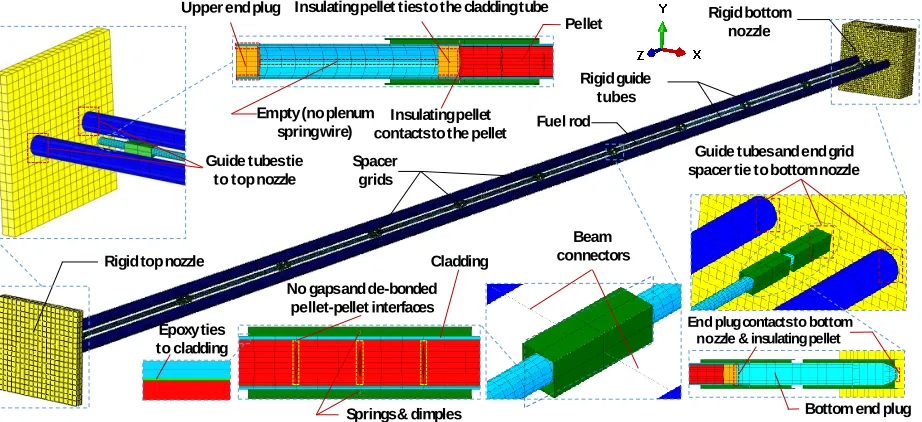
The FE model of a single fuel rod has been developed, including all the structural features, to study the individual behavior of fuel rod under drop condition. The fuel rod was modelled with the actual dimensions of 350 fuel pellets in a 4.094-m-long fuel cladding referred to CE16x16 Plus 7 fuel type, as well as 2 end plugs, 2 insulating pellets, 2 guide tubes, top/bottom nozzles, and 12 SGs (see Figure 1) were all modelled to investigate the interaction of fuel rod against the supporting components. This model is designed in a way to provide useful results that can be transferred to fuel assembly level model in a cask-loaded condition.
Figure 1. Fuel rod model-finite element details.
Regarding the boundary conditions, the guide tubes are rigidly attached to the nozzles via the tie constraints. These parts are restrained in translational directions (X, Y) for vertical drop and in (X, Z) directions for horizontal drop, and in all rotational directions (RX, RY, RZ) for both cases to make ideal drop orientations. The SGs are also restrained in (X, Y) in the vertical drop, and (X, Z) in the horizontal drop, and (RX, RY, RZ) directions for both cases, as well as connected to the guide tubes by rigid beam connectors (BEAM) that imposes kinematic constraints to apply a fixed distance between two adjacent SGs during the drop response. The fuel rod has free motions in all the directions; however, it is connected by SGs springs and dimples using spring element (SPRINGA). The friction effect between the fuel rod and SGs is ignored. The pellet-clad gap is filled with an epoxy layer supplying cohesion bonding, and the pellet-pellet interfacial is de-bonded without a gap.
The explicit linear hexahedral solid elements type (C3D8) is used for SGs and insulating pellets, while (C3D8R) is utilized for pellets. (C3D8I) element type is selected for cladding and epoxy tubes, since the incompatible model elements can capture bending more accurately. The nozzles, guide tubes, and the pad are all defined as rigid bodies that do not deform but can undergo large rigid body motions to evaluate the
Rigid guide tubes
Rigid bottom nozzle
Fuel rod
Spacer grids
Rigid top nozzle
Guide tubes tie to top nozzle
Guide tubes and end grid spacer tie to bottom nozzle Insulating pellet ties to the cladding tube
Empty (no plenum spring wire)
Bottom end plug End plug contacts to bottom
nozzle & insulating pellet Insulating pellet
contacts to the pellet
Beam connectors
Pellet
Epoxy ties to cladding
No gaps and de-bonded pellet-pellet interfaces
Cladding
individual behavior of the fuel rod. The mesh length of cladding, epoxy, and pellets is 3.79 mm, and the total number of elements for the fuel rod is roughly 130,000 elements.
All the materials are modelled as isotropic elastic-plastic with hardening. The material properties of SGs and epoxy are listed in Table 1, while material properties of cladding and pellets are obtained from complex mechanical material models that proposed by Geelhood et al. (2008) and Adkins et al. (2013), which will be addressed in Material Properties Section. The contact property is tangential behavior with frictionless, and normal behavior with a hard contact that applied in the general contact algorithm (coulomb friction model) to all the contact pairs. The FE analysis studies a free response of a single fuel rod subjected to kinematic excitation, and evaluates the strain results of the first peak values of deflection.
Table 1: Mechanical properties of Zr-4 strap and epoxy layer Part Material type Properties
Spacer grids Zry-4 strap* Density (kg/m3): 6550 Elastic modulus (GPa): 114 Yield strength (MPa): 379 Poisson’s ratio: 0.296 Epoxy Epoxy adhesive** Density (kg/m3): 1251
Elastic modulus (GPa): 3.5 Yield strength (MPa): 69 Poisson’s ratio: 0.37
* Song et al. (2010), ** Jiang et al. (2016)
Storage and impact conditions
The temperature history is an important variable for evaluating SNF behavior during storage and post-storage transportation accidents. The initial temperature, at vacuum drying stage, is somewhat around 400°C but decreases gradually influenced by the radioactive/heat decay. The temperature drops typically from 400°C to 250°C in the first ten years (Martin et al., 2009). The neutron fluence (or burnup) is also considered as a significant variable that affects the mechanical properties and failure criteria; particularly fracture toughness of irradiated Zircaloy. The cladding fluence associated with high burnup fuel (HBF) of 45~60 GWd/MTU in a pressurized water reactor (PWR) is roughly ranged from 7 to 12 ×1025 n/m2 (EPRI, 1991). In regards to hydride formation, the primary hydrating results from residual moisture in the fuel pellet and corrosion. Increasing levels of hydrogen concentration reduce the ductility of irradiated Zircaloy and the degree of plastic deformation that has been sustained at fracture and behave like a brittle. For discharge burnup in the range of 45-60 GWd/MTU, the average hydrogen concentration is ranged between 200-600 ppm (EPRI, 1991), (SNL, 1992). These variables make a momentous influence on the structural integrity of spent nuclear fuel associated with the material degradation and failure criteria. Therefore, the effect of lower and upper bounds storage conditions within the first ten years has been studied in the sensitivity analysis.
be utilized in future fuel assembly cladding failure analysis. It should be noted that the pinch strain results caused by rod to SG interactions are eliminated from the results; as detailed model of SG is still under development.
SENSITIVITY ANALYSIS
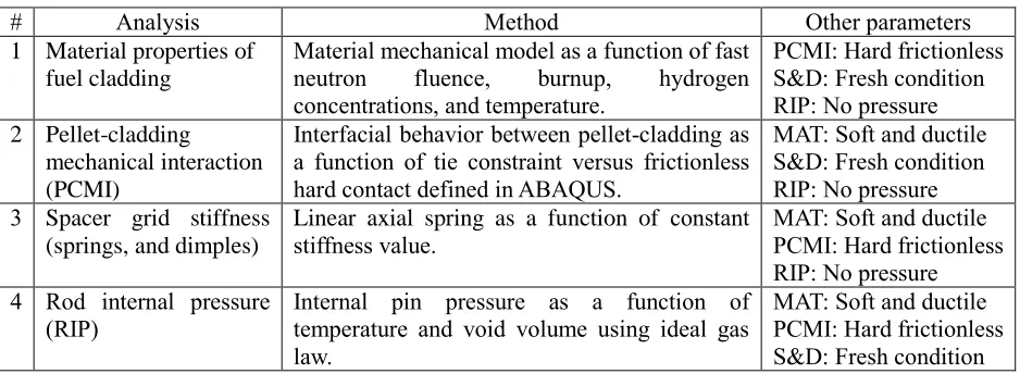
The sensitivity analyses are performed for high degree uncertain parameters that listed in Table 2 to demonstrate the impact of each parameter on the resulting stress and strain predictions. Detailed explanation and full results of these analyses are shown in the following sections.
Table 2: Sensitivity analyses to be performed for this initiative
# Analysis Method Other parameters
1 Material properties of fuel cladding
Material mechanical model as a function of fast neutron fluence, burnup, hydrogen concentrations, and temperature.
PCMI: Hard frictionless S&D: Fresh condition RIP: No pressure 2 Pellet-cladding
mechanical interaction (PCMI)
Interfacial behavior between pellet-cladding as a function of tie constraint versus frictionless hard contact defined in ABAQUS.
MAT: Soft and ductile S&D: Fresh condition RIP: No pressure 3 Spacer grid stiffness
(springs, and dimples)
Linear axial spring as a function of constant stiffness value.
MAT: Soft and ductile PCMI: Hard frictionless RIP: No pressure
4 Rod internal pressure
(RIP) Internal pin pressure as a function of temperature and void volume using ideal gas law.
MAT: Soft and ductile PCMI: Hard frictionless S&D: Fresh condition
Material properties
The recent studies indicate that the fuel cladding integrity is susceptible toirradiation effects, temperature, and hydrogen concentration that may lead to transforming it from being a ductile material to a brittle material as so-called cladding embrittlement phenomenon. Consequently, the probability for damage of fuel cladding under normal or accident shipping conditions will increase. Therefore, the material property of fuel cladding is seen as an important parameter to evaluate the fuel rod response during accident shipping conditions.
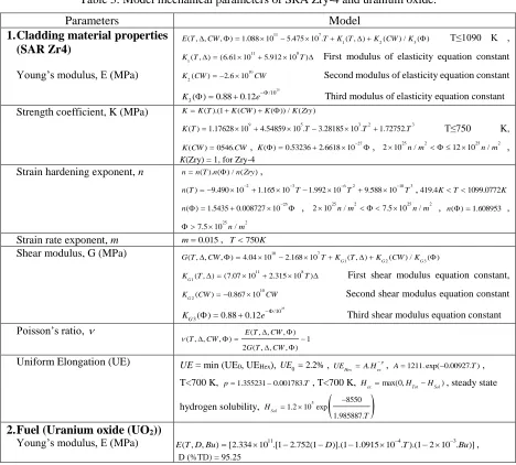
In this study, elastic and plastic properties of cladding materials are entry data of mechanical behavior of the fuel rod. Mechanical material models to predict elastic-plastic properties and true stress-strain curve are adopted from Geelhood et al. (2008) and Adkins et al. (2013), as given in Table 3. These models are developed as a function of neutron fluence, burnup rate, hydrogen concentrations, oxide thickness, temperature, cold work ratio, and strain rate. The temperature, neutron fluence, hydrogen concentration, and burnup variables have a high degree of correlation, but it may be difficult to interpret because of large uncertainty. Therefore, eight combinations of lower and upper bounds storage conditions have been applied to get several mechanical material properties of cladding and pellet as listed in Table 4. Complex constitutive material laws (correlations of Hooke’s law and power law) were used for the irradiated Zircaloy cladding in this study, as given in Eqs. (1- 3).
. e pn 1000 m
K
(1)
1 1
1000 m n
y n
K E
(2)
y p e UE
E
(3)
Table 3: Model mechanical parameters of SRA Zry-4 and uranium oxide.
Parameters Model
1.Cladding material properties (SAR Zr4)
Young’s modulus, E (MPa)
11 7
1 2 3
( , , , ) 1.088 10 5.475 10 . ( , ) ( ) / ( )
E T CW TK T K CW K T≤1090 K ,
11 8
1( , ) (6.61 10 5.912 10 )
K T T First modulus of elasticity equation constant 10
2( ) 2.6 10
K CW CW Second modulus of elasticity equation constant
25 /10 3( ) 0.88 0.12
K e Third modulus of elasticity equation constant
Strength coefficient, K (MPa) KK T( ).(1K CW( )K( )) / K Zry( )
9 5 3 2 3
( ) 1.17628 10 4.54859 10 . 3.28185 10 . 1.72752.
K T T T T T≤750 K,
( ) 0546.
K CW CW, K( ) 0.532362.6618 10 27, 2 10 25n m/ 2 12 10 25n m/ 2 ,
K(Zry) = 1, for Zry-4 Strain hardening exponent, n nn T n( ). ( ) / ( n Zry),
2 3 6 2 10 3
( ) 9.490 10 1.165 10 1.992 10 9.588 10
n T T T T ,419.4KT1099.0772K 25
( ) 1.5435 0.008727 10
n , 25 2 25 2
2 10 n m/ 7.5 10 n m/ , n( ) 1.608953 ,
25 2
7.5 10 n m/
Strain rate exponent, m m0.015, T750K
Shear modulus, G (MPa) 10 7
1 2 3
( , , , ) 4.04 10 2.168 10 G( , ) G( ) / G( )
G T CW TK T K CW K
11 8
1( , ) (7.07 10 2.315 10 )
G
K T T First shear modulus equation constant,
10 2( ) 0.867 10
G
K CW CW Second shear modulus equation constant
25 /10 3( ) 0.88 0.12
G
K e Third shear modulus equation constant
Poisson’s ratio, ( , , , )
( , , , ) 1
2 ( , , , )
E T CW T CW
G T CW
Uniform Elongation (UE) UE = min (UE0, UEHex),
0 2.2%
UE , UEHex A H. exp, A1211. exp( 0.00927. ) T ,
T<700 K, p1.3552310.001783.T, T<700 K, max(0, )
ex Tot Sol
H H H , steady state
hydrogen solubility, 5
8550
1.2 10 exp 1.985887.
Sol
H
T
2.Fuel (Uranium oxide (UO2))
Young’s modulus, E (MPa) 11 4 3
( , , ) [2.334 10 .[1 2.752(1 )].(1 1.0915 10 . ).(1 2 10 . )]
E T D Bu D T Bu ,
D (%TD) = 95.25
SRA: stress relieved annealed
Table 4: Model mechanical parameters of SRA Zry-4 and uranium oxide.
Parameters Mechanical properties of fuel rod as a function of storage condition
MAT-1 MAT-2 MAT-3 MAT-4 MAT-5 MAT-6 MAT-7 MAT-8 1.Zircaloy cladding (SRA Zry-4)
a. Mass density, 𝜌 (kg/m3)
b.Modulus of elasticity, E (GPa) c. Strength coefficient, K (GPa) d.Strain Hardening Exponent, n e. Strain Rate Exponent, m f. Shear modulus, G (GPa) g.Poisson’s ratio, v
h.Uniform plastic elongation, UE i. Yield stress, 𝜎𝑦 (MPa)
j. Ultimate tensile strength, 𝜎𝑒+𝑝 (MPa)
6590 77.64 15.21 0.171 0.015 29.22 0.328 0.011 764.92 868.85 6590 77.64 15.21 0.171 0.015 29.22 0.328 0.006 764.92 834.27 6590 77.64 16.22 0.172 0.015 29.22 0.328 0.011 824.88 931.05 6590 77.64 16.22 0.172 0.015 29.22 0.328 0.006 824.88 895.36 6590 68.43 11.1 0.127 0.015 25.58 0.337 0.009 685.04 744.97 6590 68.43 11.1 0.127 0.015 25.58 0.337 0.022 685.04 794.378 6590 68.43 10.41 0.127 0.015 25.58 0.337 0.009 637.28 696 6590 68.43 10.41 0.127 0.015 25.58 0.337 0.022 637.28 743.42 2.Fuel (Uranium oxide (UO2))
a. Mass density, 𝜌 (kg/m3)
b.Modulus of elasticity, E (GPa) c. Poisson’s ratio, v * d.Yield stress, 𝜎𝑦 (MPa) *
10440 174.1 0.32 2146 10440 174.1 0.32 2146 10440 168.3 0.32 2146 10440 168.3 0.32 2146 10440 165.4 0.32 2146 10440 165.4 0.32 2146 10440 171.1 0.32 2146 10440 171.1 0.32 2146 Strain rate = 1/s, cold work = 50%, and O2 concentration = 0.0012 kg O2 / kg Zr4.
* Jiang et al. (2016)
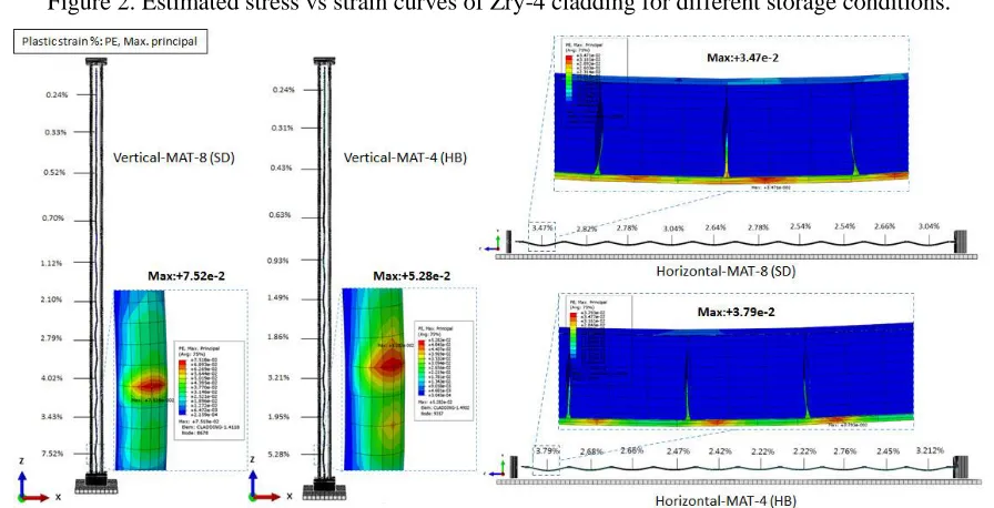
Figure 2. Estimated stress vs strain curves of Zry-4 cladding for different storage conditions.
Figure 3. PE, max. principal of cladding at interspaces grid locations for hard and soft rod materials under vertical and horizontal drops.
Soft and ductile
Hard and brittle YS,YS YS,YS
YS,YS
YS,YS
Pellet-cladding mechanical interaction (PCMI)
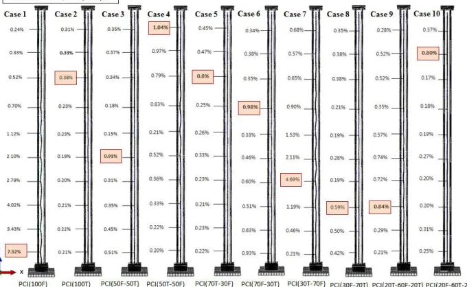
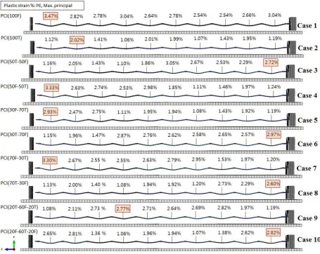
The fuel pellets and cladding are normally fused together by chemical and mechanical interactions during the reactor operation condition. PCMI behavior has a high influence on flexural rigidity and stiffness of fuel rod; as a result of increasing or decreasing the nominal bending stress under an energetic loading (Wang et al., 2013). Therefore, the interaction between the fuel and the cladding is a major consideration that should be treated in detail to ensure accurate representation of the effect of PCMI on cladding failure. However, this study does not contain the detailed analysis of chemical-physics and thermos-mechanical aspects. Furthermore, expansion, swelling, and creep relaxation of pellets and the associated deformations on cladding are not considered in the fuel rod model. Instead, an adhesive epoxy layer is added to fill the gap between the fresh fuel rod cladding and pellets to simulate cohesion bonding. In addition, the fuel rod is deemed to be not bowed which typically caused for SNF when exhibiting deviation from strengthens after exposure to a neutron fluence (SNL, 1992). Ten generalized interface bonding and de-bonding conditions have been implemented using frictionless hard contact property and surface-based tie constraint (permanently glued surfaces) to provide a fundamental understanding of the interface bonding efficiency for the fuel rod composite system as shown in Figure 4. Figure 5 & 6 depict the plastic strain distribution results over the entire rod for the ten interfacialbonding cases in vertical and horizontal drop conditions.
Figure 4. Pellet-clad bonding and de-bonding interfacial conditions for vertical and horizontal drops.
Figure 5. PE, max. principal of cladding at interspaces grid locations for several pellet-clad interfacial bonding conditions for vertical drop condition.
Case 1 Case 2 Case 3 Case 4 Case 5 Case 6 Case 7 Case 8 Case 9 Case 10
1 0 0 % F ri cs -H ard 1 0 0 % T ie 5 0 % F ri cs -H ar d 5 0 % T ie 5 0 % F ri cs -H ard 5 0 % T ie 7 0 % T ie 3 0 % T ie 3 0 % T ie 7 0 % T ie 2 0 % T ie 2 0 % T ie 3 0 % F ri cs -H ar d 7 0 % F ri cs -H ard 7 0 % F ri cs -H ard 3 0 % F ri cs -H ard 6 0 % F ri cs -H ard 2 0 % F ri cs -H ard 2 0 % F ri cs -H ar d 6 0 % T ie Case 1 Case 2 Case 3 Case 4 Case 5 Case 6 Case 7 Case 5 Case 9 Case 10 100% Frics-Hard 100% Tie 50% Frics-Hard 50% Tie
50% Frics-Hard 50% Tie
70% Tie
30% Tie 30% Tie
70% Tie
20% Tie 20% Tie
30% Frics-Hard 70% Frics-Hard 70% Frics-Hard 30% Frics-Hard 60% Frics-Hard 20% Frics-Hard 20%
Figure 6. PE, max. principalof cladding at interspaces grid locations for several pellet-clad interfacial bonding conditions for horizontal drop condition.
Case 1 (100% de-bonding condition) shows an extensive plastic deformation on the cladding comparing to case 2 (100% bonding condition) that shows the lowest plastic strain values in both drop condition. This happened due to the fact that the permanently tied bonding increases the flexural rigidity and the resistance of undergoing bending of the fuel rod. In the case of realistic PWR fuel, the fuel-clad adhesion as determined by active mass portion is ranged from 75 to 100% in the fuel response model (SNL, 1992). Therefore, the configurations of case 5, 8, and 10 are considered as more realistic than the other cases. Overall, it is concluded that the PCMI can highly alter the location and magnitude of maximum plastic strain with a significant effect on fuel rod response under drop condition and thus affects the probability of fuel rod failure.
Spacer grid stiffness & rod internal pressure (RIP)
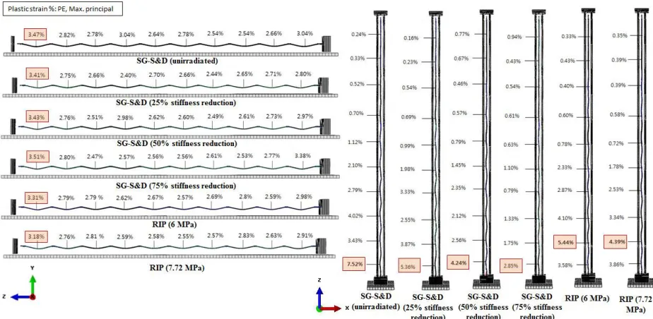
the literature. Preliminary, three stiffness reduction percentages (25%, 50%, 75%) of fresh springs and dimples have been examined representing the radiation-induced changes.
The RIP is also an important parameter to be considered regarding cladding mechanical performance for storage and subsequent transportation (Bratton, 2017). The internal pressure from fission gases drops proportionally to the temperature drops during the storage period. The RIP has been estimated using the ideal gas law, where the most common void volume for the standard PWR fuel is 14.5 cm3 (Bratton, 2017). Therefore, RIP of the lower limit is 6 MPa at temperature 250 °C and the upper limit is 7.72 MPa at temperature 400 °C. Figure 7 shows the distribution of plastic strains results for the RIP and SG stiffness analyses. The PE max. principal difference decreased 14.4%, 35%, and 70% in vertical drop, and decreased 4%, 2.2%, 1.9% in the horizontal drop when the springs and dimples stiffness decreased 25%, 50%, and 75%, respectively. PE max. principal difference decreased 13% in vertical drop, and 1.4% in the horizontal drop when the RIP increased from 6 MPa to 7.72 MPa. The effect of RIP looks reduces the stress concentration caused by the pellet-to-clad bonding. Yet, the effect of springs and dimples stiffness with regards of energy absorption during the impact will be investigated in the future studies to justify a reasonable fuel rod response.
Figure 7. PE, max. principalof cladding at interspaces grid locations for spacer grid stiffness & rod internal pressure analyses under vertical and horizontal drop conditions.
CONCLUDING REMARKS
sensitivity on the strain deformation results; however, developing a detailed model of SGs is recommended. The combination effects of the parameters on the fuel rod response and the interaction on each other in the modeling and analysis will be heavily investigated under different hypothetical initial drop conditions in the future work to provide guidelines for maintaining the structural integrity for long-term storage of SNF.
ACKNOWLEDGMENTS
This work was supported by the Nuclear Safety Research Program through the Korea Foundation of Nuclear Safety (KOFONS), granted financial resources by the Nuclear Safety and Security Commission (NSSC), Republic of Korea (No. 1305032).
REFERENCES
Liu, Y.Y. (2015) “18 - Wet storage of spent nuclear fuel, in Safe and Secure Transport and Storage of Radioactive Materials,” 299-310, Elsevier, Oxford, UK.
Rashid, J. Y. R., & Machiels, A. J. (2005). “A methodology for the evaluation of fuel rod failures under accident conditions. Packaging, Transport, Storage & Security of Radioactive Material,” 16(3),
211-218.
Adkins, H., Geelhood, K., Koeppel, B., Coleman, J., Bignell, J., Flores, G., ... & Klymyshyn, N. (2013) “US Department of Energy, Used Fuel Disposition Campaign, Used Nuclear Fuel Loading and Structural Performance under Normal Conditions of Transport— Demonstration of Approach and Results on Used Fuel Performance Characterization,” (No. DOE/NE--20130930HA; FCRD-UFD--2013-000325).
Geelhood, KJ., Beyer, CE., and Luscher, WG. (2008) “PNNL stress/strain correlation for Zircaloy”, (No. PNNL-17700).
Song, K. N., Lee, S. H., Lee, S. B., Lee, J. J., & Park, G. J. (2010) “Study on the lateral dynamic crush strength of a spacer grid assembly for a LWR nuclear fuel assembly,” Transactions of the Korean
Society of Mechanical Engineers A, 34(9), 1175-1183, Korean.
Jiang, H., Wang, J. A. J., & Wang, H. (2016). “The impact of interface bonding efficiency on high-burnup spent nuclear fuel dynamic performance,” Nuclear Engineering and Design, 309, 40-52.
Martin, O., Nilsson, K. F., Györi, C., van Uffelen, P., & Schubert, A. (2009). “Creep Simulation of Nuclear Fuel Cladding under long-term storage conditions with TRANSURANUS,” EUR 23926 EN – Joint Research Centre–Institute for Energy.
Electric Power Research Institute (EPRI) (1991), “Fuel-Assembly Behavior Under Dynamic Impact Loads Due to Dry-Storage Cask Mishandling”, (No. NP-7419).
Wang, J. A. J., Jiang, H., Wang, H., Bevard, B., & Howard, R. (2013). “The Impact of Interface Bonding Efficiency on High-Burnup Spent Nuclear Fuel Vibration Integrity during Normal Transportation”, (No. ORNL/TM-2013/296).
Sandia National Laboratory (SNL) (1992). “A Method for Determining the Spent-Fuel Contribution to Transport Cask Containment Requirements”, (No. SAND90-2406).
Ballheimer, V., Wille, F., & Droste, B. (2010). Mechanical safety analysis for high burn-up spent fuel assemblies under accident transport conditions. Packaging, Transport, Storage & Security of
Radioactive Material, 21(4), 212-217.
ABAQUS Unified FEA, Ver. (2014). " 6.14-4, Abaqus/CAE User’s manual."
Jiang, H., & Wang, J. A. J. (2016). “Spent nuclear fuel system dynamic stability under normal conditions of transportation,” Nuclear Engineering and Design, 310, 1-14.