Structural Analysis of Steam Generator Primary Divider Plate under LOCA
Conditions
Nick Idvorian1), Junjie Cao2), and Ernest Mileta3)
1) Manager, Design Engineering, Babcock & Wilcox Canada, Cambridge, ON ([email protected]) 2) Principal Engineer, Nuclear Engineering, Babcock & Wilcox Canada, Cambridge, ON ([email protected]) 3) Senior Design Engineer, Ontario Power Generation, Pickering, ON ([email protected])
ABSTRACT
Elastic/plastic dynamic analyses were performed to justify a design modification to a steam generator divider plate assembly by using General Purpose Finite Element (FE) code ABAQUS/Explicit. Interactive ABAQUS/Thermal Hydraulic analyses were used to determine the responses of the assembly to LOCA conditions. In addition, pressure was applied to the model in both forward and backward directions and increased continuously until disengagement of the divider plate. Pressure corresponding to first component failure, pressure vs. deformation volumes and final disengagement were obtained from the analyses and used for safety assessment of the assembly. It has been proved that the modified divider plate assembly can withstand higher pressure loads in both forward and backward directions and no new loose parts are generated due to the modification.
INTRODUCTION
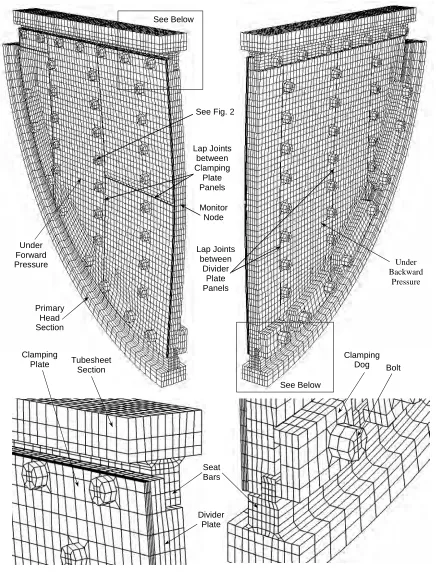
The design of the steam generator divider plate consists of a number of vertical flat plate segments or panels bolted together that divides the steam generator primary head into two compartments: the inlet side and the outlet side, as shown in Figure 1. This type of divider plate design was used in the early Re-circulating Steam Generators units. Under normal operating condition, the pressure drop from the inlet side to the outlet side is in the order of 193 kPa (28.0 psi). Under a postulated loss of coolant accident (LOCA) condition, e.g. a pipe rupture near or further down stream from the steam generator inlet or outlet nozzle, the pressure differential is substantially higher.
Due to leakage of D2O through the panel joints and its negative effect on header temperature, the divider plates of steam generators were modified by installation of a “skin fix’. This new modified design of the divider plate consists of three layers: the old divider plate panels on the cold leg side with the sealing skin and the clamping plate on the hot leg side. In this design, a 0.762 mm (0.030″) thick Inconel Alloy 625 skin with crimped peripheral edges is added to the hot leg side of the divider plate. The crimped edges are pressed against the seating bars welded to the tubesheet and primary head and thus provide a sealing function against the inlet to outlet head pressure. The vertical seams of the skin panels are arranged between the divider plate panel seams. Clamping plate panels (carbon steel SA-516 GR 70, 6.35 mm (0.25″) thick) are used to clamp the skins over the divider plate panels. The bolts used for the divider plate panels, as shown in Figure 2, are extended through the clamping plate panels and connected with nuts. The bolts are tightened from head side to connect the divider plate panels, which are threaded, and tightened from nut side to connect the skin and clamping plate panels.
The design modification was justified by Finite Element (FE) analysis using ABAQUS/Explicit [3]. Impact of the modification on structural behaviour of the divider plate assembly under accident (LOCA) conditions was investigated and the flexibility of the divider plate assembly was integral to the supporting Thermal-Hydraulic analysis. In general terms, the new design should be capable of withstanding higher pressure loading and no new loose parts should be generated. To support the safety analysis specific results were required: (a) a load vs. displaced volume curve; (b) an updated coupled Thermal-Hydraulic/Structural analysis; (c) an approximate failure limit; and (d) the characteristic shape of the failed assembly.
FE MODEL DEVELOPMENT
A 3D finite element model was developed for structural analysis of the modified divider plate assembly using FE code ABAQUS/Explicit [3]. As shown in Figure 1, the model represents one half of the assembly and includes sections of tubesheet and primary head, seat bars and their welds to tubesheet and primary head, 4 divider plate panels, 4 clamping plate panels, 4 clamping “dogs”, and 35 bolts and nuts. Since the sealing skin is not a continuous membrane and its thickness is only about 1/50th of the combined thickness of the divider plate and clamping plate, it is not expected to add much to the strength of the assembly and hence it is not included in the model. All the components were modelled using 3D solid elements (Type C3D8R). The model contains about 40,000 elements, 56,000 nodes and 500 element sets.
Primary Head Section
Clamping Plate
See Below
Under Backward
Pressure
Tubesheet Section
Clamping Dog Bolt
Seat Bars
Divider Plate Lap Joints
between Divider
Plate Panels Lap Joints
between Clamping Plate Panels See Fig. 2
Figure 1 FE Model for Divider Plate Assembly Under
Forward Pressure
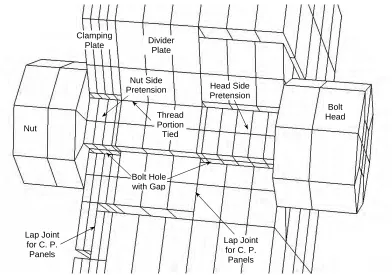
In order to simulate the contact behaviour between different components, 141 contact pairs were defined in the model. Any two surfaces with direct contact or possible contact after deformation had to be identified and defined. For all these contact pairs, sliding with friction (µ = 0.2) was considered. For all contact surfaces without defined gaps, an initial gap of 0.0025 mm (0.0001″) was added to facilitate numerical convergence during analysis. Contacts around one bolt and lap joints are shown in Figure 2. Bolts and bolt holes were modelled as square sections and bolt heads and nuts were modelled as octagons. The bolt sizes in the model were calculated to make their elastic section modulus equal to those of the actual bolts. The gaps between bolts and holes remained as per design. For the threaded portion of a bolt, the nodes for the bolt and hole were tied. Bolt pretension loads were applied to both the head and nut sides of a bolt.
Elastic-plastic material properties for all components were specified in the model. Material properties were determined based on Section II of ASME Boiler and Pressure Vessel Code [1]. True stresses and strains were used in the model to simulate material strain hardening behaviour and component failures were justified based on “true” material failure strains. The following formulae were used to convert engineering stresses and strains to true stresses and strains:
) 1 ln(
) 1 (
eng true
eng eng true
ε + = ε
ε + σ = σ
(1)
Densities for very small elements were increased to reduce running time. This applied only to a few elements and the mass increase for these small elements was negligible to the whole model. Densities for all stationary parts of the model, such as the seat bars and sections of the tubesheet and primary head, were increased irrespective of the sizes of the elements.
The sections of the tubesheet and primary head were considered as elastic foundations for the associated welds and seat bars. The nodes on outer side surfaces of the tubesheet and primary head sections were fixed. Symmetric boundary conditions were applied to the nodes on the symmetric plane. For applying bolt pretensions, lower temperatures were specified for bolt shanks.
Nut
Bolt Head Divider
Plate Clamping
Plate
Lap Joint for C. P. Panels
Lap Joint for C. P.
Panels Thread
Portion Tied
Bolt Hole with Gap
Figure 2 Contacts around a Bolt and Lap Joints Head Side
Pretension Nut Side
hardening occurred in the bolts and other components. Hence, component failure criteria were established based on true plastic strains as follows.
(a) Plastic Strains for Bolts and Welds Membrane plastic strain : εmem < 0.7 εf
Maximum plastic strain : εmax < 0.9 εf
Where εf is the true failure strain of the material.
(b) Plastic Strains for Other Components
They are identical to (a) above provided that the strains are not localised (membrane strains in more than 10% of the width of the component exceed 0.6εf. For a local area, membrane strain limit is 0.9 εf.
ANALYSIS
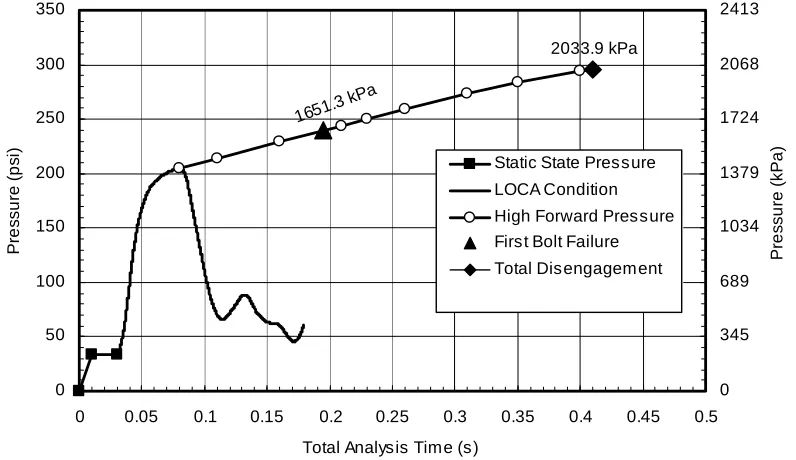
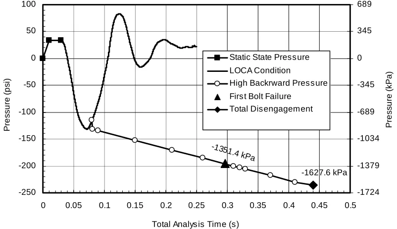
Elastic/plastic dynamic analyses were performed to the model by using ABAQUS/Explicit [3]. The pressure vs. time curves used in the analyses for both the forward and backward directions are shown in Figures 3 and 4. It can be seen that the same analysis procedure was used in the analyses for the both directions, in which pressure loading was applied in three steps as follows.
The first step is to apply a static state pressure of 227.5 kPa (33.0 psi). At the beginning of the step, lower temperatures were applied to all bolts to get bolt pretension loads. An arbitrary expansion coefficient of 1.0E-5 was used for bolt material for applying bolt pretension loads only. For this model, different pretension loads were applied to bolt head and nut sides. It was a time consuming process to find right temperatures to be applied to different bolts to get specified pretension loads for the bolts. Pressure was then ramped up from zero to 227.5 kPa (33.0 psi) in 10 milliseconds (ms) and held for 20 ms to get the model stabilised. At the end of this step, the conditions of the model represent the response to the static state pressure and were used as the initial conditions in the corresponding Thermal-Hydraulic analysis.
Figure 3 Forward Direction Analysis Pressure vs. Time 1651.3
kPa
2033.9 kPa
0 50 100 150 200 250 300 350
0 0.05 0.1 0.15 0.2 0.25 0.3 0.35 0.4 0.45 0.5
Total Analysis Time (s)
Pre
s
s
u
re
(p
s
i)
0 345 689 1034 1379 1724 2068 2413
Pre
s
s
u
re
(k
Pa
)
Static State Pressure
After the static state step, an interactive ABAQUS/Thermal-Hydraulic analysis was carried out for a specified representative LOCA case. In this approach, pressure was applied through the use of ABAQUS user subroutine VDLOAD, in which thermal hydraulic analysis program was incorporated. The deformation and movement of the divider plate were considered in this approach for determining the actual pressure acting on the divider plate under the conditions of the LOCA case.
The coupling of the ABAQUS analysis with the Thermal-Hydraulic analysis was performed by considering each analysis separately for a small time period (0.5 ms) in a step-wise fashion. The Thermal-Hydraulic analysis would provide values of pressure for each of the inlet and outlet chambers on either side of the divider plate during the initial time period immediately following a LOCA event. The ABAQUS analysis would then use this differential pressure across the divider plate as loading for the same time period. The resulting displacement of the divider plate was then presented to the Thermal-Hydraulic analysis as a change in volume for each of the inlet and outlet chambers on either side of the divider plate and the next time period was evaluated. This back and forth communication of differential pressure and resulting displaced volume continued until the Thermal-Hydraulic analysis of the entire LOCA event was completed.
As shown in Figure 3 or 4, the ABAQUS/Thermal-Hydraulic analysis was terminated after the pressure was well passed its peak. The total time for the LOCA analysis step is about 150 ms for the forward direction analysis and 220 ms for the backward direction analysis. For both the LOCA cases, the model was stabilised at the end of the step and the overall deformation of the model was relatively small. Divider plate panels were not disengaged from the seat bars and no component failure was found for both the LOCA cases. The results of each analysis up to the peak pressure were reviewed to ensure that a pressure load vs. displaced volume curve could be extracted that reasonably approximates static loading. This is due to the relatively large back pressure provided by the filled fluid chambers resisting acceleration of the divider plate in the range of LOCA scenarios considered.
The third step is to apply higher static pressure and the step was restarted from a point near the peak pressure for the LOCA analysis step in order to complete the load vs. displaced volume curve. Pressure was increased continuously and slowly until the divider plate panels were disengaged from the seat bars. For the forward direction analysis, the total time for this step was 330 ms. For the backward direction analysis, the total time for this step was 360 ms. During the step, velocity and acceleration of the model were controlled to reduce dynamic influence since this analysis was uncoupled from the Thermal-Hydraulic model. If velocity or acceleration of the model was considered high, pressure would be increased more gradually. From the analysis, displacements, stresses and strains for different components under different pressures and final deformed shapes after disengagement were obtained.
Figure 4 Backward Direction Analysis Pressure vs. Time
-1351.4 kPa
-1627.6 kPa
-250 -200 -150 -100 -50 0 50 100
0 0.05 0.1 0.15 0.2 0.25 0.3 0.35 0.4 0.45 0.5
Total Analysis Time (s)
Pre
s
s
u
re
(p
s
i)
-1724 -1379 -1034 -689 -345 0 345 689
Pre
s
s
u
re
(k
Pa
)
Static State Pressure
LOCA Condition
High Backrward Pressure First Bolt Failure
backward direction analysis, the maximum displacement at the monitor node was 5.08 mm (0.2″). After the peak pressures were passed, the model deformation was less. Hence, deformations for the two LOCA cases were relatively small. At the ends of the LOCA conditions, the divider plate assembly remained intact and engaged with a small amount of plastic strains in the bolts and other components. The maximum plastic strains for the bolts and the seat bars were 2.5% and 3.7%, respectively. The maximum plastic strain for the divider plate and clamping plate was 1%. Based on the failure criteria, there is no component failure for the two LOCA cases.
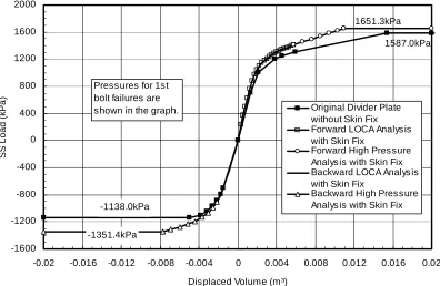
As shown in Figures 3 and 4, first bolt failure occurred under a forward pressure of 1651.3 kPa (239.5 psi) or a backward pressure of –1351.4 kPa (-196 psi). All other components remained below their respective failure criteria under the first bolt failure pressures. The locations of the first failed bolts are indicated in Figure 6. Based on the displacement results for the forward and backward direction analyses, volume changes in the pressure range between the two first bolt failure pressures were calculated. Further volume changes beyond the first bolt failure pressures were not considered. A pressure vs. deformed volume curve was then established and used for safety assessment of the assembly (see Figure 5). In the simplified safety assessment, the fluid/structural response was simulated using a dynamic equation, the pressure vs. deformed volume curve supplied and a conservative failure criterion. Although the results are not as accurate, the improvement in performance (minutes vs. days) allowed for a wide range of additional LOCA scenarios to be considered.
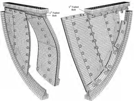
Final deformed shapes (after disengagement of the divider plate) are shown in Figure 6. Deformed shapes, plastic strains and bolt stresses after disengagement were used for loose part assessment of the assembly. After disengagement in both the forward and backward directions, many bolts are failed at one or both sides. However, for both the forward and backward direction disengagement, there are enough bolts, which did not failed at nut sides, available to keep the clamping plate panels and skin panels attached to the divider plate panels. After disengagement, plastic strains for all other components (except bolts) are below their limits, except for a few local hot spots, and the damages of the hot spots are local. Hence, no new loose parts are generated due to the addition of the clamping plate and the skin in the divider plate modification.
Figure 5 Pressure Load vs. Displaced Volume Curves
1587.0kPa
-1138.0kPa
1651.3kPa
-1351.4kPa -1600
-1200 -800 -400 0 400 800 1200 1600 2000
-0.02 -0.016 -0.012 -0.008 -0.004 0 0.004 0.008 0.012 0.016 0.02
Displaced Volume (m³)
SS
L
o
a
d
(k
Pa
)
Original Divider Plate without Skin Fix Forward LOCA Analysis with Skin Fix
Forward High Pressure Analysis with Skin Fix Backward LOCA Analysis with Skin Fix
Backward High Pressure Analysis with Skin Fix Pressures for 1st
CONCLUSIONS
Based on the analyses, the modified divider plate assembly can withstand higher pressure loads in both forward and backward directions. No new loose parts are generated due to the divider plate modification. The analysis approach has also been used to justify design modifications for several other divider plate assemblies with “skin fix”.
REFERENCES
1. ASME, Boiler and Pressure Vessel Code, Section II, “Material Specifications,” 1995 Edition.
2. ASME Boiler and Pressure Vessel Code, Section III, “Rules for Construction of Nuclear Vessels,” 1995 Edition. 3. Hibbit, Karlsson & Sorensen, Inc, (1998). “ABAQUS/Explicit User’s Manual Version 5.8,” USA.
Figure 6 Deformation Shapes after Disengagement 1st Failed
Bolt
1st Failed Bolt
Under Forward Pressure Under Backward Pressure