Determination of Fracture Parameters of High
Performance Concrete
Sidhardhan S1, Jansi sheela.S 2
,
Associate Professor, Department of Civil Engineering, Government College of Engineering, Tirunelveli, India1
Assistant Professor, Centre for Rural Technology, The Gandhigram Rural Institute, Dindigul, India2
ABSTRACT: High Performance Concretes (HPC) are concretes with properties or attributes which satisfy the performance criteria. Generally, concretes with higher strengths and attributes superior to conventional concretes are desirable in the construction industry. HPC is defined in terms of Strength and Durability. Application of high performance concrete has got momentum in various fields of construction globally in the near past. HPC is being practiced in the fields like construction of nuclear reactors, runways at airport, railway sleepers, cooling towers, silos, chimneys and all kinds of bridges. HPC, using admixtures, microsilica and other supplementary cementing materials such as flyash makes concrete easier to place, stronger and more durable than normal strength concrete. When applied to design, understanding the cracking behaviour requires the use of a modern method of structural analysis namely Fracture Mechanics. Fracture Mechanics also provides powerful criteria for the prediction of crack initiation and propagation. The improved pore structure of HPC is achieved by the use of mineral admixtures such as microsilica and flyash causes densification of paste- aggregate transition zone, which in turn affects the fracture characteristics. The objective of this project is to study the fracture behaviour of HPC element. In this study, a wide range of concrete mixes have been designed to vary the strength of concrete by changing the percentage of microsilica and fly ash. The fracture behavior of high performance concrete using microsilica and flyash by making beam of size 500 mm × 100 mm × 100 mm is to be investigated. In this project the analysis of the beam in ANSYS have been done and the corresponding fracture parameters are obtained and also the preliminary investigations of the material properties have been done.
KEYWORDS: High Performance Concrete, Micro silica, Fracture Mechanics, microsilica, fracture parameter.
I. INTRODUCTION
continues. Fracture mechanics deals with the mechanical responses of a cracked body subjected to the application of forces or stresses.
HIGH PERFORMANCE CONCRETE
American Concrete Institute (ACI) defines High Performance Concrete (HPC) as ―Concrete meeting special combinations of performance and uniformity requirements that cannot always be achieved routinely using conventional constituents and normal mixing, placing and curing practices‖. Important governing factors for HPCs are
strength, long term durability, serviceability as determined by crack and deflection control, as well as response to long term environmental effects. High Performance Concretes (HPC) are concretes with properties or attributes which satisfy the performance criteria. Generally, concretes with higher strengths and attributes superior to Conventional concretes are desirable in the Construction Industry. HPC is defined in terms of Strength and Durability.Therefore HPC can be considered as a logical development of cement concretes in which the ingredients are proportioned and selected to contribute efficiently to the various properties of cement concrete in fresh as well as in hardened states. Since less mixing water is required in HPC than in normal strength concrete for the same workable concrete consistency, a lower porosity is developed in HPC which also produces higher compressive strengths.
COMPOSITION OF HPC
The ingredients of HPCs are almost same as those of Conventional Cement Concretes (CCC). But, because of lower Water Cement Ratio, presence of Pozzolans and chemical admixtures etc., the HPCs usually have many features which distinguish them from CCCs. From practical considerations, in concrete constructions, apart from the final strength, the rate of development of strength is also very important. The High Performance Concrete usually contains both pozzolanic and chemical admixtures. Hence, the rate of hydration of cement and the rate of strength development in HPC is quite different from that of CCC.
BASIC CONCEPTS OF LINEAR ELASTIC FRACTURE MECHANICS (LEFM)
Cracking is an essential feature of the behavior of concrete structures. Even under service loads, concrete structures are normally full of cracks. Clearly, cracking should be taken into account in predicting ultimate load capacity as well as behavior in service. Fracture researchers have at the present no doubt that the introduction of fracture mechanics into the design criteria for all brittle failures of reinforced concrete structures (such as diagonal shear, punching shear, torsion or pull out, or for concrete dams), can bring about significant benefits. It will make it possible to achieve more uniform safety margins, especially for structures of different sizes. This, in turn, will improve economy as well as structural reliability. It will make it possible to introduce new designs and utilize new concrete materials. Fracture mechanics will be particularly important for high strength concrete structures, fiber- reinforced concrete structures, concrete structures of unusually large sizes, and for prestressed structures. The application of fracture mechanics is most urgent for structures such as concrete dams and nuclear reactor vessels or containments, for which the safety concerns are particularly high and the consequences of a potential disaster enormous.Facture mechanics is concerned with the qualitative description of the mechanical state of a deformable body containing a crack or cracks with a view toward characterizing and measuring the resistance of materials to crack growth . It is a relatively new area of solid mechanics research, with its foundation laid in the late 20th century. Already it has broad application in systems ranging in size from micrometer length scales ( thin films) up to kilometer length scales ( earthquake fault lines). Fracture mechanics deals with the mechanical responses of a flawed or a cracked body subjected to the application of forces or stresses. For certain cracked configurations subject to external forces, it is possible to derive closed- form expressions for the stresses in the body, assuming isotropic linear elastic material behavior.Fracture behavior can be classified into three basic types (Fig 4.1), each associated with a local mode of deformation. Mode I, or the opening mode, where the principal load is applied normal to the crack plane, tends to open the crack. Mode II, or sliding mode, corresponds to in-plane shear loading and tends to slide one crack face with respect to the other. Mode III, or the tearing mode, refers to out-of-plane shear. A cracked body can be loaded in any one of these modes, or a combination of two or three modes.
important in fracture testing and application except for testing of adhesive joints. Mode-I causes the crack to open orthogonal to the local fracture surface and results in tension or compressive stresses on surfaces. Mode-II causes the crack surfaces to slide relative to each other in the x1 direction and results in shear stresses in the x2 direction ahead of the crack. In mode III or tearing mode, the body is loaded by shear forces parallel to the crack surfaces and the crack surfaces slide over each other in the z direction the deformations are then skew symmetric with respect to the plane perpendicular to the z and y-axes.
Fig.1 Modes of Fracture
II. METHODOLOGY
To investigate the fracture parameters of the high performance concrete beam of size 500 mm × 100 mm × 100 mm for varying notch sizes with notch height to beam height ratio (a0/d) between 0.1 - 0.3 and tested under three point
bending test. The schematic representation of three point bending test is represented in Fig 2.
Fig.2 Three Point Bend Test
NUMERICAL ANALYSIS
ANSYS is general-purpose finite element analysis (FEA) software package. Finite Element Analysis is a numerical method of constructing a complex system into very small pieces called elements. The software implements equations that govern the behavior of these elements and solves them all; creating a comprehensive explanation of how the system acts as a whole. These results then can be presented in tabulated or graphical forms. This type of analysis is typically used for the design and optimization of a system for too complex to analyze by hand. Systems that may fit into this category are too complex due to their geometry, scale, or governing equations. The product offers a complete set of elements behavior, material models and equation solvers for a wide range of engineering problems.
rely heavily on empirical formulas for the design of concrete structures, which were derived from numerous experiments. With the advent of digital computers and powerful methods of analysis, such as the finite element method, many efforts to develop analytical solutions which would obviate the need for experiments have been undertaken by investigators. The finite element method has thus become a powerful computational tool, which allows complex analyses of the nonlinear response of concrete structures to be carried out in a routine fashion. With this method the importance and interaction of different nonlinear effects on the response of concrete structures can be studied analytically.
CALCULATING FRACTURE PARAMETER
In this analysis the model is considered as plane strain problem. Once the static analysis is completed, the POST1 command, the general postprocessor can be used to calculate the fracture parameters. As mentioned earlier, typical fracture parameter of interest is stress intensity factor. Fracture process zone in concrete results from microcracking and aggregate interlock around the crack tip. The size of this process zone is likely to depend on the size of aggregates, the debonding characteristics of aggregates as well as specimen geometry. During the crack propagation, the crack growth is affected by environmental conditions, material properties, and loading conditions including the magnitude and stress ratio of overload. Careful attention must be given to a series of critical decisions about element type, mesh method (Mapped mesh, Free mesh), element length size, the selection of material behaviors, model design (geometry of the specimen, symmetric boundary condition or loading condition) and crack tip modelling (singular point) if the analysis is to be reliable
(a) (b)
Fig.3 (a) Model of Concrete beam (b) Meshed model of concrete beams
ANALYTICAL RESULTS
(a) (b)
(c) (d)
(e) (f)
(g) (h)
Stress Intensity Factor of HPC B1 Stress Intensity Factor of HPC B2
Stress Intensity Factor of HPC B3 Stress Intensity Factor of HPC B4
In LEFM the stress intensity factor ‘K’ is the relevant fracture parameter to characterize the stress and strain fields around the crack tip, as originally described by Irwin. Under mode I (crack-opening) loading ‗KI’ may be compared
with a material's fracture toughness ‗KIC’ Inorder to predict the stability of a crack. To compute KI with the finite
element method (FE) quarter-point crack-tip elements were introduced by Barsoum.
III. RESULT AND DISCUSSION
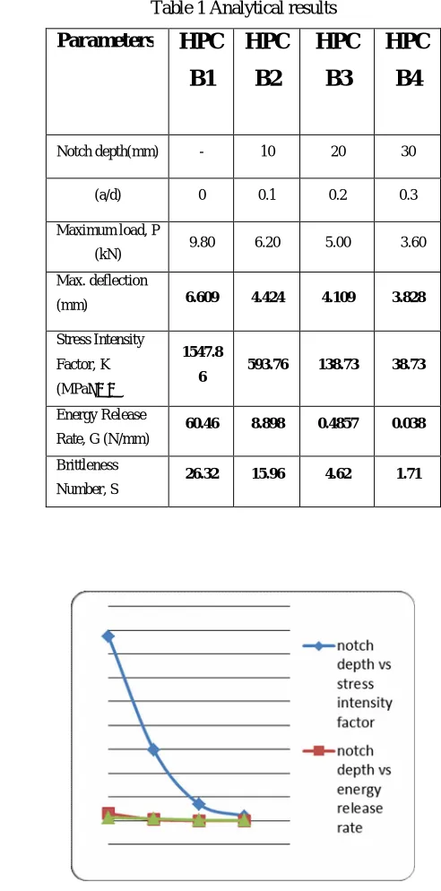
Table 1 Analytical results
\
Fig.4 Analytical results
it is observed that all the parameters depends on the notch depth. The mid span deflection decreases proportionally in accordance with the (a/d) ratio
Parameters
HPC
B1
HPC
B2
HPC
B3
HPC
B4
Notch depth(mm) - 10 20 30
(a/d) 0 0.1 0.2 0.3
Maximum load, P
(kN) 9.80 6.20 5.00 3.60
Max. deflection
(mm) 6.609 4.424 4.109 3.828
Stress Intensity
Factor, K
(MPa√mm)
1547.8
6 593.76 138.73 38.73
Energy Release
Rate, G (N/mm)
60.46 8.898 0.4857 0.038
Brittleness
Number, S
IV. CONCLUSION
The finite element analysis gives a first estimation of fracture parameters. All the fracture properties of M60 mix beam depends on the (a/d) ratio .When the (a/d) ratio increase the values of K, G,S decreases . The large amount of reduction in values for a small increase in(a/d) ratio may be due to the presence of fly ash in concrete. These behaviors have to be further verified by experiments on already casted beams.
REFERENCES
[1] Praveen kumar and Kausik, S.K, ―Some trends in the use of concrete”,The IndianConcrete Journal
[2] ASTM E 399 ― Standard Method for Plane Strain Fracture Toughness of Metallic Materials‖ ASTM, Annual Book of Standards,
Vol. 03.01.
[3] Barbhuiya,S.A, Gbagbo, J.K, Russell, M.I, Shweta Goyal and Basheer, P.A.M.(2009) Properties of fly ash concrete modified with hydrated lime and silica fume‖, Construction and Building Materials, Vol 23,3233-3239 .
[4] David Roylance (2001), ―Introduction to Fracture Mechanics”, Department of Materials Science and Engineering, Massachusetts Institute of Technology, Cambridge.
[5] Ravindra Gettu,Bazant, Z.P and Martha E.Karr (1990), ―Fracture properties and brittleness of high strength concrete‖, ACI Material Journal.
[6] Dale ,P. Bentz, Andrew ,S. Hansen,J, Jung- Heum Yon and John, M. Guynn(2011), ―Optimization of cement and fly ash particle sizes to produce sustainable concretes‖, Cement and Concrete Composites,Vol 33,824-831.
[7] Luiz Eduardo,T, Ravindra Gettu, Pusit Lertwattanaruk and Tulio, N, Bittencourt (2000), ―Study of crack propagation in the specimen recommended by Rilem TC 162 based on linear elastic fracture mechanics‖.
[8] Raghu Prasad, B.K, Patnaik, R and Appa Rao, G (2001), ―Influence of Strength on the fracture energy of HPC‖.
[9] Bharatkumar,B.H, Raghuprasad,B.K, Ramachandramurthy,D.S and Narayanan,R (2005), ―Effect of flyash and slag on the fracture characteristics
of high performance concrete‖, Materials and Structures.
[10] Bezerra, E.M, Joaquim,A.P, Savastano,H, John,V.M and Agopyan, V (2006), ―The effect of different mineral additions and synthetic fiber
contents on properties of cement based composites‖,Cement andConcrete Composites555-563.