Vol. 4, Issue 2, February 2015
Numerical Optimization of Cold Formed
Closed Built-up Steel Column
Pradeep T
1, Arun N
1P.G. Student, Department of Civil Engineering, K.S.Rangasamy College of Technology, Tiruchengode, Namakkal
Tamil Nadu India1
ABSTRACT: The Optimization of cold formed closed steel built-up columns without stiffeners is performed using finite element analysis. An accurate finite element model is used for study in which different size of webs are investigated. The closed cold formed built-up steel column strength were studied with and without coupling of section. The finial section of column buckling behaviour is predicted by the nonlinear finite element method anddiscusses the unfactored design column strength.
KEYWORDS: Channel section, Built-up section and Optimized specimen. I. INTRODUCTION
In steel structures, two primary structural steel member types are used: Hot rolled steel members and Cold- forming steel members. The Hot rolled steel members are formed at elevated temperature whereas Cold formed steel are formed at room temperature. The Hot rolled section are heavy weight instead of this, Cold formed steel are less weight. Cross sectional shapes are formed to close tolerances and these can be consistently repeated for as long as required. Cold rolling can be employed to produce almost any desired shape to any desired length. It is possible to displace the material far away from the neutral axis in order to enhance the load carrying capacity.
Cold-formed steel sections are widely used in construction and building industries. The popularity of these products has dramatically increased in recent years due to their wide range of application, ease of fabrication and high strength-to-weight ratios. Cold-formed steel structural members may lead to a more economic design than hot-rolled steel members. Cold-formed steel members are either cold-rolled or brake-pressed into structural shapes. Channel section is a common type of Singly-symmetric section. Cold-formed steel channels are commonly used as wall studs and chord members of roof trusses in steel frame housing and industrial buildings. These structural members are mainly subjected to axial compression. The compression members may fail in complex buckling modes, such as local, distortional, flexural and flexural-torsional buckling.
II. NUMERICAL INVESTIGATION The main scope of the study is as follows:
To examine the effect of strength in cross sectional geometries on thecold-formed steel built-up section by
using the finite element analysis software ANSYS 12.
To choose the Best channel closed built-up section.
III. SELECTION OF SECTION
Vol. 4, Issue 2, February 2015
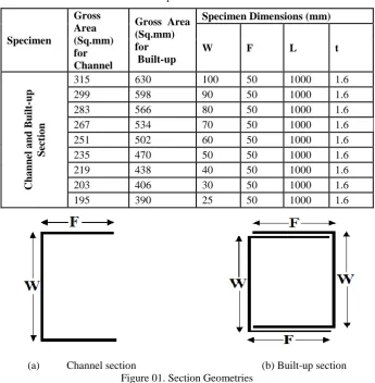
Table 01. Specimen Dimensions
(a) Channel section (b) Built-up section
Figure 01. Section Geometries
The Torsional strength of column are identified using linear Finite element analysis software (CUFSM). The figure 02 shows the curve for load factor and length of the section. The torsional failure is occur in 1000mm of the length , this is the problem to rectified.
Figure 02. Length from CUFSM result
Specimen
Gross Area (Sq.mm) for Channel
Gross Area (Sq.mm) for Built-up
Specimen Dimensions (mm) W F L t
Cha
nn
el
a
nd
B
uil
t-up
Sect
io
n
315 630 100 50 1000 1.6
299 598 90 50 1000 1.6
283 566 80 50 1000 1.6
267 534 70 50 1000 1.6
251 502 60 50 1000 1.6
235 470 50 50 1000 1.6
219 438 40 50 1000 1.6
203 406 30 50 1000 1.6
Vol. 4, Issue 2, February 2015
IV. FINITE ELEMENT MODEL
Finite element analysis plays an important role in engineering practice, as it is relatively in expensive and time efficient compared with physical experiments, especially in parametric study of cross section geometry is involved. Finite element analysis software package ANSYS 12 is used to simulate the buckling behaviour of the intermediate length cold-formed steel cold-formed steel stiffened sigma section under axial compression. Four-noded SHELL 181 elements are used in the finite element analysis. Material and geometric nonlinearity are incorporated in the developed finite element model whereas residual stresses and cold-forming effects are not included in the finite element model. The models are based on the centre line cross section dimensions. A series of mesh convergences studies are carried out, a mesh size of 10 mm X 10 mm are found to be suitable for the column length of 1000 mm. The Detailed Finite element model including mesh size and support conditions are illustrated in Figure 03.
In this study pin end conditions are used as shown in Figure 03(c) to Figure 03(d). At the unloaded end, translations in all the directions are restrained as well as the rotation about the longitudinal direction. But in the loaded end is restrained as same as that of the unloaded end except for the translation in the longitudinal direction. All the boundary conditions are applied to the independent centroidal node of the rigid fixed point created at the loaded and unloaded end of the model defined as the master nodes .This master node acts as a rigid surface that was rigidly connected to both ends of the column as shown in Figure 1d. All the sections are of thickness 1.6 mm with yield stress of 270
N/mm2, Young’s modulus of 2 X 10⁵ N/mm2 and Tangent modulus of 20000 N/mm2 with a Poisson’s ration of 0.3. The
local-distortional imperfection is taken as approximately equal to the plate thickness as recommended by Schafer and Pekoz.
Two types of analyses are used in the finite element analysis for buckling. Initially a linear elastic buckling analysis is performed to obtain the buckling loads and associated buckling modes. Finally, non linear buckling analyses are performed to predict the ultimate load capacity.
Vol. 4, Issue 2, February 2015
V. NUMERICAL RESULTS AND DISCUSSION
Cold formed steel section of suitable dimension is generated in the analysis software ANSYS 12. The Non-linear Load and Deflection for all the sections were predicted from finite element analysis software (ANSYS 12). The investigation is carried out by developing the model of the order of the relation between web (W) and flange (F), (W=2F to F=2W). The same study was carried in the closed built-up steel channel column. The Load and Deflection of each section of both open channel and closed built-up channel where shown in Table 02.
Table 02. Load and Deflection of Sections
Specimen Depth (W) in mm Load (P) in Kn Deflection
(Y) in mm Specimen
Load (P) in Kn
Deflection (Y) in mm
Pb Pc Yb Yc Cha nn el Sect io n
100 27.925 1.392
B uil t-up Sect io n
87.607 0.928 3.137225 0.666667
90 26.435 1.395 87.907 0.947 3.325402 0.678853
80 24.611 1.398 86.477 0.978 3.513754 0.699571
70 23.284 1.299 84.976 1.003 3.649545 0.772132
60 21.978 1.327 82.547 1.0378 3.755892 0.782065
50 21.015 1.3768 79.69 0.1151 3.792053 0.0836
40 19.397 1.445 69.849 1.1518 3.601021 0.797093
30 20.292 0.8689 43.91 0.8871 2.163907 1.020946
25 14.637 0.9726 33.515 0.678 2.289745 0.697101
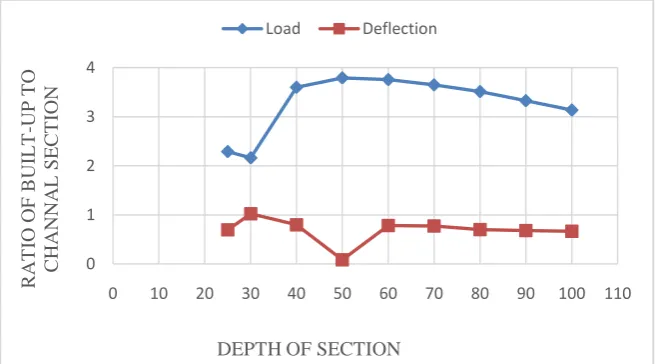
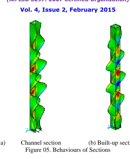
The Nonlinear analysis model were developed for all the sections, which were optimized form graph. The graph were drawn from the table 02, in the X axis have depth of section and Y axis have Load and Deflection ratio of built-up to channel sections as shown in figure 04. The optimized closed built-up section have good strength and less deflection are shown in graph, the depth of section having 50mmX50mm (W=F). The nonlinear finite element model were developed for optimized closed built-up section are shown in figure 05 in different manner. And the optimized section were compared with placing of open section in different manner.
Figure 04. Depth vs. Load and Deflection ratio
0 1 2 3 4
0 10 20 30 40 50 60 70 80 90 100 110
R A T IO OF B UI L T -UP T O C HA NNA L SECT ION
DEPTH OF SECTION
Vol. 4, Issue 2, February 2015
(a) Channel section (b) Built-up section
Figure 05. Behaviours of Sections
VI.CONCLUSION
Finite element analysis of the cold formed closed built-up column member is analysed using ANSYS 12 software. The nonlinear strength and deflections were predicted from above research, for each cross sections and developed the relations between the built-up and channel sections. The sections were optimised from the finite element result. Finally the section had been confirmed and the behaviour of both the sections have been studied.
REFERENCES
1. Ben Young, ―Research on cold-formed steel columns‖, Thin-Walled Structures Vol; 46 pp,731–740, 2008.
2. Teng, J.G., Yao J, Y. Zhao, ―Distortional buckling of channel beam-columns‖, Thin-Walled Structures Vol; 41pp, 595–617, 2003.
3. Beregszaszi Z, Adany S, ―Application of the constrained finite strip method for the buckling design of cold-formed steel columns and beams via the direct strength method‖, Journal of Computers and Structures,Vol; 89, pp.2020–2027,2011.
4. Narayanan S, Mahendran M, ―Ultimate capacity of innovative cold-formed steel columns. Journal of Constructional Steel Research‖, Vol; 59, pp,489–508, 2003.
5. Nguyen V.B., Wang C.J., Mynors D.J., English M A, Castellucci M A, ―Compression tests of cold-formed plain and dimpled steel columns‖ Journal of Constructional Steel Research Vol; 69,pp,20–29, 2012.
6. Shanmugam N.E., Dhanalakshmi M., ―Design for openings in cold-formed steel channel stub columns‖, Thin-Walled Structures,Vol; 39, pp, 961–981,2001.
7. Alia M.AL., Tomkoa M., Demjana I., Kvočáka V., ―Thin-walled cold-formed compressed steel members and the problem of initial imperfections‖, Steel Structures and Bridges Vol; 40, pp,8 – 13,2012.
8. BatistaE. M. andRodriguesF. C., ―Buckling Curve for Cold-Formed Compressed Members‖, Journal of Constructional steel research, Vol.28, pp.121-136, 1994.
9. SchaferB.W. and Peko¨z T., ―Computational modeling of cold-formed steel: characterizing geometric imperfections and residual stresses‖, Journal of Constructional steel research, Vol.47, pp.193-210, 1998.
10. Ben Young., ―Design of channel columns with inclined edge stiffeners‖, Journal of Constructional Steel Research, Vol.60, pp. 183–197, 2004. 11. Jintang Yan and Ben Young ―Numerical investigation of channel columns with complex stiffeners—part I: test verification‖, Thin-Walled
Structures, Vol.42, pp.883–893, 2004.