Vol. 4, Issue 7, July 2015
A Proposal of an Autonomous Voltage
Regulator Controller to Apply with Future
Superconductor Distribution Networks
Mustafa Ali Elsherif 1, Ahmed A. Baaiu2, Elfadil Z. Yahia3
Lecturer, Department of Electrical Engineering, Faculty of Engineering, Misurata University, Libya 1
Assistant Professor, Department of Electrical Engineering, Faculty of Engineering, Misurata University, Libya 2
Assistant Professor, Department of Electrical Engineering, Faculty of Engineering, Misurata University, Libya3
ABSTRACT: Implementing superconductor technologies in the distribution networks can eliminate the voltage regulation and power losses issues that face the conventional networks, however, the impedance of superconductor distribution networks is very small which causes a very small changes in voltage magnitude. Nevertheless, the conventional control technologies implemented with the conventional distribution networks are relied on the voltage changes magnitude in the network. This would be a serious issue for the future superconductor distribution networks where a very small voltage change magnitude occurs. Therefore, this paper introduces a proposal of autonomous voltage regulator (AVR) which can be implemented with the future superconductor distribution networks to control shared reactive power between distribution generators and then compared with the conventional AVR that is used with the conventional distribution networks. Additionally, the on load tap changer transformer has modelled with a such network to maintain voltage within limits in peak demands.
KEY WORDS: AVR controller; on-load tap-changer transformer controller; control reactive power; control voltage level; superconductor distribution network.
I. INTRODUCTION
Growing challenges relating to voltage control, power losses and demand increases in urban areas which are supplied by medium voltage (MV) distribution networks highlights the need to accurately and flexibly share reactive power provision between large power stations and multiple distribution generators[1]. Consequently, controlled voltage of conventional distribution networks can be achieved with distribution generators (DGs) using a reactive power supplying approach [1].Moreover, other advantage can be gained from controlling sharing reactive power between DGs is low carbon considerations and generation economics for the distribution networks[2].The voltage drop in the distribution networks can be approximated by following equation 1.
∆V = RP +XQ
V ± j
XP −RQ
V (1)
Where, ∆V is the voltage change in the system from sending to receiving end busbars; P and Q are the active and reactive power loads; R and X are resistance and reactance respectively and V is the sending end voltage.
at 77 K, while the reactive power losses in superconductor distribution networks are caused by reactance of HTS cables that effect on voltage change magnitude in the network. The total real and reactive power loss in a distribution network can be determined by equations 1 and 2.
i N
i i
loss
I
R
P
1 2
(2)
i N
i i
loss
I
X
Q
1 2
(3)
Where R is the resistance, X is the reactance, I is current and N number of lines.
However, in superconductor distribution power systems the voltage magnitude change, which cases by reactive power losses, is approximately 10 times smaller than the voltage magnitude change occurs in conventional distribution network [6]. This raises the question that is addressed by this paper namely to what extent can conventional AVRs be applied to superconductor power systems to control and share reactive power in the absence of relatively large voltage changes?. Thus, this paper aims to investigate the possibility of controlling reactive power in a MV superconductor distribution network through conventional AVRs. Moreover, a new proposal of AVRs is presented for future MV superconductor distribution networks in order to reduce the cost of AVRs in the future.
Nomenclature
AVR Automatic voltage regulator HTS High-temperature superconductor MV Medium voltage
DG Distribution generator SB Slack bus
BT Bus transformer B Bus bar
Vref Voltage reference OLTC On-load tap-changer LDC Line drop compensator PMS Power management system AIR Automatic current regulator AQR Automatic reactive regulator
II. CASE STUDY
Vol. 4, Issue 7, July 2015
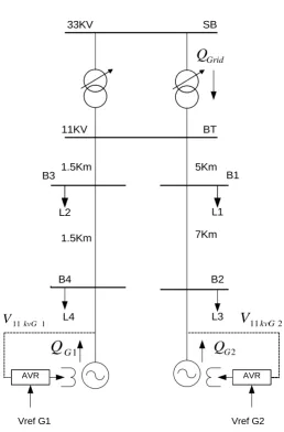
Fig. 1 Conventional distribution network
III.CONVENTIONAL GENERATOR AVR MODEL
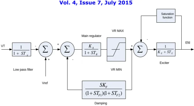
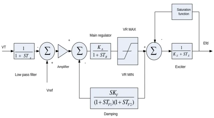
It is useful to explain how conventional generator AVR works. Figure 2 shows the generator AVR model, IEEE type2 which uses in this study. The main function of a synchronous generator excitation system is to regulate the voltage of the generator terminal voltage. The excitation of the generator can be adjusted using an AVR which will operate continuously to adjust the excitation of the generator, and in turn, impact the terminal voltage and reactive power exchanged with the network. The function of the generator AVR in this study is to keep the terminal voltage at 11 kV equal to the reference value (Vref). Therefore, the reactive power output from the generator is changed in line with the terminal voltage of 11 kV. The approach of the generator AVR model was taken from [9], which was modeled on IEEE type 2[10]. Figure 2 shows the AVR modelled on IEEE type 2, all the parameters values of the model are given in Appendix.
AVR AVR
SB 33KV
BT 11KV
B1
B2 B3
B4
7Km
1.5Km 5Km
1.5Km
L1 L2
L3 L4
Vref G1 Vref G2
Grid
Q
2
G
Q
1
G
Q
2
11kvG
V
1g
ST
1 1
E E ST
K
1
R A ST K
1
) 1 )( 1
( F1 F2
F
ST ST
SK
Damping Low pass filter
Main regulator
Exciter VR MAX
VR MIN
Efd
Vref VT
+
+ +
-Fig. 2 The generator AVR model, IEEE type 2
IV.MODELLING OF THE ON LOAD-TAP CHANGER TRANSFORMER CONTROL SYSTEMS
Modelling of the transformers with tap-changing facilities is achieved using Matlab Simulink by modelling the transformer to control the tap ratio of the 33 kV/11 kV transformer. The model for the control systems is used to change automatically the transformer taps under load in order to keep the voltage in the secondary side of the transformer within the required limit. This process can be achieved using a line drop compensator (LDC). The function of the line drop compensator (Rc+jXc) is to control the voltage at the remote point of stand-alone feeder. The magnitude of the resulting compensated voltage (Vc) which is fed to the AVR, is given by equation 4.
t c c t
c
V
R
jX
I
V
(
)
(4)
Where Vt is the measured phasor voltage at the transformer secondary side, and It is the current through the transformer.
The measured voltage (VBT) is compared with the reference voltage (Vref) to obtain the error as shown in equation 5.
BT ref
V
V
Error
(5)Two transformers are combined into one transformer by calculating their impedances in parallel. The On-Load Tap-Changing (OLTC) of the transformer control system model is shown in Figure 3. The tap-changing steps move in positive and negative directions to adjust the secondary voltage of the transformer. The change of tap position is carried out in discrete steps with each beginning at 1.67% of the normal ratio. The control system will be operated if the error is greater than a deadband of 1% tolerance band (in which case the tap position moves down one step) or less than -1 of tolerance band % (in which case the tap position moves up one step) in order to maintain the voltage in the distribution network within ±0.06 pu. The control system of the OLTC of the transformer begins to work after 30 seconds and once the tap position is set, it is held there for 10 seconds before the next change of tap position can take place [9]. The number of steps that can be made is ± 20 steps [10].
Vol. 4, Issue 7, July 2015
Fig. 3 On-load tap-changing transformer model
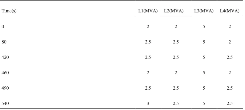
A variable loads has modelled in the simulation to investigate how the change in supplying reactive power will affect generator AVRs response and their reactive power sharing. Following Table introduces how loads are changed in the simulation. The locations of such loads which are shown in figure 1, based on the time the loads are changed. For example, the peak demand is 13MVA at 540s while the demand is 12MVA at 80s.
Table 1: Variable loads in the case study distribution network
L4(MVA) L3(MVA)
L2(MVA) L1(MVA)
Time(s)
2 5
2 2
0
2 5
2.5 2.5
80
2.5 5
2.5 2.5
420
2 5
2 2
460
2.5 5
2.5 2.5
490
2.5 5
2.5 3
540
Results and Discussions
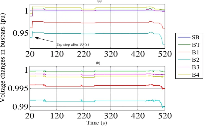
In order to provide a baseline case for the study it is necessary to evaluate the performance of generator AVRs in conventional and superconducting networks to achieve sharing reactive power. This will identify if the controller of the transformer tap changer with a variable Vrefs for the generator AVRs can maintain the voltage levels within required limits (± 6%) with sharing reactive power in this 11kV distribution network. Consequently, the first step of this investigation is to see if the transformer tap can keep voltage within limits when Vrefs for each generator AVR is at 0.94 pu in both the 11 kV conventional and superconductor distribution networks. Based on results indicated in figure 4, the voltage levels in busbars B1, B2, B3 and B4 in both cases are changed as loads (L1, L2, L3 and L4) in the network change. The locations of loads and busbars in the network are shown in figure 1. Figure 4 (a and b) shows the results of
Error
VBT
Vref
Tap-changer
UP DOWN
Time delay
Deadband
+ -
Regulator pointAVRs. Moreover, figure 4 (a) shows that for the 11kV conventional network the tap transformer stepped up once at 30 (s) to maintain the voltage level within limits in the network because voltage level dropped in B2 when total demand was 11MVA. However, the voltage level also dropped below the limit of -6% at B2 when total demand was 12.5MVA at 500s as shown in figure4 (a).The tap transformer could not maintain the voltage level within the required limit in B2 at 500s for the 11kV conventional distribution network. This is because the control of the transformer tap changer is only operated if the error is greater or less than a deadband ±1%. In the 11kV superconductor network the transformer tap was not required even at 500s, when total demand was 12.5MVA,to operate because all of the voltage deviations were within the deadband limits (±1%) As shown in figure 4(b).
Fig. 4 (a) Results of voltage changes in conventional distribution network (b) Superconductor distribution network
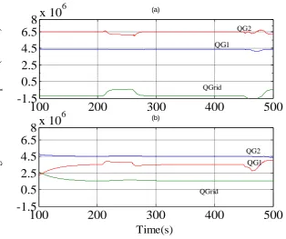
Another test was carried out on the 11 kV conventional and superconductor distribution networks with the generator AVRs at different values of Vrefs. The Vref forDG1 AVR was 1.002 pu while the Vref for DG2 AVR was 1.005 pu. Figure 5 (a and b) shows the results of reactive power output from the grid and DGs in 11 kV superconductor and conventional distribution networks.
Based on the results in figure 5, the amount of reactive power which has been provided by each DG in 11 kV conventional distribution networks was different from the amount of reactive power which produced from DGs in the 11 kV superconductor distribution network. This was because the voltage changes in the 11 kV superconductor distribution network were very small in comparison to the voltage changes in the 11 kV conventional distribution network. Different voltage changes in such networks have a major influence on the amount of reactive power which can be produced from DGs for example in figure 4 the voltage changes at 300s occurred at B2 which was connected to DG2 in the 11kV conventional distribution network and was approximately 10 times higher than the voltage change at B2 which was connected to DG2 in the 11kV superconductor distribution network under the same condition. Therefore, the DG2 in the 11kV conventional distribution network provided higher reactive power (6.5MVArs) at 300s, when total demand was 12 MVA while DG2 in the 11kV superconductor distribution network provided lower reactive power (4.5MVArs) to the network for the same condition.
20
120
220
320
420
520
0.95
1
(a)
20
120
220
320
420
520
0.99
0.995
1
Time (s)
(b)
V
o
lt
ag
e
ch
an
g
es
i
n
b
u
sb
ars
(p
u
)
SB BT B1 B2 B3 B4
Vol. 4, Issue 7, July 2015
Fig. 5 (a) Results of Q (MVARs) conventional distribution network (b) Superconductor distribution network (vref1.005 and 1.002 pu)
Moreover, the errors occur in AVRs controller when superconductor network is considered are 100 times smaller than the errors occur in AVRs controller when conventional network is used. In this case, the implementing power management systems (PMS) controllers is necessary use to supervise the generator AVRs and transformer tap to provide the optimal percentage of reactive power desired at a certain time and to keep the voltage within the required limit of ±6% in each distribution network However, this paper focus on introduced a proposal of AVRs which can be implement with future superconductor distribution networks for controlling reactive power sharing.
V. A NEW PROPOSAL OF AVR FOR FUTURE SUPERCONDUCTOR DISTRIBUTION NETWORKS
Based on results, the voltage changes occur in the 11 kV superconductor distribution network are 10 times smaller than voltage changes occur in the 11kV conventional distribution network. Thus, the errors in AVRs when the 11 kV superconductor distribution network are approximately 100 times smaller than errors occur in the 11 kV conventional distribution network. The conventional traditional AVR cannot be implemented in superconductor distribution networks because the conventional AVRs will be challenged to operate with very small errors. Based on results, using a very sensitive amplifier in conventional AVRs with future superconductor distribution networks is necessary for make errors larger enough for conventional AVRs. Thus, the price of AVRs will be increased as a new component need to be install in AVRs for using with superconductor networks. A new design of AVRs needs to be achieved for future superconductor distribution networks. Because the voltage is no longer need to be controlled in superconductor distribution networks, new electrical measurement quantities need to be measured from grid instated at terminal voltage of generators. At the moment there are two aspects to achieve controllers, automatic current regulator (AIR) and automatic reactive regulator (AQR). AIR will be measured the current in generator basbar while AQR will be measured the reactive power in generator basbar. This leads to create new close loops in automatic generator controller, which may be reduced the price of automatic generator controllers. Figure 6 demonstrates a modified of AVRs for future superconductor distribution networks.
100
200
300
400
500
-1.5
0.5
2.5
4.5
6.5
8
x 10
6 (a)
100
200
300
400
500
-1.5
0.5
2.5
4.5
6.5
8
x 10
6Time(s)
G
ri
d
a
n
d
g
en
er
at
o
rs
r
ea
ct
iv
e
p
o
w
er
(
M
V
A
rs
)
(b)
QG2 QG2
QG1
QGrid
QG1
Fig. 6 The modified generator AVR
VI.CONCLUSION
In this paper, control of the reactive power contributions of power feeders between two distributed generators connected to 11 kV conventional distribution network was presented based on an automatic voltage regulator. The results confirm the need of installing amplifiers in generator AVRs to make voltage errors larger enough for AVRs controllers for the future superconductor distribution networks. New design of automatic generator controllers such as AIR and AQR would be necessary to invent for the future superconductor distribution networks. The use of superconductor technologies in a distribution network saves further costs by negating the need for some conventional equipment such as OLTC of transformers. Tap changers are no longer required to keep the voltage within required limits because the voltage regulation issues are reduced. In future, demand in urban areas is expected to increase requiring the installation of additional conventional cables to meet future demands. Space constraints may hinder installation of new cables and increase congestion problems. These issues can be solved in urban areas by using HTS cables because they can transmit between three and five times the amount of power transmitted using conventional copper cables. Therefore, it is clear that HTS equipment has the potential to be a key for network upgrade technology in the next 10-20 years and the costs of HTS cable systems are expected to decrease through wider market access.
APPENDIX
Conventional Transformer: Z=18%,.15MVA , YY0 Windings, Rprimary33kV = 0.00016529 pu, ,Rsecondary11kV = 0.0014876pu, transformers in parallel,-20/+20 tap limits, AVC scheme with 1% bandwidth, voltage set point 11kV, tap step 0. 167 %,(pu values are based on machine rating 30MVA).
HTS Transformer Z = 5%, Rprimary33kV = 0.00016529pu, 33/11kV, 30MVA, Rsecondary11kV = 0.0014876pu, (pu values are based on machine rating 30MVA).
Distributed generator: 9MVA, 11kV, X=2.22pu, X’=0.338 pu, Ra=0.005 pu. (pu values are based on machine rating 9MVA).Two generators with the same parameters.
AVRs: kA=1266, TR=0.02, kE= 1, TE=0.5, kf=0.03, TF1=0.6,TF2=1
REFERENCES
[1] Masters, C., “Voltage rise: the big issue when connecting embedded generation to long 11 kV overhead lines”. Power Engineering Journal, Vol. 16, pp. 5-12, 2002.
[2] Elsherif, M., “Investigation of the Superconductor Application in Medium Distribution Networks to Meet the Future Demand”, International Journal of Electrical Engineering (IJEE), Vol. 7, pp. 333-344, 2014.
g ST
1 1
E E ST K
1 Saturation
function
R A
ST K
1
) 1 )( 1
( F1 F2
F ST ST
SK
Damping Low pass filter
Main regulator
Exciter VR MAX
VR MIN
Efd
Vref VT
+ +
+
Vol. 4, Issue 7, July 2015
[3] Elsherif, M. and Shaneb, O., “The Potential For Superconductor Technologies To Meet Future Demand”, ENTECH2014, Istanbul, Turkey, pp. 63-75, 22-24 December 2014.
[4] Elsherif, M., Taylor, P. and Blake, S., “Investigating the Potential Impact of Superconducting Distribution Networks”, 22nd International Conference and Exhibition on Electricity Distribution (CIRED 2013 IET Digital Library), Sweden, 2013.
[5] Elsherif, M., Taylor, P., and Hampshire, D., “Investigating the Impact of High temperature Superconductor Cables On Electrical Distribution Networks”, International Conference on Energy Systems and Technologies, pp. 11-14, 2011.
[6] Elsherif, M., “The application of superconducting technologies in future electrical power systems”, School of Engineering and Computing Sciences, Durham University, 2013.
[7] Ingram, S., Probert, S., and Jackson, K., “The impact of small scale embedded generation on the operating parameters of distribution networks”, Department of Trade and Industry, Contractor : PB Power, Report, 2003.
[8] 11kV Stranded Copper Conductor is available
On :http://www.prysmian.co.uk/export/sites/prysmianenGB/attach/pdf/Medium_Voltage_Cables/MV_Cables/bs7870_4_10_11kv_scc.pdf. [9] Kundur, P., Balu, N., and Lauby, M., “Power system stability and control”, McGraw-hill, New York, 1994.