Design and Analysis of Annular Exhaust
Diffuser forJet Engines
Venugopal M M
1, Somashekar V
2Assistant Professor, Department of Aeronautical Engineering, Acharya Institute of Technology, Bangalore, India1 Assistant Professor, Department of Aeronautical Engineering, Acharya Institute of Technology, Bangalore, India2
ABSTRACT: Power and efficiency of the gas turbines depends highly on the performance of the exhaust turbine
diffuser. To build a high efficient diffuser gas turbine we need to consider the flow through unsteady interaction with the high and low pressure rotating stage of the turbine, which create swirl flow. Study of various literature shows that there is room for improvement to enhance turbine performance. Since diffuser is the hub which deals with varying degrees of swirl. Swirl flow in diffuser section will create problems like, pressure loss during flowing across struts and reducing transitional Reynolds number renders the flow to turbulent which is not favourable. Annular diffuser with spokes and struts designed to recover pressure and to convert the swirl flow into laminar thereby increasing the transitional Reynolds number, which are favourable in increasing the turbine performance. The flow is simulated by k-ε model with the help of ANSYS Workbench. A scaled model of typical gas turbine exhaust diffuser which consists of annular diffuser with spokes and struts is investigated experimentally. A radial swirl generator is used to set up swirling flow at the inlet. A part of differences attributing to the diffuser spokes and struts are neglected to reduce the complexity in calculation. In this work both numerical and experimental results validated and concluded that the turning the excessive swirl flow into laminar flow with the advantage of avoiding turbulent flow, increase the transitional Reynolds number.
KEYWORDS: Reynolds Number, Computational Fluid Dynamics, Diffuser, Flow Characteristics.
I. INTRODUCTION
Annular exhaust diffusers are used in turbo machinery applications. Such as axial flow compressors and turbines to increase static pressure by reducing velocity of the discharge flow from the last row of turbine. The diffusers hub deal with varying degree of swirl. There are many components present in the diffuser like struts casing etc. These struts create wake zones to their trailing edge which deteriorates the pressure recovery of the diffuser so special care has to be taken during designing of the exhaust diffuser.
Annular diffusers situated downstream of the turbo machinery have inlet condition different from the ducted flow inlet condition. In turbo machinery inlet condition, the flow will have axial and tangential components of swirl, a high level of turbulence, which is unlikely to found in ducted flow. The swirl component of velocity may be due to the presence of rotating turbine blades and inlet guide vanes aft of the turbine or by any other components present before the diffuser. The energy transfer in these turbo machineries involves the exchange of significant levels of kinetic energies. The presence of swirl flow will alter the flow field considerably and this affects the performance of the gas turbine considerably. [1]
1.1 Struts in Annular Diffuser
The exhaust diffuser typically comprises an inner member having an outer surface and an outer member having an inner surface, wherein the inner member and outer member form an annular channel. The inner member surface has to be supported within the outer member. Accordingly, the exhaust diffuser comprises struts extending essentially radially from the outer surface of the inner member to the inner surface of the outer member. Typically, the struts have a prismatic design with a cross section that does not change across the span from the outer surface of the inner member to the inner surface of the outer member.
The cross section of the strut typically has the form of an airfoil, i.e. it is shaped aerodynamically to reduce the drag induced by the strut as far as possible. The strut often has more than one function. maintaining the distance between the inner member and outer member, transfer forces from the rotor via the bearing to the casing, provide inspection access to the inside the inner member, provide passage for instrumentation wiring, supply and drain routes of air and lubrication oil to bearing.
The flow angle significantly affects pressure recovery of an exhaust diffuser. It has been shown that an exhaust diffuser may show good performance up to a flow angle of 15 degree whereas steep losses occur thereafter.
The angle of incidence of an airfoil of conventional prismatic struts is typically selected to be zero or to be equal to the mean inlet flow angle. Hence, the angle of attack may therefore vary across the span of the prismatic strut. If the angle of attack becomes too high or too low flow separation may occur and large regions of low momentum fluid may be generated. These may lead to blockages and endanger pressure recovery of the exhaust diffuser.
1.2 Swirl Flow
Swirl is the tangential flow component of the velocity vector. The velocity profile should be referred to as the axial velocity profile. As the velocity vector can be resolved into three mutually orthogonal components, the velocity profile only represents the axial component of velocity.
Swirl was especially relevant in this study since the rotation rate of the exhaust gases leaving the aircraft power system vary by operating condition. Swirl angle was calculated from
𝑆ө = tan−1 𝑣𝜃
𝑢 𝐸𝑞. 1
Circulating flows are characterized by two types:
Free vortex flow. An object travelling on a circular path does not rotate. The flow is irrotational. Particles farther away from the center take longer to travel around the circumference r 𝑣𝜃 = 𝐶2 where 𝐶2 is a constant.
This is analogous to bathtub vortex motion that is produced by flat-vane swirlers.
Forced vortex flow. Solid (rigid) body rotation whereby an object rotates as it travels on a circular path. Since tangential velocity increases with increasing radius 𝑣𝜃
𝑟 = 𝐶1 where 𝐶1 isa constant all particles at their
respective radii complete a revolution in the same time. This flow is noted for being more aerodynamic and can be produced by twisted-vane swirlers.
It is common for swirling flow to be described as a combination of free- and forced-vortex motion. Lohmann, Markowski, and Brookman commented that for swirling flows, the influences of inlet swirl angle and wall angle on pressure recovery overwhelmed those of area ratio and non-dimensional length. Mechanisms from all three coordinate directions affect static pressure. A swirling flow develops a centrifugal force that is balanced by a radial pressure gradient. From radial equilibrium on an element 𝑑𝜃 × 𝑑𝑟 𝑤𝑖𝑡ℎ 𝑣𝑟 = 0.
𝜕𝑝
𝜕𝑟=
𝜌𝑣2
𝑟
Swirl Classification
The degree of swirl is quantified by the (alternate) swirl number:
𝑆 = 𝐺𝜃
𝐺𝑥𝐿
The axial flux of angular momentum was expressed as:
𝐺𝜃 = ∫ 𝜌𝑢𝑣𝜃 𝑟2 × 𝑑𝑟
And the axial flux of axial momentum neglecting the pressure term was:
𝐺𝑥 = ∫ 𝜌 𝑢2 𝑟 × 𝑑𝑟
For time-averaged axial and tangential velocities 𝑢 𝑎𝑛𝑑 𝑣𝜃.
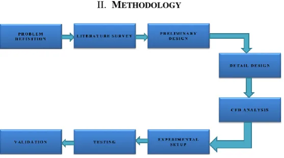
II. METHODOLOGY
Fig. 2.1: Analysis & Experimental procedure and the components
The above flow chart represents the step by step working procedure of this work. The focus of the proposed study to determine the flow characteristics at different conditions during operation and to achieve at an optimum result against the experimental and/or existing literature results. The rigorous work involves the modeling& analysis of the entire annular exhaust diffuser using CATIA, ANSYS FLUENT & ICEM-CFD.
In the present study symmetrical airfoil shaped struts are used as it as leading edge radius which supports for the swirl flow angle of attacks also it contributes for lower drag and thus increasing the efficiency of the exhaust diffuser. The annular diffuser is incorporated with airfoil struts with spokes wheel which diffuses and de-swirls the flow. Further the flow will go through the nozzle which further increases the velocity with producing more thrust than it was producing without diffuser.
The experimental setup is carried out in laboratory, the obtained results validated against to the numerical and/or existing literature results.
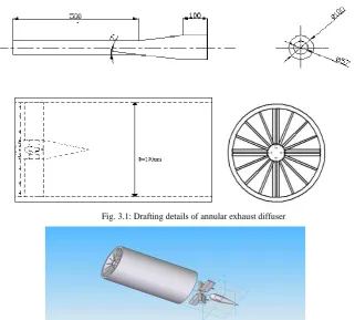
III. MODELLING OF ANNULAR EXHAUST DIFFUSER
Fig. 3.1: Drafting details of annular exhaust diffuser
Fig. 3.2: Exploded view of annular exhaust diffuser
3.1 Computational Domain Construction
The physical problem under consideration is the flow inside annular exhaust diffuserin a computational domain as shown in the Fig 3.3.
Fig. 3.3: Computational Domain for annular exhaust diffuser (iso view)
3.2 Meshing
Fig. 3.3: Computational domain for annular exhaust diffuser
3.3 Test Case
This is the test carried out for larger swirl number that is S>0.6. Since the area ratio is being 0.8. The diffuser in particular is tested for swirl number 0.8, which means both tangential and axial velocities are equal. Since the diffuser is subsonic the diffuser is tested for 100 m/s of tangential and axial velocities.
Since the mass flow rate is same and inlet and outlet radius are 80 mm and 100 mm respectively so the swirl number is reduced to,
𝑆 = 𝑚 × 𝑟 ∗ 𝑣𝜃
𝑚 × 𝑟 ∗ 𝑢
𝑆 =𝑟𝑖 × 𝑉𝜃
𝑟𝑜 × 𝑢
𝑆 = 80 × 100
100 × 100
𝑆 = 0.8
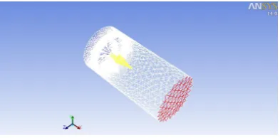
Therefore for given tangential and axial velocity of 100m/s and 80m/s the swirl number is 0.8, which is greater than 0.6, so we are dealing with higher swirl number.In this phase, the annular diffuser is incorporated with 4 airfoil struts and 2 spokes wheel at 2 different planes with 16 spokes at every plane of spoke wheel, aerofoil strut being NACA 0035 symmetrical airfoil profile and tested for higher swirl number.CFD analysis is carried out for the diffuser by setting up the boundary conditions at inlet, outlet and enclosure as shown below
Fig. 3.4: Assigning boundary conditions (Blue- inlet, Red-outlet & White- enclosure)
The above Fig.3.4 shows the boundary conditions, solution method and initializing the solution, calculation is initialized for 100 iterations. After the solution reached convergence the calculation will be done.
IV.RESULTS AND DISCUSSION
avoided the turbulence at a given velocity we can easily say that transition flow is avoided in other words postponed to higher velocity thus increasing the transition Reynolds number achieving.
Fig. 4.1: Showing converted flow from swirl to laminarFig. 4.2: Side view showing conversion of swirl flow to laminar
Fig. 4.3: Side view showing volume rendering of pressure
The above Fig 4.3 shows the volume rendering of pressure, it gives idea about the pressure recovery, that is the pressure lost during the conversion of the flow from swirl into laminar is regained at the conical diffuse part also which reduces the pressure gradient, as the pressure lost during the conversion is regained by some magnitude lower than at inlet allowing the flow to avoid surge.
V. EXPERIMENTAL SETUP
5.1 Fabrication Details:
The scaled annular diffuser model is built according to the dimensions as shown in Fig 3.1. The experimental set up consists of all the components like spokes, struts and diffuser section. In order to visualize the flow a transparent acrylic pipe is used in place of casing and an exhaust fan fitting to the diameter of the pipe is used to produce swirl flow inside the tube which simulates the turbine effect. In order to measure static pressure the pressure probes are placed at appropriate locations. In order to visualize the flow smoke flow visualization technique is employed such that an appropriate diameter hole is made near the inlet on the pipe so that smoke pipe exactly fit in. The exhaust fan is made to change its position along the length of the diffuser pipe in order to maintain required swirl. Since the fan is producing large swirl so it is placed at the inlet. A typical wind tunnel smoke generator is used to visualize the swirl flow and its transformation into laminar flow.
Fig. 5.1: Transparent acrylic pipe Fig. 5.2: Model Front view Fig. 5.3: Side view of experimental model
5.2 Testing
The test setupwith smoke generator is made to run in order to validate the theoretical result obtain from the ANSYS FLUENT. Initially the setup was tested with model replacing the nozzle section. Due to the blower limitations there was no sufficient mass flow of air to measure the static pressure before and after the spokes section also the smoke flow visualization was merely possible.
To overcome the difficulties the alternate method of running the fan with electric power was used. Although this method doesn’t provide sufficient velocity as same that of tested in ANSYS FLUENT but it provided proportional effect with sufficient mass flow rate for smoke flow visualization.
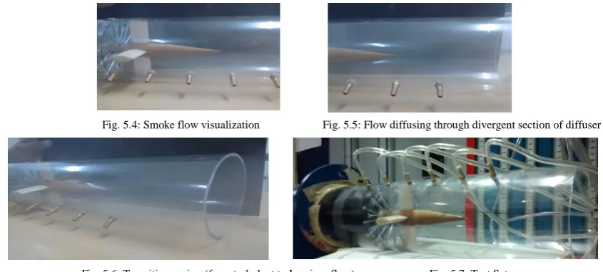
The smoke flow visualization is carried out in order to validate the process of conversion of swirl flow into laminar. This conversion of laminar flow also shows the flow being laminar will delay the transition Reynolds number. The following observations were recorded during the testing.
Fig. 5.4: Smoke flow visualization Fig. 5.5: Flow diffusing through divergent section of diffuser
Fig. 5.6: Transition region (from turbulent to Laminar flow) Fig. 5.7: Test Setup
The experimental observations are recorded and with observation data and experimental data to validate. Experimental data has clearly shown the flow being turned to nearly straight flow from swirl flow so is the ANSYS post processor results. This validates the first objective of turning the swirl flow into laminar flow.
VI.CONCLUSION
From the experimental analysis using both software and hardware it can be concluded that the turning the excessive swirl flow into laminar flow with the advantage of avoiding turbulent flow, increase the transitional Reynolds number. Smoke flow visualization of the experimental setup concludes that the flow being converted from swirl into laminar as predicted in Fluent. Conversion of swirl flow to laminar flow also concludes that flow remains laminar which was previously transiting to turbulent. This concludes the increase in transition Reynolds number.
Studying the volume rendering of pressure shows the pressure recovery. The pressure lost during the flow through the spokes is recovered at end of the divergent. There by concluding the decrease in pressure gradient.
SCOPE FOR THE FUTURE WORK
There are many ideal conditions assumed during the present project so there is always room for improvement and accurate result. Following implementations could be undertaken in future to simulate more actual and more accurate flow.
1. Parametric studies can be conducted for different spokes sizes and shapes, like elliptical spokes arrangement to study Deswirling effects.
2. Studies on Transitional Reynolds number and transition process can be conducted.
3. Experimental studies with more accurate instruments can be conducted to obtain accurate results. 4. Temperature study and vibration study can be conducted.
5. Effect on swirl flow on afterburner has a good potential in future.
Most of the research work on this field is carried with laminar flow. Therefore this field needs more necessary research swirl flow interaction in order to have more efficient jet engines.
REFERENCES
[1] VaddinChetan, D V Satish, Dr. Prakash S Kulkarni “Numerical Investigations of PGT10 Gas TurbineExhaust Diffuser Using Hexahedral Dominant Grid” International Journal of Engineering and Innovative Technology (IJEIT) Volume 3, Issue 1, July 2013
[2] R.Prakash, D.Christopher, K.Kumarrathinam “CFD Analaysis of Flow Through a Conical Exhaust Diffuser” IJRET: International Journal of Research in Engineering and Technology eISSN: 2319-1163 | pISSN: 2321-7308
[3] R.Keerthana, G.Jamuna Rani “Flow analysis of annular diffusers” R.Keerthana, G.jamuna rani: International Journal of Engineering Research and Applications (IJERA) ISSN: 2248-9622 www.ijera.comVol. 2, Issue 3, May-Jun 2012, pp.2348-2351.
[4] Christopher Barker, Chad Carrol, Cyrus Hanson, David Kaligamba, Adam Kauffman, Aron Romasanta,Aaron Settles, Vince Tizzone, Mathew Travis, Joshua Weed, Aaron Wilbur “Final Report for ASHRAE Senior Undergraduate Project Grant Program Swirling Pipe Flow Laboratory Students Involved in Project” Oral Roberts University, 7777 S Lewis Avenue, Tulsa, OK 74171.
[5] Sovran, G., Klomp, E.D, “Experimentally determined optimum geometries for rectilinear diffusers with rectangular, conical, or annular cross sections.” In: Sovran, Gino (Ed.), Fluid Mechanics of Internal Flow, Elsevier Publishing Company, New York, pp. 272-319.
[6] John D. Anderson. Jr: "Computational Fluid Dynamics", the basics with applications, McGraw-Hill International Editions. [7] PradipNiyogi, S.K.Chakrabarthy and M.K.Laha, "Introduction to Computational Fluid Dynamics”, Pearson Education.
[8] Angelina M Padilla, et al, "The Effect of Inlet Distortion on 3D Annular Diffusers", International Journal of Heat and Fluid Flow, Vol.34, pp.494-503.
BIOGRAPHY
Mr VENUGOPAL M M BE (Mech), MTech (Aero), (Ph.D)
Assistant Professor, Department of Aeronautical Engineering. Acharya Institute of Technology, Bangalore, Karnataka, INDIA.
Mr Venugopal M M, a well-known Asst. Professor and Researcher. He has completed his M.Tech from MVJCE, Bangalore.He has teaching experience in the area of mechanical and aeronautical engineering. He has published several research papers in national & international Journals and conferences.
Mr SOMASHEKAR VmDAE, BE (Mech), MTech (Aero), LMISTE
Assistant Professor, Department of Aeronautical Engineering, Acharya Institute of Technology, Bangalore, Karnataka, INDIA.
Mr Somashekar V, a well-known Asst. Professor and researcher. He has completed his M.Tech from MVJCE, Bangalore. He has a mixed experience of industry as well as teaching in the area of mechanical and aeronautical engineering. He has published several research papers in national & international Journals and conferences. He has authored several books.