LIU, DONGGANG. Security Mechanisms for Wireless Sensor Networks. (Under the direction of Assistant Professor Peng Ning).
Wireless sensor networks have received a lot of attention recently due to their wide applications in military and civilian operations. Example applications include target tracking, scientific exploration, and data acquisition in hazardous environments. Security becomes one of the main concerns when there are malicious attacks against the network. However, providing security services in such networks turns out to be a challenging task due to the resource constraints on sensor nodes and the node compromise attacks. These features and challenges motivate the research on security mechanisms for wireless sensor networks.
This dissertation includes three studies on security mechanisms for wireless sensor networks. The first study extends the capabilities of µTESLA, a broadcast authentication technique for wireless sensor networks, so that it can cover a long time period and support a large number of sensor nodes as well as potential senders in the network.
The second study addresses how to establish pairwise keys between sensor nodes in a wireless sensor network. A key pre-distribution framework based on bivariate polynomial pool is developed for this purpose. Two efficient instantiations of this framework are also provided: a random subset assignment scheme and a hypercube-based key pre-distribution scheme. To further improve the pairwise key establishment in static sensor networks, prior deployment knowledge, post deployment knowledge and group-based deployment knowledge are used to facilitate key pre-distribution.
by
Donggang Liu
A dissertation submitted to the Graduate Faculty of North Carolina State University
in partial satisfaction of the requirements for the Degree of
Doctor of Philosophy
Department of Computer Science
Raleigh
2005
Approved By:
Dr. Carla D. Savage Dr. Mladen A. Vouk.
Biography
Donggang Liu is a PhD student in the Department of Computer Science at North Carolina State University from 2001 to 2005. He received his M.S. degree from Institute of Computing Technology, Chinese Academy of Science, in 2001, and B.E. degree from the Department of Computer Science and Engineering, Beijing Institute of Technology, in 1998.
Acknowledgements
Pursuing and completing a PhD study in the area of Computer Science is a challenging mission. I would like to thank all those who have supported me during my PhD education. I would like to thank my adviser, Dr. Peng Ning. His guidance and wisdom show me the way of doing research in the area of Computer Science. I would like to thank my committee members, Dr. Douglas S. Reeves, Dr. Carla D. Savage, and Dr. Mladen A. Vouk, for their valuable feedback and comments on my research. I would like to thank Professor Sushil Jajodia who offered me an opportunity to visit George Mason University for two months, which gave me valuable experience on collaborative work. I would like to thank Dr. Annie I. Anton, Dr. Cliff Wang, Dr. Laurie Williams, Dr. Jun Xu and Dr. Ting Yu for their helpful feedback and comments in research meetings and discussions.
I would like to thank the National Science Foundation (NSF), Army Research Office (ARO) and NCSU Center for Advanced Computing & Communication (CACC) for their funding support. I would like to thank NDSS’03, CCS’03 and ICDCS’05 for their student travel support.
I would like to give my thanks to all my friends for their help in my PhD study (sorted by name): Hua Li, Pai Peng, Julia M. Star, Kun Sun, Pan Wang, Dingbang Xu, Yan Zhai, Qinghua Zhang, Sencun Zhu. I would like to thank Fay Ward for proofreading my thesis.
Contents
List of Figures viii
List of Tables xiii
1 Introduction 1
1.1 Motivation . . . 2
1.1.1 Broadcast Authentication . . . 4
1.1.2 Pairwise Key Establishment . . . 5
1.1.3 Security in Localization . . . 6
1.2 Summary of Contributions . . . 8
1.3 Organization of the Dissertation . . . 10
2 Background 12 2.1 Broadcast Authentication in Sensor Networks . . . 12
2.2 Key Pre-Distribution Techniques in Sensor Networks . . . 15
2.2.1 Polynomial-Based Key Pre-Distribution . . . 15
2.2.2 Probabilistic Key Pre-Distribution . . . 16
2.3 Other Related Work on Sensor Network Security . . . 18
2.4 Localization in Sensor Networks . . . 19
3 Extending µTESLA Broadcast Authentication Technique 22 3.1 Multi-Level µTESLA . . . 23
3.1.1 Scheme I: Predetermined Key Chain Commitment . . . 24
3.1.2 Scheme II: Naive Two-Level µTESLA . . . 25
3.1.3 Scheme III: Fault Tolerant Two-Level µTESLA . . . 28
3.1.4 Scheme IV: DOS-Tolerant Two-Level µTESLA . . . 31
3.1.5 Scheme V: DOS-Resistant Two-Level µTESLA . . . 39
3.1.6 Scheme VI: Multi-Level µTESLA . . . 42
3.1.7 Experimental Results . . . 52
3.2 Tree-Based µTESLA . . . 56
3.2.1 The Basic Approach . . . 57
3.2.3 Distributing Parameter Certificates . . . 63
3.2.4 Revoking µTESLA Instances . . . 64
3.2.5 Implementation and Evaluation . . . 68
3.3 Summary . . . 72
4 Polynomial Pool-Based Key Pre-Distribution 74 4.1 Polynomial Pool-Based Key Pre-Distribution . . . 76
4.1.1 Phase 1: Setup . . . 77
4.1.2 Phase 2: Direct Key Establishment . . . 77
4.1.3 Phase 3: Path Key Establishment . . . 79
4.2 Key Pre-Distribution Using Random Subset Assignment . . . 81
4.2.1 The Random Subset Assignment Scheme . . . 81
4.2.2 Performance . . . 82
4.2.3 Overheads . . . 83
4.2.4 Security Analysis . . . 84
4.2.5 Comparison with Previous Schemes . . . 86
4.3 Hypercube-based Key Pre-Distribution . . . 90
4.3.1 The Hypercube-Based Scheme . . . 91
4.3.2 Dynamic Key Path Discovery . . . 94
4.3.3 Performance . . . 97
4.3.4 Overhead . . . 97
4.3.5 Security Analysis . . . 99
4.3.6 Comparison with Previous Schemes . . . 104
4.4 Implementation and Evaluation . . . 106
4.4.1 Optimization of Polynomial Evaluation on Sensor Nodes . . . 107
4.4.2 Evaluation . . . 109
4.5 Summary . . . 111
5 Improving Key Pre-Distribution Using Deployment Knowledge 112 5.1 Improving Key Pre-Distribution with Prior Deployment Knowledge . . . 113
5.1.1 A Location-Aware Deployment Model . . . 113
5.1.2 Closest Pairwise Keys Scheme . . . 115
5.1.3 Closest Polynomials Pre-Distribution Scheme . . . 125
5.2 Improving Key Pre-Distribution with Post Deployment Knowledge . . . 136
5.2.1 Key Prioritization Using Post Deployment Knowledge . . . 137
5.2.2 Improving Random Subset Assignment Scheme with Deployment Lo-cations . . . 138
5.3 Improving Key Pre-Distribution with Group-Based Deployment . . . 146
5.3.1 Group-Based Deployment Model . . . 147
5.3.2 A General Framework . . . 148
5.3.3 Performance Analysis . . . 152
5.3.4 Security Analysis . . . 158
6 Secure Location Discovery 168
6.1 Pitfalls of Current Localization Schemes in Presence of Malicious Attacks . 169
6.2 Attack-Resistant Location Estimation . . . 171
6.2.1 Assumptions . . . 171
6.2.2 Attack-Resistant Minimum Mean Square Estimation (MMSE) . . . 172
6.2.3 Voting-Based Location Estimation . . . 178
6.2.4 Security Analysis . . . 184
6.2.5 Simulation Evaluation . . . 185
6.2.6 Implementation and Field Experiments . . . 191
6.3 A Detector for Malicious Beacon Nodes . . . 194
6.3.1 Detecting Malicious Beacon Signals . . . 195
6.3.2 Filtering Replayed Beacon Signals . . . 197
6.3.3 Revoking Malicious Beacon Nodes . . . 204
6.3.4 Simulation Evaluation . . . 210
6.4 Summary . . . 213
7 Conclusions and Future Work 215 7.1 Contributions . . . 215
7.2 Future Work . . . 217
List of Figures
1.1 Attacks against location discovery schemes . . . 7 2.1 µTESLA protocol. . . 13 2.2 Probability of sharing at least one key for different combinations of key pool
size and the number of keys at sensor nodes. . . 17 2.3 Fraction of compromise links between non-compromised sensor nodes for the
basic probabilistic scheme and the q-composite scheme when p = 0.33 and s′ = 200. . . 18 2.4 An example of localization method. Nodes A,B and C are beacon nodes,
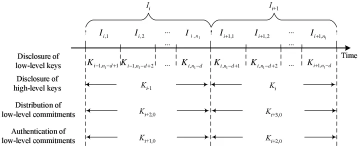
and node O is a non-beacon node. . . 20 3.1 The two levels of key chains in Scheme II. Each keyKi is used for the
high-level time intervalIi, and each keyKi,j is used for the low-level time interval
Ii,j. F0 and F1 are different pseudo random functions. Each commitment
Ki,0 is distributed during the time interval Ii−2. . . 28
3.2 Key disclosure schedule in Scheme II . . . 28 3.3 The two levels of key chains in Scheme III. It differs from Figure 3.1 in that
each Ki,n1 is derived from Ki+1 using an additional pseudo random function
F01. . . 29
3.4 State transition diagram for Scheme IV . . . 36 3.5 Bandwidth required forCDM messages to ensure 90% of low-level key chain
commitments are authenticated before the key chains are used. . . 38 3.6 Bandwidth for CDM messages v.s. number of key chain levels. Assume the
number ofCDM buffers in each key chain level is m= 40. . . 45 3.7 The performance with different buffer allocation schemes for total memory
512 and 1024 bytes to buffer data and CDM messages. Assume 95% of CDM packets are forged and 50% of packets are lost when transmitted over the channel. . . 54 3.8 Experimental results under different channel loss rate and percentage of
3.10 Example of a parameter distribution tree for long-lived schemes . . . 62 3.11 Example of fragmentation . . . 64 3.12 Authentication rate under 0.2 loss rate and 200 forged parameter distribution
packet per minute. . . 69 3.13 Channel loss rate: 0.2; # forged commitment distribution: 200 per minute;
distribution rate: 95%. . . 70 3.14 Average failure recovery delay. Assume 20 parameter distribution packet per
minute. . . 71 4.1 Probabilities about pairwise key establishment . . . 84 4.2 Performance of the random subset assignment scheme under attacks. RS
refers to the random subset assignment scheme. Assume each node has avail-able storage for 200 keys andp= 0.33. . . 87 4.3 The probability of re-establishing a pairwise key using path discovery.
As-sume each node has available storage equivalent to 200 keys, and contacts 30 neighbor nodes d= 30. AssumeN = 20,000 . . . 87 4.4 The relationship between the probability of establishing a common key and
the maximum supported network size in order to be resilient against node compromise. . . 90 4.5 Hypercube-based key pre-distribution whenn= 2 . . . 92 4.6 Performance of the hypercube-based scheme . . . 98 4.7 Security performance of the hypercube-based scheme. Assume each sensor
has available storage equivalent to 50 keys, N = 20,000, m = √n
N, and t=⌊50n −1⌋. . . 101 4.8 Maximum supported network size for different number of dimensions.
As-sume each sensor has available storage equivalent to 50 keys. . . 102 4.9 Probability of re-establishing a pairwise key between non-compromised nodes
v.s. the fraction of compromised nodes. Assume that each sensor node has available storage equivalent to 50 keys andN = 20,000. . . 104 4.10 Performance of the grid-based key pre-distribution scheme under attacks.
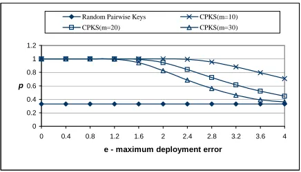
Assume each sensor node has available storage equivalent to 200 keys. . . . 105 4.11 Comparison with RC5 and SkipJack. . . 110 5.1 Probability of establishing direct keys between two neighbor nodes given
different values of e and γ. CPKS denotes the closest pairwise keys pre-distribution scheme. . . 119 5.2 Probability of establishing direct keys in random pairwise keys scheme and
the closest pairwise keys scheme for different m and e given c = 200 and N = 600. . . 121 5.3 Fraction of compromised pairwise keys between non-compromised sensor
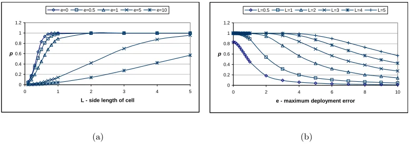
nodes v.s. number of compromised sensor nodes. RS denotes the random subset assignment scheme . . . 122 5.4 Partition of a target field . . . 127 5.5 Probability of establishing direct keys between two neighbor nodes given
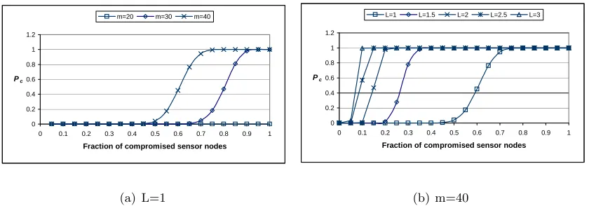
5.6 Fraction of compromised direct keys between non-compromised sensor nodes v.s. fraction of compromised sensor nodes. Assume each node has available
storage equivalent to 200 cryptographic keys. . . 132
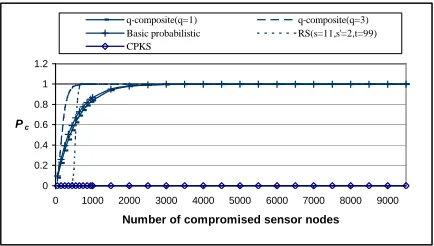
5.7 Fraction of compromised direct keys between non-compromised sensor nodes v.s. number of compromised sensor nodes. Assume each node has available storage equivalent to 200 cryptographic keys. Assumep= 0.33 andm= 40. CPPS denotes the closest polynomials pre-distribution random scheme. . . 134
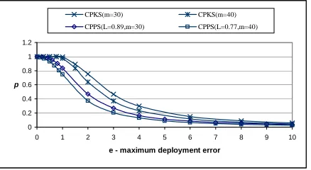
5.8 Probability of establishing pairwise key directly between two neighbor nodes given differenteandm. The length of cell side in CPPS is configured so that it is perfectly resistant to the node captures. Assume each node has available storage equivalent to 200 cryptographic keys. . . 134
5.9 Shared circles of neighbor sensor nodes . . . 140
5.10 Probability of sharing a direct key between neighbor sensor nodes. . . 142
5.11 Security performance of the improved scheme in Situation 1. . . 143
5.12 Security performance of the improved scheme in Situation 2. . . 145
5.13 Deployment Distribution . . . 147
5.14 Example of group construction . . . 150
5.15 Probability of having a direct key between two neighbor nodes. . . 155
5.16 Probability of having a direct key between two neighbor sensor nodes. Mem-ory usage is measured by counting the number of keys stored on each node. 156 5.17 Probability of having a direct key between two neighbor sensor nodes. Mem-ory usage is measured by counting the number of keys stored on each node. 156 5.18 Probability of having a direct key between two neighbor sensor nodes. Mem-ory usage is measured by counting the number of polynomial coefficients stored on each node. . . 157
5.19 Probability of having indirect keys between sensor nodes in different deploy-ment groups. Memory usage is measured by counting the number of keys or polynomial coefficients stored on each node. . . 159
5.20 Probability of a direct key between two non-compromised nodes being com-promised. Assume the probability of having a direct key between two neigh-bor nodes is 0.3. . . 161
5.21 Probability of a direct key between two non-compromised nodes being com-promised. Assume the probability of having a direct key between two neigh-bor nodes is 0.3. . . 162
5.22 pgci−in(c) for the group-based EG scheme and the probability of an indi-rect key being compromised for the basic probabilistic scheme. Assume the probability of having a direct key between two neighbor nodes is 0.3. . . 163
5.23 pgci−in(c) for the group-based PB scheme and the probability of an indirect key being compromised for the random subset assignment scheme. Assume the probability of having a direct key between two neighbor nodes is 0.3. . . 164
5.25 pgci−cr(c) for the group-based PB scheme and the probability of an indirect
key being compromised for the random subset assignment scheme. Assume
the probability of having a direct key between two neighbor nodes is 0.3. . . 167
6.1 Location estimation error of a MMSE-based method in presence of malicious attacks . . . 170
6.2 The effect of malicious attacks on the mean square errorς2 . . . 173
6.3 Cumulative distribution function for the mean square error of location esti-mation on benign location references. Let c= ς0 ǫ. . . 177
6.4 The voting-based location estimation . . . 179
6.5 Determine whether a ring overlaps with a cell . . . 180
6.6 Cumulative probability distribution of location estimation error for different partition configurations. Assume the location error created by a malicious beacon node is 20m, and the measurement error isǫ= 4m. . . 182
6.7 Performance of attack-resistant MMSE (with 9 benign location references) . 185 6.8 Average number of removed location references v.s. the value of thresholdτ. Assume there are 9 benign location references and each malicious location reference introduces 40m location error. . . 187
6.9 Performance for different M (e: error introduced by a malicious location reference) . . . 188
6.10 Computational cost for differentM (e: error introduced by a malicious loca-tion reference) . . . 189
6.11 Performance of the voting-based scheme (M = 100 andS = 0) . . . 189
6.12 Attack-resistant MMSE scheme v.s. the voting-based scheme . . . 190
6.13 Performance under different distance measurement errors (assume that the location error introduced by each malicious location references is 10m) . . 190
6.14 Average execution time on MICA2 motes (ǫ= 4m, τ = 0.8ǫ, M = 100 and S = 0) . . . 191
6.15 Target area of field experiment. . . 192
6.16 Performance of the attack-resistant schemes in the field experiment (M = 100 and S = 0 for the voting-based scheme; τ = 0.8ǫ = 3.2 feet for attack-resistant MMSE) . . . 194
6.17 Detect malicious beacon signals . . . 196
6.18 Round trip time . . . 199
6.19 Cumulative distribution of round trip time . . . 200
6.20 Relationship between Pr and P. . . 204
6.21 Detection rate v.s. probability of non-beacon nodes being affected. Nc = 100. 206 6.22 Detection rate. m= 8 and τ = 2. . . 207
6.23 Average number of affected non-beacon nodes after all detected malicious beacon nodes are revoked from the network. m= 8 and Nc = 100. . . 208
6.24 Average number of affected non-beacon nodes when P is chosen in such a way that P′ is maximized. . . . 209
6.26 Deployment of beacon nodes in a sensing field. . . 212 6.27 Detection rate v.s. P. Assume τ′ = 2 andτ = 2. . . 212 6.28 Average number of requesting non-beacon nodes accepting the malicious
List of Tables
1.1 Characteristic of MICA2 and MICA2dot motes. . . 2 4.1 Communication and computational overheads for direct key establishment in
different schemes. sk is the key pool size in the basic probabilistic scheme
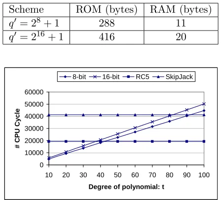
and the q-composite scheme. s′ = t+1C . The last row will be discussed in Section 4.3. . . 89 4.2 Code sizes for our optimized polynomial evaluation schemes. . . 110 4.3 The code size for random subset assignment and grid-based scheme. The
storage for the polynomial coefficients and the list of compromised nodes are not included in the calculation of code size. . . 110 5.1 Notations . . . 117 5.2 Notations . . . 153 6.1 Code size for different schemes (assume a maximum of 12 location references;
Chapter 1
Introduction
A sensor network typically consists of a large number of tiny sensor nodes and possibly a few powerful control nodes (also called base stations). A sensor node is usually composed of one or a few sensing components, which are able to sense conditions (e.g. temperature, humidity, pressure) from its immediate surroundings, and a processing and communication component, which is able to carry out simple computation on raw data and communicate with its neighbor nodes in short distances. The control nodes may further process the data collected from sensor nodes, disseminate control commands to sensor nodes, and connect the network to a traditional wired network. Sensor nodes are usually densely deployed on a large scale and communicate with each other through wireless links [1]. There is usually no infrastructure for a sensor network. These features imply a variety of applications of sensor networks in military and civilian operations, such as target tracking, battlefield surveillance, and wildlife habitat monitoring.
Table 1.1: Characteristic of MICA2 and MICA2dot motes.
MICA2 MICA2dot
Processor 8-bit 7.7MHz ATmega128 8-bit 4MHz ATmega128
RAM 4K bytes 4K bytes
ROM 128K bytes 128K bytes
EEPROM 512K bytes 512K bytes
Data Rate 38.4K baud 38.4k baud
Default Packet Size 29 bytes 29 bytes (under TinyOS[25])
Power Supply 2 AA batteries 1 coin cell battery
Obviously, the design of such networks requires wireless networking techniques, especially wireless ad hoc networking techniques. However, most traditional wireless net-working protocols and algorithms are not suitable for sensor networks. The main challenge of designing a sensor network comes from the resource constraints on sensor nodes. Table 1.1 shows some basic characteristics of typical MICA2 and MICA2dot motes [13], which are widely used in current generation of sensor networks. The protocols and algorithms in sensor networks are usually application-specific in order to achieve high performance and save valuable resources at sensor nodes.
The wide applications of sensor networks and the challenges in designing such networks have attracted many researchers to develop protocols and algorithms for sensor networks (e.g., [62, 25, 20, 54, 30, 53, 1]). This research focuses on the security mechanisms of sensor networks in hostile environments, where there are malicious attacks against the network.
1.1
Motivation
• Resource constraints: As shown in Table 1.1, sensor nodes are usually resource con-strained, especially energy constrained. Every operation reduces the lifetime of a sensor node. This makes it impractical to perform expensive operations such as pub-lic key cryptography (e.g. RSA [67]) on sensor nodes. For example, a pubpub-lic key is usually 1024 bits (128 bytes) or 2048 bits (256 bytes) long, while a sensor network may only support small size packets as shown in Table 1.1. Though the size of mes-sages can be increased, it is generally not practical to accommodate a long message, since wireless communication is one of the most expensive operations on sensor nodes. In addition, public key operation usually involves many expensive computations (e.g. large integer modular exponentiations).
• Node compromise: Different from traditional wireless networks, where each individual node may be physically protected, the large scale of wireless sensor networks makes it impractical to protect or monitor each individual sensor node physically. An at-tacker may capture or compromise one or a number of sensor nodes without being noticed. If sensor nodes are compromised, the attacker learns all the secrets stored on them and may launch a variety of malicious actions against the network through these compromised nodes. For example, the compromised nodes may discard all im-portant messages in order to hide some critical events from being noticed, or report observations that are significantly different from those observed by non-compromised nodes in order to mislead any decision made based on these data. The result will be even worse if the nodes that provide some critical functions (e.g. data aggregation) are compromised.
Though using tamper-resistance hardwares may help to protect security sensitive data on sensor nodes, this solution generally increases the cost of an individual sensor node dramatically. An alternative way is to develop security protocols that areresilientto node compromise attacks in the sense that even if one or a number of sensor nodes are compromised, the sensor network can still function correctly.
(e.g., topology). Thus, we have to use resource-constrained sensor nodes to deal with very powerful attacks.
In this dissertation, I study two fundamental security services in wireless sensor networks: broadcast authentication and pairwise key establishment. In addition, I also investigate how to protect a critical service, location discovery, in wireless sensor networks.
1.1.1 Broadcast Authentication
Broadcast authentication is an essential security service in wireless sensor net-works. Because of the large number of sensor nodes and the broadcast nature of wireless communication, it is usually desirable for base stations to broadcast commands and data to sensor nodes. The authenticity of such commands and data is critical for the normal operation of sensor networks. If convinced to accept forged or modified commands or data, sensor nodes may perform unnecessary or incorrect operations and cannot fulfill the intended purposes of the network. Thus, in hostile environments (e.g., battle field, anti-terrorists op-erations), it is necessary to enable sensor nodes to authenticate broadcast messages received from base stations.
Providing broadcast authentication in distributed sensor networks is a non-trivial task. On the one hand, public key based digital signatures (e.g., RSA [67]), which are typi-cally used for broadcast authentication in traditional networks, are too expensive to be used in sensor networks, due to the intensive computation involved in signature verification and the resource constraints on sensor nodes. On the other hand, secret key based mechanisms (e.g., HMAC [36]) cannot be directly applied to broadcast authentication, since otherwise a compromised receiver can easily forge any message from the sender.
The original TESLA uses broadcast to distribute the initial parameters required for broadcast authentication. The authenticity of these parameters are guaranteed by a digital signature generated by the sender. However, due to the low bandwidth of a sensor network and the low computational resources at each sensor node,µTESLA cannot distribute these initial parameters using public key cryptography. Instead, the base station has to unicast the initial parameters to the sensor nodes individually. Such a method certainly cannot scale up to very large sensor networks, which may have thousands of nodes.
Techniques to address this problem are provided in Chapter 3.
1.1.2 Pairwise Key Establishment
Pairwise key establishment is another important fundamental security service. It enables sensor nodes to communicate securely with each other using cryptographic tech-niques. The main problem here is to establish a secure key shared between two commu-nicating sensor nodes. However, due to the resource constraints on sensor nodes, it is not feasible for them to use traditional pairwise key establishment techniques such as public key cryptography and key distribution center (KDC).
Instead of the above two techniques, sensor nodes may establish keys between each other through key pre-distribution, where keying materials are pre-distributed to sensor nodes before deployment. As two extreme cases, one may setup a global key among the network so that two sensor nodes can establish a key based on this key, or one may assign each sensor node a unique random key with each of the other nodes. However, the former is vulnerable to the compromise of a single node, and the latter introduces huge storage overhead at sensor nodes.
security over the basic probabilistic key pre-distribution scheme.
However, the pairwise key establishment problem is still not fully solved. For the basic probabilistic and theq-composite key pre-distribution schemes, as the number of compromised nodes increases, the fraction of affected pairwise keys increases quickly. As a result, a small number of compromised nodes may disclose a large fraction of pairwise keys. Though the random pairwise keys scheme does not suffer from the above security problem, given a memory constraint, the network size is strictly limited by the desired probability that two sensor nodes share a pairwise key, the memory available for keys on sensor nodes, and the number of neighbor nodes that a sensor node can communicate with.
Techniques to address this problem are provided Chapter 4 and Chapter 5.
1.1.3 Security in Localization
Sensors’ locations play a critical role in many sensor network applications. Not only do applications such as environment monitoring and target tracking require sensors’ location information to fulfill their tasks, but several fundamental techniques developed for wireless sensor networks also require sensor nodes’ locations. For example, in geographical routing protocols (e.g., GPSR [34] and GEAR [79]), sensor nodes make routing decisions at least partially based on their own and their neighbors’ locations. As another example, in some data-centric storage applications such as GHT [65, 72], storage and retrieval of sensor data highly depend on sensors’ locations. Indeed, many sensor network applications will not work without sensors’ location information.
beacon node nb
(x, y)
attacking node na
n
(x’, y’)
I’m nb; my location is (x, y)
(a) Masquerade beacon nodes
malicious beacon
node nb
(x, y)
n
I’m nb; my location
is (x’, y’)
(b) Compromise beacon nodes
!"#$%&"&' (
(c) Replay beacon signals
Figure 1.1: Attacks against location discovery schemes
location when it has a sufficient number of location references from different beacon nodes. A typical approach is to consider the location references as constraints that a sensor node’s location must satisfy, and estimate it by finding a mathematical solution that satisfies these constraints with minimum estimation error.
Despite the recent advances, location discovery for wireless sensor networks in hos-tile environments, where there may be malicious attacks, has been mostly overlooked. The only exception is a location verification scheme [69] that allows a node to verify the location claimed by another node using special hardware. As a matter of fact, all of the existing location discovery protocols become vulnerable in the presence of malicious attacks. As illustrated in Figure 1.1, an attacker may provide incorrect location reference by pretending to be valid beacon nodes (Figure 1.1(a)), compromising beacon nodes (Figure 1.1(b)), or replaying the beacon packets that he/she intercepted in different locations (Figure 1.1(c)). In either of the above cases, non-beacon nodes will determine their locations incorrectly. The location verification technique proposed in [69] can verify the relative distance between neighbor nodes; however, it cannot guarantee correct location discovery if a malicious bea-con node lies about its location.
additional mechanisms to improve the security of location discovery in sensor networks. Some solutions to address this problem are provided in Chapter 6.
1.2
Summary of Contributions
The contributions of this dissertation are summarized below:
• Multi-levelµTESLA: The first contribution is a multi-levelµTESLA technique, which is used to extend the capabilities of the originalµTESLA. The main idea is to prede-termineandbroadcast the initial parameters required by µTESLA instead of unicast-based message transmission. Specifically, the proposed technique constructs a multi-level key chain scheme, in which the higher-multi-level key chains are used to authenticate the commitments of lower-level ones. To further improve the survivability of the scheme against message loss and Denial of Service (DOS) attacks, redundant message transmissions and random selection strategies are used to deal with the messages that distribute key chain commitments. The resulting scheme removes the requirement of unicast-based initial communication between base station and sensor nodes while keeping the desirable properties ofµTESLA (e.g., tolerance of message loss, resistance to replay attacks). The experimental results demonstrate that the proposed scheme can tolerate high channel loss rate and is resistant to known DOS attacks to a certain degree.
• Tree-based µTESLA: The second contribution is a tree-based µTESLA technique, which is developed to support a potentially large number of broadcast senders us-ing µTESLA instances as building blocks. The basic idea is to take advantage of Merkle hash tree [49] to authenticate the initial parameters of µTESLA instances. The proposed techniques are immune to the DOS attacks. In addition, a revocation tree based scheme and a proactive distribution based scheme are proposed to revoke the broadcast authentication capability from compromised senders. The analysis and experiment show that the proposed techniques are efficient and practical and can achieve better performance than the previous approaches.
for this purpose by using the polynomial-based key pre-distribution protocol in [5] and the probabilistic key distribution scheme in [19, 11]. We also show two efficient instantiations of this framework: a random subset assignment key pre-distribution scheme and a hypercube-based key pre-distribution scheme. The analysis shows that these schemes have a number of nice properties, including high probability to estab-lish pairwise keys, tolerance of node captures, and low storage, communication, and computation overhead. To further reduce the computation at sensor nodes, we also presents an optimization technique for polynomial evaluation, which is used to com-pute pairwise keys. we also report the implementation and the performance of these schemes on MICA2 motes running TinyOS [25], an operating system for networked sensors. The results indicate that the proposed techniques can be applied efficiently in resource-constrained sensor networks.
• Attack-resistant location estimation: The fifth contribution is on how to protect lo-cation discovery service in sensor networks, where sensor nodes accept a number of malicious beacon signals in addition to the benign ones and tries to estimate accurate locations based on the beacon signals. We presents two methods to survive malicious attacks against location discovery in sensor networks. The first method filters out malicious beacon signals on the basis of the “consistency” among multiple beacon sig-nals, while the second method tolerates malicious beacon signals by adopting a voting scheme. Both methods can survive malicious attacks even if the attacks bypass tradi-tional cryptographic protections such as authentication, as long as the benign beacon signals constitute the majority of the “consistent” beacon signals. We also present the implementation of the proposed techniques on MICA2 motes running TinyOS as well as the evaluation through both simulation and field experiments. The experimental results demonstrate that the proposed methods are not only effective but also practi-cal in surviving malicious attacks against location discovery in the current generation of sensor networks.
• Detecting Malicious Beacon Nodes: The sixth contribution is on how to detect and remove compromised beacon nodes that supply misleading location information to the regular sensors, aiming at providing secure location discovery services in wire-less sensor networks. These techniques start with a simple but effective method to detect malicious beacon signals. To identify malicious beacon nodes and avoid false detection, we also present several techniques to detect replayed beacon signals. We then propose a method to reason about the suspiciousness of each beacon node at the base station based on the detection results collected from beacon nodes and revoke malicious beacon nodes accordingly. The analysis and experimental results show that these techniques are practical and effective in detecting malicious beacon nodes.
1.3
Organization of the Dissertation
Chapter 2
Background
2.1
Broadcast Authentication in Sensor Networks
)*+, ) * )*-,
. . .
.
/01 2
3 5 4 6 7 8
9:;<=>;? @ ABCBD
9:;<=>;? @ ABD
9:;<=>;? @ AECBD FABC G
*
G *-,
Figure 2.1: µTESLA protocol.
µTESLA protocol introduces asymmetry by delaying the disclosure of symmetric keys [62]. A sender broadcasts a message with a Message Authentication Code (MAC) generated with a secret keyK, which will be disclosed after a certain period of time. When a receiver receives this message, if it can ensure that the packet was sent before the key was disclosed, the receiver can buffer this packet and authenticate it when it receives the corresponding disclosed key. This requires loose time synchronization between the sender and the receivers. To continuously authenticate the broadcast packets, µTESLA divides the time period for broadcasting into multiple time intervals and assigns different keys to different time intervals, as shown in Figure 2.1. All packets broadcasted in a particular time interval are authenticated with the same key assigned to that time interval. For example, packets 1, 2 are authenticated with Ki−1, packet 3 is authenticated with Ki, and packets
4,5,6 are authenticated with Ki+1.
To authenticate the broadcast messages, a receiver first authenticates the disclosed keys. µTESLA uses a one-way key chain for this purpose. As shown in Figure 2.1, the sender selects a random valueKnas the last key in the key chain and repeatedly performs a pseudo
random functionF to compute all the other keys: Ki =F(Ki+1),0≤i≤n−1, where the
secret keyKiis assigned to theithtime interval. With the pseudo random functionF, given
Kj in the key chain, anybody can compute all the previous keysKi,0≤i≤j, but nobody
can compute any of the later keysKi, j+ 1≤i≤n. Thus, with the knowledge of the initial
any key in the key chain by merely performing pseudo random function operations. When a broadcast message is available in ith time interval, the sender generates MAC for this
message with a key derived fromKi and then broadcasts this message along with its MAC
and discloses the key Ki−d assigned to the time interval Ii−d, wheredis the disclosure lag
of the authentication keys. The sender prefers a long delay in order to make sure that all or most of the receivers can receive its broadcast messages. But, for the receiver, a long delay could result in high storage overhead to buffer the messages.
Each key in the key chain will be disclosed after certain delay. As a result, an attacker can forge a broadcast packet by using the disclosed key. µTESLA uses a security condition to prevent a receiver from accepting any broadcast packet authenticated with a disclosed key. When a receiver receives an incoming broadcast packet at time intervalIi, it
checks the security condition ⌊(Tc+ ∆−T0)/Tint⌋< Ii+d, whereTc is the local time when
the packet is received, T0 is the start time of the time interval 0,Tintis the duration of each
time interval, and ∆ is the maximum clock difference between the sender and itself. If the security condition is satisfied, i.e., the sender has not disclosed the keyKi yet, the receiver
accepts this packet. Otherwise, the receiver simply drops it. When the receiver receives the disclosed key Ki, it can authenticate it with a previously received key Kj by checking
whether Kj =Fi−j(Ki), and then authenticate the buffered packets that were sent during
time intervalIi.
µTESLA is an extension to TESLA [60]. The only difference between TESLA and µTESLA is in their key chain commitment distribution schemes. TESLA uses asymmetric cryptography to bootstrap new receivers, which is impractical for current sensor networks due to its high computation and storage overhead. µTESLA depends on symmetric cryp-tography with the master key shared between the sender and each receiver to bootstrap the new receivers individually. In this scheme, the receiver first sends a request to the sender, and then the sender replies a packet containing the current time Tc (for time
synchroniza-tion), a key Ki of the one-way key chain used in a past interval i, the start time Ti of
intervali, the durationTint of each time interval and the disclosure lag d.
Perrig et al. proposed to use an earlier key chain to distribute the commitments of the next key chain [59]. Multiple early TESLA packets are used to tolerate packet losses. However, since reliable distribution of later commitment cannot be fully guaranteed, if all the packets used to distribute commitments are lost (e.g., due to temporary network partition), a receiver will not be able to recover the commitment of the later key chain. As a result, the sender and the receivers will have to repeat the costly bootstrap process.
2.2
Key Pre-Distribution Techniques in Sensor Networks
This section reviews two types of techniques to perform key pre-distribution in the context of resource constrained sensor networks: the polynomial-based key pre-distribution [5] and the probabilistic key pre-distribution [19, 11, 63].
2.2.1 Polynomial-Based Key Pre-Distribution
The original key distribution protocol in [5] was developed for group key pre-distribution. Since the goal is to establish pairwise keys, for simplicity, we only discuss the special case of pairwise key establishment in the context of sensor networks.
To pre-distribute pairwise keys, the (key) setup server randomly generates a bi-variatet-degree polynomialf(x, y) =Pti,j=0aijxiyj over a finite fieldFq, whereqis a prime
number that is large enough to accommodate a cryptographic key, such that it has the prop-erty of f(x, y) = f(y, x). (In the following, we assume that all the bivariate polynomials have this property without explicit statement.) It is assumed that each sensor node has a unique ID. For each nodei, the setup server computes apolynomial shareoff(x, y), that is, f(i, y). This polynomial share is pre-distributed to nodei. Thus, for any two sensor nodes iand j, nodeican compute the keyf(i, j) by evaluatingf(i, y) at pointj. And nodej can compute the same key f(j, i) =f(i, j) by evaluating f(j, y) at pointi. As a result, nodesi and j can establish a common keyf(i, j).
The security proof in [5] ensures that this scheme is unconditionally secure and t-collusion resistant. That is, the coalition of no more than t compromised sensor nodes knows nothing about the pairwise key between any two non-compromised nodes.
It is theoretically possible to use the general group key distribution protocol in [5] in sensor networks. However, the storage cost for a polynomial share is exponential in terms of the group size, making it prohibitive in sensor networks. This dissertation focuses on the problem of pairwise key establishment.
2.2.2 Probabilistic Key Pre-Distribution
A probabilistic key pre-distribution technique was proposed to bootstrap initial trust between sensor nodes in [19]. The main idea is to have each node randomly pick a set of keys from a key pool before deployment so that any two sensor nodes can share a common key with certain probability. Specifically, a setup server, which is assumed to be trusted, generates a large pool of random keys, where each key has a unique key ID. Each sensor node then gets assigned a random subset of keys as well as their IDs from this pool before the deployment of this sensor node.
In order to establish a common key directly between two sensor nodes after deploy-ment, the nodes only need to identify a common key ID they share. This can be achieved by exchanging the list of key IDs they have. The probability of sharing at least one common key can be easily derived for a given key pool size s and the number of keys s′ at sensor nodes using the following equation [19].
p= 1−
s′−1
Y
i=0
s−s′−i s−i
For example, if the key pool size is 100,000 and each sensor node randomly gets assigned 200 keys, the probability of sharing at least one common key is about 0.33. Figure 2.2 shows the probability of sharing at least one key for different combinations of key pool size and the number of keys assigned to each sensor node.
0 0.2 0.4 0.6 0.8 1
0 50 100 150 200
s'
P
roba
bi
li
ty
of
s
ha
ri
ng
a
ke
y
s=1000 s=5000 s=10,000 s=100,000
Figure 2.2: Probability of sharing at least one key for different combinations of key pool size and the number of keys at sensor nodes.
Chan et al. extended the basic probabilistic key pre-distribution scheme and pro-posed theq-composite key pre-distribution scheme [11]. This approach requires two sensor nodes to setup a pairwise key only when they share at least q common keys. This idea im-proves the security of the basic probabilistic scheme [19] when there are a small number of compromised sensor nodes. Pietro et al. proposed a seed-based key deployment strategy to simplify the key discovery procedure and a cooperative protocol to enhance its performance [63].
The advantage of the above key pre-distribution schemes is that they require a small amount of memory at sensor nodes but guarantee a high probability of sharing a common key between two sensor nodes. The main disadvantage is that a small number of compromised sensor nodes discloses a large fraction of secrets in the network, which is shown in Figure 2.3. The reason is that the same key may be shared by more than two sensor nodes.
Chan et al. also developed a random pairwise keys scheme to defeat node capture attacks [11]. In this scheme, the setup server randomly selects a pair of sensor nodes and distributes a unique random key between them. The benefit is that none of the keys shared directly between non-compromised sensor nodes will be disclosed no matter how many sensor nodes are compromised. The disadvantage is that the maximum supported network size is limited by the storage overhead and the desired probability of sharing a key between sensor nodes directly.
0 0.1 0.2 0.3 0.4 0.5
0 20 40 60 80 100 120 140
Number of compromised nodes
F
ra
ct
ion
of
c
om
pr
om
is
ed
li
nks basic probabilistic scheme q-composite (q=1)
q-composite (q=2) q-composite (q=3)
Figure 2.3: Fraction of compromise links between non-compromised sensor nodes for the basic probabilistic scheme and the q-composite scheme whenp= 0.33 and s′ = 200.
our scheme provides a more general framework, which makes it possible to discover novel key pre-distribution schemes. The idea of using prior deployment knowledge was independently discovered in [16] and our work [42] to improve the key pre-distribution schemes.
2.3
Other Related Work on Sensor Network Security
In addition to the above two security services, there are a lot of other related work on sensor network security. Stajano and Anderson discussed bootstrapping trust between devices through location-limited channels such as physical contact [74]. Carman, Kruus, and Matt studied the performance of a number of key management approaches in sensor network on different hardware platforms [10]. Wong and Chan proposed reducing the computational overhead for key exchange in a low power computing device with the help of a more power server [77].
Basagni et al. presented a key management scheme to secure the communication by periodically updating the symmetric keys shared by all sensor nodes [3]. However, this scheme assumes a tamper-resistant device to protect the key, which is not always available in sensor networks. Zhu et al. proposed a protocol suite named LEAP (Localized Encryption and Authentication Protocol) to help establish individual keys between sensors and a base station, pairwise keys between sensors, cluster keys within a local area, and a group key shared by all nodes [80].
se-curity for in-networking processing [14]. Zhu et al. proposed an interleaved hop-by-hop authentication to defeat malicious data injection in sensor networks [81]. The problem of secure data aggregation in the presence of compromised nodes is studied in [26] and [64].
Wood and Stankovic identified a number of DOS attacks in sensor networks [78]. Karlof and Wagner pointed out security goals for routing in sensor networks and analyzed the vulnerabilities as well as the countermeasures for a number of existing routing protocols [33]. Sastry, Shankar and Wagner proposed a location verification technique based on the round trip time (RTT) [69] to detect false location claims. Hu and Evans proposed using directional antennae to detect wormhole attacks in wireless Ad Hoc networks [27]. Newsome et al. studied the Sybil attack in sensor networks where a node illegitimately claims multiple identities and developed techniques to defend against this attack [52].
2.4
Localization in Sensor Networks
Existing localization schemes either employ range-based methods, which use the exact measurements obtained in stage one, or range-freemethods, which only need the ex-istences of beacon signals in stage one. Typical techniques to obtain the measurements be-tween two nodes include Received Signal Strength Indicator (RSSI), Time of Arrive (ToA), Time Difference of Arrive (TDoA), and Angle of Arrive (AoA).
The basic idea of localization in sensor networks can be illustrated through a simple example. As shown in Figure 2.4, non-beacon node O wants to estimate its location. In the first phase, NodeO measures the distances d1,d2, and d3 to beacon nodeA,B and C
respectively, based on the received beacon signals. In the second phase, node O lists the following equations according to the measured distances and the locations of beacon nodes.
f1 =d1−
p
(x−x1)2+ (y−y1)2
f2 =d2−
p
(x−x2)2+ (y−y2)2
f3 =d3−
p
(x−x3)2+ (y−y3)2
A (x1, y1)
B (x2, y2) C (x
3, y3)
O (x, y) d1
d2 d3
Figure 2.4: An example of localization method. NodesA,B and C are beacon nodes, and node O is a non-beacon node.
f1 =d1−
p
(x−x1)2+ (y−y1)2
f2 =d2−
p
(x−x2)2+ (y−y2)2
..
. ...
fm =dm− p
(x−xm)2+ (y−ym)2
With these equations, we can use the technique in [70] to estimate the location of sensor nodes.
The above example shows the basic idea of a range-based localization scheme. Range-based localization schemes in sensor networks include those in [70, 71, 55, 51, 15]. Savvides et al. developed AHLoS localization protocol based on Time Difference of Arrive [70]. Extension of this work can be found in [71]. Doherty et al. presented a localization scheme based on connectivity-induced constraints and the relative angle between neighbors [15]. Angle of Arrive is also used to develop localization schemes in [55] and [51].
Chapter 3
Extending
µ
TESLA Broadcast
Authentication Technique
In this chapter, we first present amulti-level µTESLA to extend the capabilities ofµTESLA. The basic idea is topredetermineandbroadcast the initial parameters required by µTESLA instead of using unicast-based message transmission. In the simplest form, this extension distributes the µTESLA parameters during the initialization of the sensor nodes (e.g., along with the master key shared between each sensor and the base station). To provide more flexibility, especially to prolong the lifetime ofµTESLA without requiring a very long key chain, we introduce a multi-level key chain scheme in which the higher-level key chains are used to authenticate the commitments of lower-higher-level ones. To further improve the survivability of the scheme against message loss and Denial of Service (DOS) attacks, we use redundant message transmissions and random selection strategies to deal with the messages that distribute key chain commitments. The resulting scheme removes the requirement of unicast-based initial communication between base station and sensor nodes while keeping the nice properties of µTESLA (e.g., tolerance of message loss, resistance to replay attacks). The experimental results demonstrate that this scheme can tolerate high channel loss rate and is resistant to known DOS attacks to a certain degree.
senders over a long period of time by using Merkle hash tree [49]. This method has the following advantages over the multi-levelµTESLA schemes: (1) It allows broadcast authen-tication in large sensor networks with a large number of senders, while multi-level µTESLA schemes (as well as the original µTESLA protocol) is not scalable in terms of the number of senders. (2) It is not subject to the DOS attacks against the distribution ofµTESLA pa-rameters. In contrast, multi-level µTESLA schemes either consume substantial bandwidth or require significant resources at senders in order to defeat such DOS attacks. To deal with the limited packet payload size in sensor networks, we adopt the idea in [31] and develop a simple method to distribute large messages required for authenticating µTESLA param-eters over multiple packets. A nice property of this method is that it allows immediate authentication of the segments of such messages and thus is immune to DOS attacks.
We also develop two complementary techniques to revoke broadcast authentica-tion capability from compromised senders: a revocaauthentica-tion tree-based scheme and a proactive distribution scheme. The former constructs a Merkle hash tree to revoke compromised senders, while the latter proactively controls the distribution of broadcast authentication capability of each sender to allow the revocation of compromised senders.
3.1
Multi-Level
µ
TESLA
The major barrier of usingµTESLA in large sensor networks lies in its difficulty with distributing the key chain commitments to a large number of sensor nodes. In other words, the method for bootstrapping new receivers in µTESLA does not scale to a large group of new receivers, though it is okay to bootstrap one or a few. The essential reason for this difficulty is the mismatch between the unicast-based distribution of key chain commit-ments and the authentication ofbroadcast messages. That is, the technique is developed for broadcast authentication, but it relies on unicast-based technique to distribute the initial parameters.
very resourceful in terms of computational power. The final scheme, a multi-level µTESLA scheme, then has two variations based on schemes IV and V, respectively.
We assume each broadcast message is from the base station to the sensor nodes. Broadcast messages from a sensor node to the sensor network can be handled as suggested in [62]. That is, the sensor node unicasts the message to the base station, which then broad-casts the message to the other sensor nodes. The messages transmitted in a sensor network may reach the destination directly, or may have to be forwarded by some intermediate nodes; however, we do not distinguish between them in our schemes.
For the sake of presentation, we denote the key chain with commitment K0 as
hK0i throughout this chapter.
3.1.1 Scheme I: Predetermined Key Chain Commitment
A simple solution to bypass the unicast-based distribution of key chain commit-ments is to predetermine the commitcommit-ments, the starting times, and other parameters of key chains to the sensor nodes during the initialization of the sensor nodes, possibly along with the master keys shared between the sensor nodes and the base station. (Unlike the master keys, whose confidentiality and integrity are both important, only the integrity of the key chain commitments needs to be ensured.) As a result, all the sensor nodes have the key chain commitments and other necessary parameters once they are initialized, and they are ready to useµTESLA as long as the starting time is passed.
This simple scheme can greatly reduce the overhead involved in distribution of key chain commitments in µTESLA since unicast-based message transmission is no longer required. However, this simple solution also introduces several problems.
in order to authenticate a later disclosed key. Continuing from the previous example, if the time between two consecutive messages received in a sensor is one hour, the sensor has to perform 60×60×10 = 36,000 pseudo random operations to verify the disclosed key, which may be prohibitive in resource-constrained sensors. If a long interval is used, there will be a long delay before the authentication of a message after it is received, and it requires a larger buffer at each sensor node. Though the extensions to TESLA [61] can remove the delay in authenticating the data payload and the buffer requirement at the sensor nodes, the messages will have to be buffered longer at the base station.
Second, it is difficult to predict the starting time of a key chain when the sensor nodes are initialized. If the starting time is set too early, the sensor nodes will have to compute a large number of pseudo random functions in order to authenticate the first broadcast message. As shown in the previous example, one hour delay will introduce a huge number of pseudo number operations. In addition, the key chain must be fairly long so that it does not run out before the sensor network’s lifetime ends. If the starting time is set too late, messages broadcasted before it cannot be authenticated viaµTESLA.
These problems make this simple scheme not a practical one. In the following, we propose several additional techniques so that we not only avoid the problems of unicast-based distribution of key chain commitment but also those of this simple scheme.
3.1.2 Scheme II: Naive Two-Level µTESLA
The essential problem of Scheme I lies in the fact that it is impossible to use both a short key chain and short time intervals to cover a long period of time. This conflict can be mitigated by using multiple levels of key chains. In the following several subsections, we first investigate the special case of two-level key chains to enhance security and robustness, and then extend the results to multi-level key chains in Section 3.1.6.
The lifetime of a sensor network is divided into n0 (long) intervals of duration
∆0, denoted as I1, I2, ..., and In0. The high-level key chain has n0+ 1 elements K0,K1,
..., Kn0, which are generated by randomly picking Kn0 and computing Ki =F0(Ki+1) for
i= 0,1, ..., n0 −1, where F0 is a pseudo random function. The key Ki is associated with
each time interval Ii. We denote the starting time of Ii as Ti. Thus, the starting time of
the high-level key chain isT1.
Since the duration of the high-level time intervals is usually very long compared with the network delay and clock discrepancies, we choose to disclose a high-level key Ki
used forIi in the following time intervalIi+1. Thus, we use the following security condition
to check whether the base station has disclosed the key Ki when a sensor node receives a
message authenticated with Ki at time t: t+δM ax < Ti+1, where δM ax is the maximum
clock discrepancy between the base station and the sensor node.
Each time interval Ii is further divided into n1 (short) intervals of duration ∆1,
denoted as Ii,1, Ii,2, ..., Ii,n1. If needed, the base station generates a low-level key chain
for each time interval Ii by randomly picking Ki,n1 and computing Ki,j = F1(Ki,j+1) for
j = 0,1, ..., n1 −1, where F1 is a pseudo random function. The key Ki,j is intended for
authenticating messages broadcasted during the time intervalIi,j. The starting time of the
key chain hKi,0i is predetermined as Ti. The disclosure lag for the low-level key chains
can be determined in the same way as µTESLA and TESLA [60, 62]. For simplicity, we assume all the low-level key chains use the same disclosure lag d. Further assume that messages broadcasted during Ii,j are indexed as (i, j). Thus, the security condition for a
message authenticated with Ki,j and received at time t is i′ < (i−1)∗n1 +j+d, where
i′=⌊t−T1+δM ax
∆1 ⌋+ 1, andδM ax is the maximum clock discrepancy between the base station
and the sensor node.
When sensor nodes are initialized, their clocks are synchronized with the base station. In addition, the starting timeT1, the commitment K0 of the high-level key chain,
the duration ∆0 of each high-level time interval, the duration ∆1 of each low-level time
interval, the disclosure lagdfor the low-level key chains, and the maximum clock discrepancy δM ax between the base station and the sensor nodes throughout the lifetime of the sensor
network are distributed to the sensors.
In order for the sensors to use a low-level key chainhKi,0iduring the time interval
Ii, they must authenticate the commitment Ki,0 beforeTi. To achieve this goal, the base
interval Ii. (In the rest of this chapter, we use commitment distribution message and its
abbreviation CDM interchangeably.) This message consists of the commitment Ki+2,0 of
the low-level key chain hKi+2,0i and the key Ki−1 in the high-level key chain. Specifically,
the base station constructs the CDMi message as follows:
CDMi =i|Ki+2,0|M ACK′
i(i|Ki+2,0)|Ki−1, where “|” denotes message concatenation,
and K′
i is derived from Ki with a pseudo random function other than F0 and F1.
Thus, to use a low-level key chain hKi,0i duringIi, the base station needs to generate the
key chain during Ii−2 and distributeKi,0 inCDMi−2.
Since the high-level authentication keyKi is disclosed inCDMi+1 during the time
interval Ii+1, each sensor needs to store CDMi until it receives CDMi+1. Each sensor
also stores a key Kj, which is initially K0. After receiving Ki−1 in CDMi, the sensor
authenticates it by verifying thatF1i−1−j(Ki−1) =Kj. Then the sensor replaces the current
Kj withKi−1.
Suppose a sensor has receivedCDMi−2. Upon receivingCDMi−1duringIi−1, the
sensor can authenticate CDMi−2 withKi−2 disclosed in CDMi−1, and thus verifyKi,0. As
a result, the sensor can authenticate broadcast messages sent by the base station using the µTESLA key chain hKi,0i during the high-level time intervalIi.
This scheme usesµTESLA in two different levels. The high-level key chain relies on the initialization phase of the sensor nodes to distribute the key chain commitment, and it only has a single key chain throughout the lifetime of the sensor network. The low-level key chains depend on the high-level key chain to distribute and authenticate the commitments. Figure 3.1 illustrates the two-level key chains, and Figure 3.2 displays the key disclosure schedule for the keys in these key chains.
The two-level key chains scheme mitigates the problem encountered in Scheme I. On the one hand, by having long time intervals, the high-level key chain can cover a long period of time without having a very long key chain. On the other hand, the low-level key chain has short time intervals so that authentication of broadcast messages does not have to be delayed too much.
HIJK HI HILK MMM
HIJKNK HIJKNO HINK HINO HIPKNK HIPKNO MMM MMM
QR QR QR QR
QK QK QK QK QK QK QK QK QK MMM
MMM MMM
STUV H
INR
HIPKNR HIPWNR QK
QK QK
QK HIPXNR
HIPWNK
1 , 1 n i K− 1 , 2 n i
K− Ki,n1 Ki+1 n,1
Figure 3.1: The two levels of key chains in Scheme II. Each keyKi is used for the high-level
time interval Ii, and each keyKi,j is used for the low-level time interval Ii,j. F0 andF1 are
different pseudo random functions. Each commitment Ki,0 is distributed during the time
intervalIi−2.
YYY YYY YYY
YYY Z[ Z[\]
^[\_`a
^[\b`a YYY
YYY cdef g
dhijkh lm
fkn jk
op jf
q fjrf
s h g
dhijkh lm f kn t du t p jf q fjrf
s h g dhv m dw l
vdkxkn jk
op jf
q
fjikeedvefxvh
^[y]
^ [ ^[\]`a ^[\_`a z
l v
t
fxvdi{vdkxkn jk
op jf
q
fjikeedvefxvh
1 , 1 1− +
− n d i
K 1, 2
1− +
− n d i
K Kin−d
1
, Ki,n1−d+1 Ki,n1−d+2 Ki+1,n1−d 1 , n i I 1 , i
I Ii,2 Ii+1,1 Ii+1,2 Ii+1 n,1
Figure 3.2: Key disclosure schedule in Scheme II
in this scheme. Thus, similar toµTESLA and TESLA, a sensor can detect forged messages by verifying the MAC with the corresponding authentication key once the sensor receives it. In addition, replay attacks can be easily defeated if a sequence number is included in each message.
3.1.3 Scheme III: Fault Tolerant Two-Level µTESLA
|}~ |} |} |}~ |}~ |} |} |} |} |} |} |} |} |} 1 , 1 n i K− 1 , 2 n i
K− Ki,n1 Ki+1 n,1
Figure 3.3: The two levels of key chains in Scheme III. It differs from Figure 3.1 in that each Ki,n1 is derived fromKi+1 using an additional pseudo random functionF01.
chained together. Thus, losses of a key disclosure messages for later keys in a low-level key chain cannot be recovered even if the sensor can receive keys in some later low-level key chains. For example, consider the last key Ki,n1 that is used to authenticate the packet in
the key chain of time intervalIi. If theCDM message that carries the disclosure ofKi,n1 is
lost, the sensor then has no way to authenticate this packet. As a result, a sensor may not be able to authenticate a stored message even if it receives some key disclosure messages later. In contrast, with µTESLA a receiver can authenticate a stored message as long as it receives a later key. Second, if CDMi−2 does not reach a sensor, the sensor will not be
able to use the key chain hKi,0ifor authentication during the entire time intervalIi, which
is usually pretty long (to make the high-level key chain short).
To address the first problem, we propose to further connect the low-level key chains to the high-level one. Specifically, instead of choosing each Ki,n1 randomly, we derive each
Ki,n1 from a high-level key Ki+1 (which is to be used in the next high-level time interval)
through another pseudo random function F01. That is,Ki,n1 = F01(Ki+1). As a result, a
sensor can recover any authentication key Ki,j as long as it receives aCDM message that
discloses Ki′ withi′ >=i+ 1, even if it does not receive any later low-level key Ki,j′ with j′>=j. Thus, the first problem can be resolved. Figure 3.3 illustrates this idea.
The second problem does not have an ultimate solution; if the base station cannot reach a sensor at all during a time interval Ii, CDMi will not be delivered to the sensor.
One possible solution to mitigate the second problem is to include each key chain commitment in multiple CDM messages. For example, we may include each key chain commitment Ki,0 inlconsecutive CDM messages, CDMi−2, . . .,CDMi−(l+1). As a result,
CDMi includes the key chain commitments Ki+2,0, ..., Ki+1+l,0. A sensor can recover and
authenticate Ki,0 if it receives either any two of the abovel CDM messages, or one of the
l CDM messages andCDMi−1. However, this also increases the size of CDM messages as
well as the CDM buffer on sensor nodes. Moreover, the larger a packet is, the more likely it will be lost in wireless communication. Considering the fact that packets in distributed sensor networks usually have limited size (e.g., the payload of each packet in TinyOS [25] is at most 29 bytes), we decide not to go with this solution.
Instead, we propose to have the base station periodically broadcast the CDM message during each time interval. Assuming that the frequency of this broadcast is F, each CDM message is therefore broadcasted F ×∆0 times. To simplify the analysis, we
assume the probability that a sensor cannot receive a broadcast of a CDM message is pf.
Thus, the probability that a sensor cannot receive any copy of theCDM message is reduced to pF×∆0
f .
Note that even if a sensor cannot receive anyCDM message during a time interval Ii, it still has the opportunity to authenticate broadcast messages in time intervals later
than Ii+1. Not having the CDM message in time interval Ii only prevents a sensor from
authenticating broadcast messages duringIi+1. As long as the sensor gets aCDM message,
it can derive all the low-level keys in the previous time intervals.
By periodically broadcasting CDM messages, Scheme III introduces more over-head than Scheme II. Consider the overover-head on the base station, the sensors, and the com-munication channel respectively. Compared with Scheme II, this scheme does not change the computation ofCDM messages in the base station but increases the overhead to trans-mitCDM messages byF ×∆0 times. Base stations in a sensor network are usually much
more powerful than the sensor nodes. Thus, the increased overhead on base stations may not be a big problem as long as F×∆0 is reasonable.
measures.
This approach increases the overhead in the communication channel by F ×∆0
times since theCDM message for each time interval is repeated F×∆0 times. Assume the
probability that a sensor cannot receive a CDM message is pf = 1/2 and F ×∆0 = 10.
Under our simplified assumption, the probability that the sensor cannot receive any of the 10 CDM messages ispF×∆0
f <0.1%. Further assume that ∆0 is 1 minutes, which is quite
short as the interval length for the high-level key chain. Thus, there is one CDM message per 6 seconds. Assume the bandwidth is 10 kbps and each CDM packet is 36 bytes = 288 bits, which includes the 29 byteCDM message and the 7 byte packet header as in our experiments (Section 3.1.7). Then the relative communication overhead is 10240288×6 = 0.47%. This is certainly optimistic since we assume perfect channel utilization. However, it still shows that Scheme III introduces very reasonable communication overhead in typical sensor networks.
The security of Scheme III is similar to that of Scheme II. The only difference is that each low-level key chain in Scheme III is derived from a high-level key with a pseudo random function F01. Each high-level key is disclosed at least one high-level time interval
after the corresponding low-level key chain is used. Thus, as long as the pseudo random function is secure (i.e., it is computationally infeasible to distinguish the output of the pseudo random function from a true random number), Scheme III is equivalent to Scheme II, which does not have F01 connecting the two levels of key chains.
One limitation of Scheme III is that if a sensor misses all copies ofCDMi during
the time interval Ii, it cannot authenticate any data packets received during Ii+2 before
it receives an authentic Kj, j > i+ 2. (Note that the sensor does not have to receive an
authenticCDM message. As long as the sensor can authenticate a high-level key Kj with
j > i+ 2, it can derive the low-level keys through the pseudo random functions F0, F01,
and F1.) Since the earliest high-level key Kj that satisfies j > i+ 2 is Ki+3, and Ki+3 is
disclosed during Ii+4, the sensor has to buffer the data packets received during Ii+2 for at
least the duration of one high-level time interval.
3.1.4 Scheme IV: DOS-Tolerant Two-Level µTESLA