SIMULATION OF THE NUCLEAR FUEL ASSEMBLY DROP TEST WITH
LS-DYNA
P.Petkevich1, V.Abramov1, V.Yuremenko1, V.Piminov1, V.Makarov1, A.Afanasiev1
1Experimental and Design Organization "GIDROPRESS", Podolsk, RUSSIA
E-mail of corresponding author: [email protected]
ABSTRACT
Transportation of the nuclear fuel containing objects is especially sensitive to accidental drops, as any event, affecting the fuel spacial arrangement, alters also neutron multiplication factor and can result in uncontrolled chain reaction. The latter is particularly important for nuclear fuel being immersed in water. Apart from that, fall can result in a mechanical damage of the fuel rods, which can cause environmental pollution by radionuclides.
Final and intermediate fuel configurations during the accident depend on the impact velocity and the angle between falling object and the surface. Experiments cannot cover all the possible variants of drops, as it would result in their unacceptable prices. Therefore elaboration of the approaches to numerically simulate such kind of accidents is an essential step in the nuclear fuel transportation safety analysis and is the principal goal of the present research.
Series of drop tests with fuel assemblies (FA) models of different complexity have been performed and numerically simulated with LS-Dyna software in order to proof the reliability of such kind of analysis. The paper contains description of the drop test experimental facility, some experimental results and their numerical simulation. It has been found that the finite element model of the FA and the material properties used for the simulation provide reliable predictions of the FA materials deformation and failure in case of accidental drops onto a rigid surface.
INTRODUCTION
Transporting of nuclear fuel is potentially dangerous as any accident, affecting geometry or arrangement of the nuclear fuel, affects also neutron multiplication factor. Therefore nuclear safety during transportation has to be provided in any situation which is a Russian nuclear authorities requirement. To analyze neutronics of damaged nuclear fuel one has to be able to properly predict fuel deformations during and after the accident. LS-Dyna software [1, 2] is being currently used at EDO "Gidropress" for these purposes. However reliable analysis is hardly possible without thorough verification of the code for certain analysis types. Series of drop tests have been performed in order to proof the reliability of FA accidental drops numerical simulation. Numerical simulation of the experiments has shown a very good agreement between the results, which means that deformations of FA in accidental situations can be analyzed without expensive and complicated experiments.
PECULIARITIES OF THE FA NUMERICAL SIMULATION
Fig. 1. FA geometry and examples of accidents
Therefore each fuel rod and guide tube makes 39 contact pairs with spacer cells. Total amount of contact pairs is 1,3104. There are about 350 fuel pellets in a fuel rod. Each pellet contacts with cladding and neighboring
pellets which results in approximately 700 contact pairs per fuel rod. Thus, minimal amount of contact pairs to be considered per FA in any situation is 700312 + 1,3104 = 2,3105. Apart from that, results are greatly affected by
material properties deviations. Realistic simulation of desired dynamic processes cannot be realized using so called guaranteed (worst possible) material properties as it would not be conservative.
Hence development of a full-scale FA model has to be based on thorough investigations of the FA individual parts behaviour. It can be done by making experiments with relatively simple models which represent a single process without its interference with the other ones. Moreover reliable dynamic material properties have to be established
To do this a series of experiments was conducted. Four models were developed for experimental investigations: two relatively simple models; a shortened model of a real FA, with two spacers and a weight on the top to simulate mass of missing fuel pellets and a real fuel assembly including lead imitators of fuel pellets. The latter is not discussed in this paper. Description of other models and the experimental facility are given in the following sections.
EXPERIMENTAL SETUP
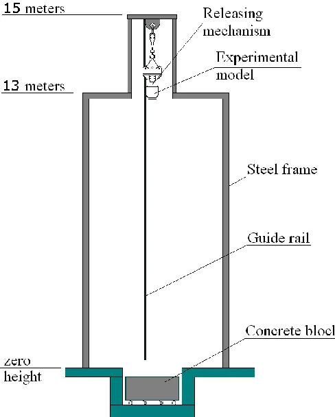
The target is made of a 30 mm thick steel plate casted in a concrete block of 18 tons weight. The block is put on springs to suppress its interaction with a bed of surrounding building.
Fig. 2. Schematics of the experimental facility
DESCRIPTION OF THE EXPERIMENTAL MODELS AND MEASUREMENTS PROCEDURE
The target is made of a 30 mm thick steel plate casted in a concrete block of 18 tons weight. The block is put on springs to suppress its interaction with a basement of surrounding building.
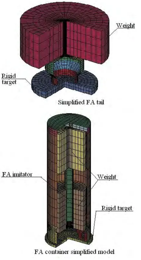
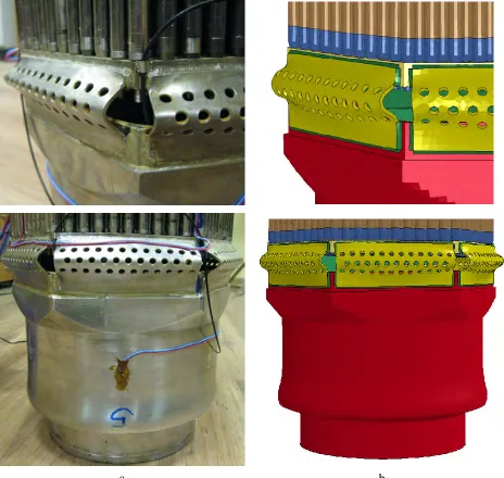
Usage of small and simple experimental models allows their multiple production and more detailed investigation. First of all increased number of experiments provide better statistics for each of the problems. Moreover subsequent experiments can be corrected (drop height, weight mass etc.) using the previous results. This is particularly important as numerical simulation of dynamic processes during investigated impact loading can be problematic. Finite-elements models used for numerical simulation of the drop tests are shown in Fig. 3.
The first model is a simplified FA tail and is used and investigate large plastic deformations (or damage) under high speed impact loading. These data are necessary for the verification of FE models and approaches to simulate such kind of interactions.
The second model used to simulate a drop of the nuclear fuel transportation container loaded with a FA. This is used to verify approaches to numerical simulation of accidental drops which can occur during fuel transportation (within a container) with LS-Dyna software. The principal outcomes of the experiment are the plastic deformations and damages of the FA and container stainless steel models as well as the data concerning fuel and container accelerations during the impact with a rigid target.
One of the experiment goals is to verify a finite-elements model developed with a reasonable minimum of simplifications. The major simplification is usage of shell elements to simulate fuel rods and spacer cells. A special attention was paid to the interaction of the edges with a perforated lower plate as the experiments have shown that their interpenetration and thus material damage takes place. The drop height was 2 meters.
Apart from the model itself Fig. 3 shows where strain gauges are placed: cylindrical part of a FA tail, fuel rods and gauges for measurements of transversal and longitudal strains of the edges welded to a tail (cannot be seen).
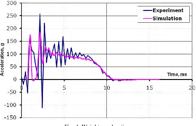
Weight deceleration after impact is one of the principal integral experimentally measured parameters of the drop test. It determines dynamics of the model's kinetic energy dissipation via plastic deformations of its components. Reliable prediction of deceleration is impossible without knowing real material properties and without proper description of the whole model. Deceleration of the weights was measured by accelerometers attached to them.
EXPERIMENTAL AND NUMERICAL SIMULATION RESULTS
Investigations of the simple models were conducted for the code verification purposes and for material properties establishment. All of the simulated results have shown a very good coincidence with the experimental data. The discussion of the large scale model experimental results and their comparison with the numerical simulation is given below.
Acceleration of the weight is shown in Fig. 4. A good agreement is obtained. Curve provided by the analysis is more smooth, as it's rather integral then a point characteristic. Otherwise moments of peak accelerations and the process duration are very well predicted by the analysis. The first acceleration maximum at 1.02 ms is a result of the edges and bottom grid interpenetration. At 2.17 ms tail starts to deform plastically which causes a second peak and slows the weight down to zero velocity.
Fig. 4. Weight acceleration
Support edge was equipped with a strain gauge. Fig. 5 shows measured deformations and results of numerical simulation for the elements highlighted in Fig. 5a. good agreement is obtained both for the strain time history and for residual strain.
a
b
Fig. 5. Time history of the lower edge strain
agreement is obtained for the deformations time history. The discrepancies can be explained be the imperfectness of the experimental model, slight differences in material properties, discretization of the FE model or by difference between measuring technique and analysis postprocessing.
Fig. 6. Time history of the tail's axial deformation
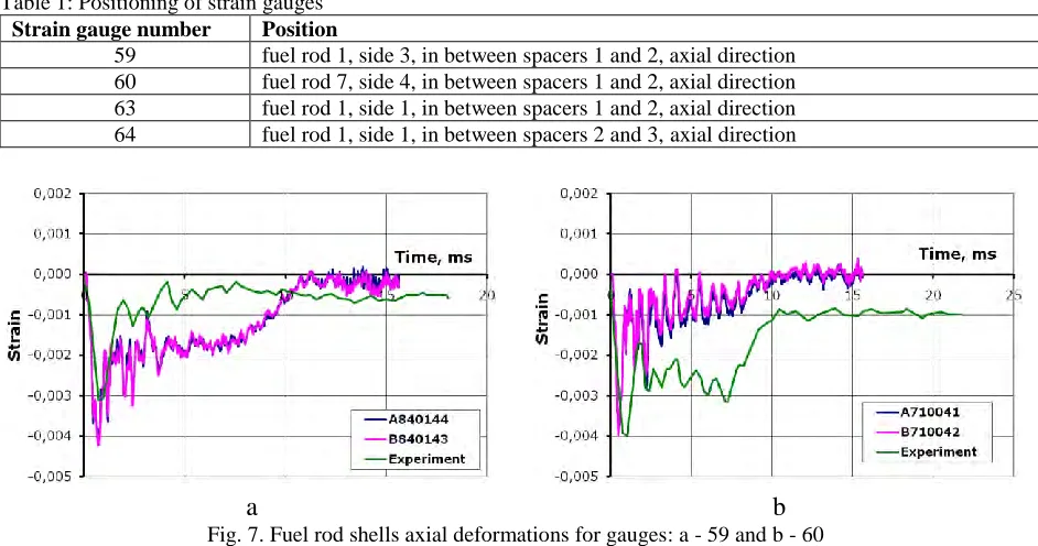
Deformations of the fuel rods cladding were measured by strain gauges placed on the corner rods in between the spacers. Numbering and position of gauges is given in Table 1 and in Fig. 7. Numbering of rods and sides is done clockwise (when being viewed from above) starting from the fixation pin. Comparison of the solution with the experimental date is shown in Fig. 7 and Fig. 8. In general good agreement is obtained. Peak strains at 1 ms are very well predicted. difference in residual stresses can arise from either insufficient bottom grid FE refinement or by using shell elements to model the fuel rods.
Table 1: Positioning of strain gauges
Strain gauge number Position
59 fuel rod 1, side 3, in between spacers 1 and 2, axial direction 60 fuel rod 7, side 4, in between spacers 1 and 2, axial direction 63 fuel rod 1, side 1, in between spacers 1 and 2, axial direction 64 fuel rod 1, side 1, in between spacers 2 and 3, axial direction
a
b
Fig. 7. Fuel rod shells axial deformations for gauges: a - 59 and b - 60
a
b
Fig. 8. Fuel rod shells axial deformations for gauges: a - 63 and b - 64
a
b
CONCLUSION
The present research was devoted to the application of LS-Dyna software for analysis related to the nuclear safety during nuclear fuel transportation accidents. The principal problem is to define deformed states of the fuel assembly during and after the accident. Series of experiments were conducted and numerically simulated. It has been shown that reliable solution can be obtained for a large scale model of a real FA. This means that newly developed nuclear fuel assemblies can be numerically investigated without conducting expensive and complicated experiments.
REFERENCES