20th International Conference on Structural Mechanics in Reactor Technology (SMiRT 20) Espoo, Finland, August 9-14, 2009 SMiRT 20-Division 4, Paper 3166
Structural Integrity Evaluation of Shielding Blocks for HANARO’s Cold
Neutron Guide
Jeong-Soo Ryu
a, Yeong-Garp, Cho
aand Kang-Soo Kim
aa
Korea Atomic Energy Research Institute, 150, Dukjin-dong, Yuseong-gu, Daejeon 305-353, Korea, e-mail: [email protected]
Keywords: shielding blocks, HANARO, cold neutron guide, structural integrity, seismic analysis
1
ABSTRACT
HANARO (Hi-flux Advanced Neutron Application Reactor) is a multi-purpose research reactor with a thermal power of 30MW. KAERI has been developing a HANARO’s cold neutron source (CNS) system. Cold neutron guide system consists of neutron guides, in-pile plug, primary shutter and shielding blocks. The shielding blocks are placed surrounding the primary shutter and cold neutron guides between the reactor pool wall and the CNS guide bunker in reactor hall. The shielding blocks are designed to protect the environment of radiation emanating from the primary shutter and the neutron guides. And these must be designed with a sufficient strength not to collapse when a SSE (Safe Shutdown Earthquake) occurs. To evaluate the structural integrity for the shielding blocks, the seismic model for them was made. The modal analysis for 3 model types according to the shielding block configuration and the seismic analysis were performed. 3D finite element models are made in order to calculate the maximum displacement for the shielding block. The seismic analysis for the shielding blocks was performed by using the response spectrum analysis method and the SAP 2000 code. The analysis results show that the maximum stress and displacement are within the code limits. Finally the detailed design for each structural element by using the data obtained from the seismic analysis for the shielding blocks was performed.
2
INTRODUCTION
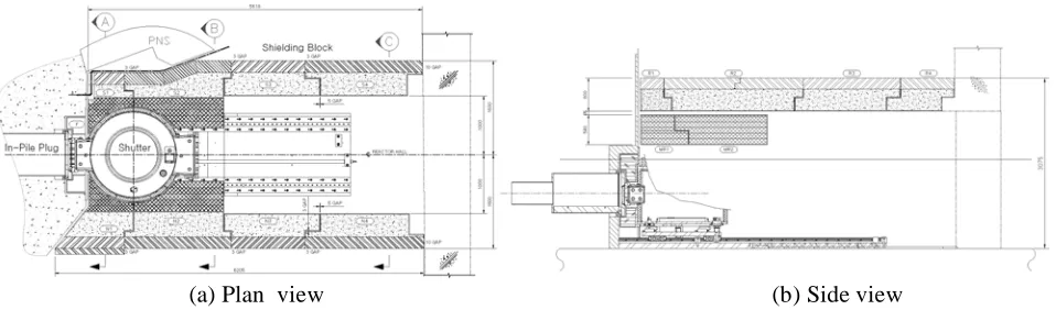
HANARO(Hi-flux Advanced Neutron Application Reactor) is a multi-purpose research reactor with a thermal power of 30MW. KAERI has been developing HANARO’s cold neutron source (CNS) system since 2003. These shielding blocks are designed to do the biological shielding of neutrons and gamma from the CN port, the primary shutter and the neutron guides. These consist of block type walls and roofs that can be necessarily assembled or disassembled. A total of 15 blocks as shown in Fig. 1 are placed between the outer wall of reactor pool and the CNS guide bunker in reactor hall. Design criteria for them are classified as non-nuclear safety (NNS), seismic category II, and quality class T.
(a) Plan view (b) Side view
Figure 1. Configuration of shielding blocks
concrete (3.5 g/cc) and polyethylene with 5% boron in a casemate. The shielding blocks must shield effectively the radiation emitted from facilities related to neutron guide and satisfy the requirements of the movable type facilities in the case of the necessity. The shielding blocks are classified as seismic category II because of the radiation shielding, the structural integrity of the reactor pool wall and the protection of internal facilities surrounded by the shielding blocks. Thus, in order to ensure the structural safety the shielding blocks and its related structures must be designed with a sufficient strength not to collapse when a SSE (Safe Shutdown Earthquake) occurs. The regulatory requirements and standards applied to the shielding blocks are presented in the references, ACI and ASCE.
(a) Section A (b) Section B (c) Section C
Figure 2.
Cross section shape of shielding blocks
3 STRUCTURAL INTEGRITY EVALUATION
3.1 Structural characteristics of shielding blocks.
The configurations of the shielding blocks surrounding HANARO Cold Neutron Guide are shown in Fig. 1. These are composed of the 3 types (section A, B and C) according to the cross section and shown in Fig. 2. Each shielding block is a steel casemate (steel housing), which are filled with the heavy concrete (3.5 g/cc) and polyethylene with 5% boron. The weights of shielding blocks are in the range of 1.3 ton (MR1) ~ 21 ton (R2). There are connection bolt joints between the wall blocks and the roof blocks. Anchor bolts are installed used between the wall blocks and the floor. There are basically 3 mm gap between neighbour wall blocks to minimize the radiation streaming.
!
"
#
$
M
C M T
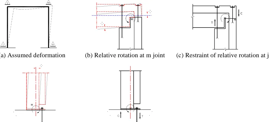
(a) Assumed deformation (b) Relative rotation at m joint (c) Restraint of relative rotation at j joint
M
!
" #
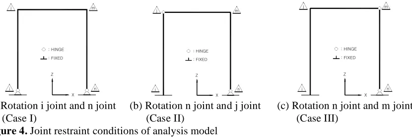
and bolt connection force conditions at the joint point of each member are shown in Fig. 3 (b), (c), (d) and (e). The main load for the shielding block design is the seismic load. This external force can be acted in all directions. Therefore, the analysis models of 3 cases are made, in which the joint point condition as shown in Fig. 4 is considered for obtaining the maximum response results.
! " # $ % & '()*+,-'(.*!-/ ! " # $ % & '()*+,-'(.*!-/ ! " # $ % & '()*+,-'(.*!-/
(a) Rotation i joint and n joint (b) Rotation n joint and j joint (c) Rotation n joint and m joint (Case I) (Case II) (Case III)
Figure 4. Joint restraint conditions of analysis model
3.2 Material properties
The main material properties for the shielding blocks in structural point of view are presented in Table 1. Polyethylene is considered as non-structural material.
Table 1. Main material properties of shielding block
Elastic Modulus (kgf/cm2)
Possion’s Ratio
Specific Weight (tonf/m3)
Strength (kgf/cm2)
Steel (KS D3503 SS400) 2.04x10⁶ 0.3 7.85 2400
Concrete(HC3.5-4.0B4C) 2.35x10⁵ 0.17 3.50 240
3.3 Loads and load combination
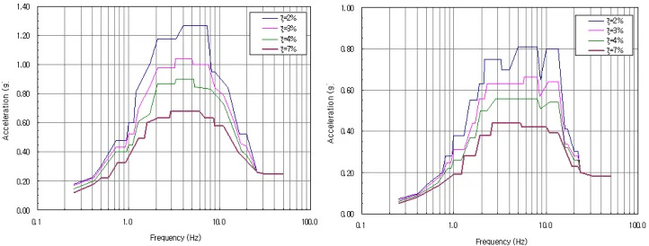
Dead weight (D) is a total weight of all the elements calculated considering the specific weight. The design live load (L) of the 500kgf/m2 is only applied to the roof. The seismic live loads are defined as the mass corresponding to the 25% of the applied live load and considered as the node mass at the node of the analysis model. The floor response spectrum as a seismic load (E) at the reactor hall floor SSE was used. This spectrum had been made when the HANARO reactor building was designed. The structural damping values were applied to the 7% of the critical damping values used at the steel frame structure jointed by the bolts. The horizontal and the vertical floor response spectrum are shown in Fig. 5. The load combinations for the shielding block design were performed according to the AISC Specification 7-05, section 2.3.2 for steel structures and ACI Code 349 section 9.2 for concrete structure. Load combinations are as follows;
COMBO1 : 1.0D + 1.0L + 1.0Ex COMBO2 : 0.9D + 1.0Ex COMBO3 : 1.0D + 1.0L + 1.0Ey COMBO4 : 0.9D + 1.0Ey COMBO5 : 1.0D + 1.0L + 1.0Ez COMBO6 : 0.9D + 1.0Ez
Figure 5. Horizontal and vertical floor response spectrum
3.4 Seismic analysis for shield blocks
The seismic analysis for the shield blocks was performed by using the response spectrum analysis method and the SAP 2000 code. The shielding blocks which are consisted of steel, concrete and polyethylene are converted as the equivalent beam element. These equivalent beam elements have the axial rigidity, the bending rigidity and the torsion rigidity with respect to two axises. On the other hand, the polyethylene was considered as the non-structural element. Therefore, it was excepted when calculating the rigidity of element. The analysis model for the shielding block is shown in Fig. 6. Analysis models of 3 cases according to the restrained joint conditions are shown in Fig. 4.
The configuration of the cross section for the shielding block is shown in Fig. 7. The cross section characteristics values (cross section area, second moment of area, section modulus and radius of gyration) for the 3 types (section A, B and C) were calculated. Also, the weight of shielding blocks were calculated and used as the input of the analysis models.
!"#$%&"#'()&* !"&+&(&#,"#'()&*
-&"./01 234"./01
*565%"+5#7
8 9
STEEL PLATE
Con'c STEEL PLATE
3-3
2-2
INNER STEEL
OUTER STEEL
ts1 tc ts2
Figure 6. Frame model for shielding block Figure 7. Cross section shape of shielding block
3.5 Results of seismic analysis
The modal analysis was performed to obtain the dynamic characteristics of the structure. The 3 cases (Case I, II and III according to the support conditions) with respect to the 3 types (section A, B and C according to the shielding block configuration) were calculated respectively. From the calculated results, the basic natural frequencies were 20 Hz through 25 Hz.
The configuration of 3D finite element model is made additionally in order to calculate the maximum displacement of the shielding block. The maximum displacement of the shielding block is 0.363 mm within the allowable displacement, 5 mm.
The detailed design was performed for each structural element based on the result data obtained from the seismic analysis for the shielding blocks.
3.6.1 Shielding blocks
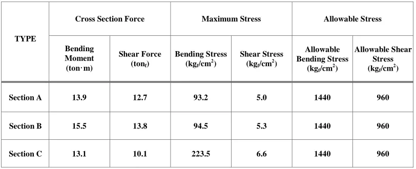
The maximum stress and the allowable stress for the resultant cross section of the shielding blocks connected by the weld are shown in Table 2. The analysis results show that the maximum stresses are within the code limits.
Table 2. Maximum stress and allowable stress for shielding blocks
Cross Section Force Maximum Stress Allowable Stress
TYPE
Bending Moment (ton·m)
Shear Force (tonf)
Bending Stress (kgf/cm2)
Shear Stress (kgf/cm2)
Allowable Bending Stress
(kgf/cm 2
)
Allowable Shear Stress (kgf/cm
2
)
Section A 13.9 12.7 93.2 5.0 1440 960
Section B 15.5 13.8 94.5 5.3 1440 960
Section C 13.1 10.1 223.5 6.6 1440 960
3.6.2 Connection bolts
The structural integrity of connection bolts are evaluated from the results of member forces of them. The required diameter of connection bolts is 48 mm. This diameter is also the same diameter of the lifting eye bolt of the walls. The tap holes of the connection bolt are used for the lifting eye bolts. The calculated stresses of the connection bolts were below the allowable stresses.
3.6.3 Anchor bolts
Based on the results of the member forces of the anchor bolts, the member diameter (36 mm) and embed depth (470 mm) of the anchor bolt were determined in accordance with the failure mechanism of the concrete, ACI 349.
3.6.4 Lifting eye bolts
The maximum weight of the shielding blocks is 21 ton. Number of the lifting eye bolts was determined according to the weight. The required diameters of lifting eye bolts are 48 mm for wall and 64 mm for roofs. The calculated stress ratios of the lifting eye bolts were below the allowable value, 1.
3.6.5 Polyethylene casemate
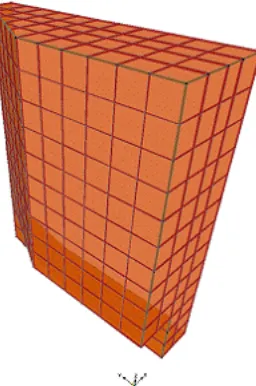
To evaluate the structural integrity of only polyethylene casemate, 3D finite element model was made and the seismic analysis was performed. This model is shown in Fig. 8. The dead weights for the polyethylene and the casemate were divided as the nodal load and the nodal point mass. The maximum value of the floor response spectrum for SSE at the reactor hall floor was applied as the seismic loads (two horizontal directions: 0.68g, vertical direction: 0.45g).
Figure 8. Finite element model for polyethylene casemate
The analysis results for the polyethylene casemate are shown in Table 3. The tensile and shear stress applied to the polyethylene casemate at the time of the seismic generation are below the allowable stresses. The maximum displacement is 0.288 mm and is smaller than 15 mm of the allowable displacement for primary shutter interference.
Table 3. Maximum stress for polyethylene casemate
Maximum Stress(kg/cm2
) Allowable Stress(kg/cm2
)
Tensile Stress Shear Stress Tensile Stress Shear Stress
Max. Displacement (Ux)(mm)
437. 6.2 2280. 1386. 0.29
3.6.6 Foundation slab
The structural integrity evaluation was performed for the foundation slab at which the shielding block is located. The foundation slab supports the reactor building wall, CNS instrument room and reactor pool wall.
(1) Analysis model
The finite element model for the foundation slab is shown in Fig. 9(a). The main loads applied to the structure are the dead weight, the live load and the seismic load. The weight of the wall and roof of the reactor building, the internal CNS instrument room and the shielding block were calculated. The CNS instrument room is supported by 5 columns and the wall body. The reactor pool load is divided equally as nodal point loads at 12 nodal points.
The dead weight of the foundation slab is calculated automatically in the computer program by the definition of the specific weight. The seismic loads as the maximum value among the reaction force obtained from the response spectrum analysis for shielding blocks were applied in the vertical direction at the location of shielding block. The loads applied to the foundation slab are shown in Fig. 9(b). The load combination for the seismic analysis of the foundation slab was performed according to ACI Code 349 as follows;
LC1 = 1.4D + 1.7L
.(a) Finite element model (b) Wall weights (c) Reaction force of S.B
Figure 9. Foundation slab
(2) Results of analysis
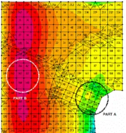
The stress distributions of the N-S and E-W directions for the
foundation slabare shown in Fig. 10.
The part A in the figure is the region at which the shielding blocks are installed. The seismic
analysis results of the
foundation slabwere reviewed with a structural integrity point of view. These
summaries are shown in Table 4.
(a) N-S direction (b) E-W direction
Figure 10. Stress distributions for the foundation slab
Table 4. Safety margin of the reinforced bar for the
foundation slabRegion Direction Layout of R. B. Used R. B. (cm2
)
Req. R. B. (cm2
)
Margin (%)
A D32@3001)
26.473 14.653 45%
C
N-S
D32@150 52.947 34.96 34%
A D32@3001) 26.473 10.21 61%
B
E-W
D32@150 52.947 24.94 53%
Note : 1) Existing R. B. : D32@150, R. B.=Reinforced Bar
installing the support anchors. As shown in Table 4, the safety margins of the reinforced bar in the
N-S and E-W directions at the region A are steel 45% and 61% respectively.
4 CONCLUSIONS
To evaluate the structural integrity for the shielding blocks which are installed around the primary
shutter and neutron guides, the seismic model for the shield blocks was made and the seismic
analysis was performed. From the modal analysis for the 3 types (section A, B and C according to
the shielding block configuration), the basic natural frequencies were 20 Hz through 25 Hz. 3D
finite element model was made additionally in order to calculate the maximum displacement for the
shielding block. The maximum displacement for the shielding block is 0.363 mm. This value is
below the 5 mm of the allowable displacement. The calculated stresses for the shielding block and
the lifting eye bolts were below the allowable stresses. The diameter of the connection bolt was
chosen with larger than that obtained from the structural calculation results. The member diameter
and embed depth of the anchor bolt design was determined in accordance with the mechanism of
ACI 349. It was identified that the tension and shear stress applied to the polyethylene casemate
were below the allowable stress. Also, the seismic analysis results for the foundation slab show that
there is a sufficient margin at the cutting part of the reinforced bar for the installation of the support
anchor bolts. Therefore, the structural integrity for the shielding blocks and related structures was
evaluated.
Finally the detailed design was performed for each structural element by using the result data based on the seismic analysis for the shielding blocks.REFERENCES
Ryu, J.-S., et al., Technical Requirements for Fabrication and Installation of Removable Shield for CNRF in HANARO, KAERI/TR-3573/2008, 2008.4.
ACI 349, Building Code Requirements for Nuclear Safety Related Concrete Structures and Commentary ACI 318, Building Code Requirements for Structural Concrete and Commentary
AISC Specification, Manual of Steel Construction - Allowable Stress Design
ASCE Standard 4-98, Standard for Seismic Analysis of Safety-Related Nuclear Structures and Commentary ASCE Standard 7-05, Minimum Design Loads for Buildings and Other Structures
USNRC, Regulatory Guide 1.29 USNRC, Regulatory Guide 1.61