Parametric Analysis of Multiple U Slot
Microstrip Patch Antenna for Wireless
Applications
Vikram Thakur1, Sanjeev Kashyap2
M.Tech Student, Department of ECE, Green Hills College of Engineering, Solan, India1 Assistant Professor, Department of ECE, Green Hills College of Engineering, Solan, India2
ABSTRACT
:
Antenna is device which is used to transmit and receive electromagnetic waves. It is important to have small antenna which can be useful for mobile applications. In order for antenna to be useful for mobile applications, it is necessary to have small size and antenna. Design and simulation has been carried out using HFSS simulation software. In this dissertation, slots have been cut on side of patch so as to obtain better characteristics; initially patch of length 30 mm is taken and analyzed using coaxial feed at (1, 13, 0).U slots cut in patch is having length of 6 mm and two mm wide. Two straight arms are surrounding it with dimensions of 1x 8 mm2. This u slot is repeated for four sides. . By cutting four u slots, antenna resonated at 4.6 GHz, 5.2 GHz and 7.4 GHz with return loss of 19.81 dB, -11.10 dB and -18.1 dB with bandwidth of 200 MHz, 100 MHz and 800 MHz Parametric analysis had been done in terms of antenna parameters like substrate change, feed length, dimensions of patch and feed point variation.KEYWORDS: Fractal, Slot antenna, Dielectric, Microstrip, DGS
.
I.INTRODUCTION
Nowadays communication plays an important role in the worldwide society and the communication systems are rapidly changing from wired to wireless. Communication can be broadly defined as the transfer of information from one point to another. A communication system is usually required when the information is to be conveyed over a distance. The transfer of information within the communication system had commonly achieved by superimposing the information signal onto high frequency carrier to form an electromagnetic wave. At the required destination, the modulated signal was then received and the original information signal can be recovered by demodulation. Over the years, techniques have been developed for this process using electromagnetic carrier waves operating at radio frequencies as well as microwave frequencies [6]. In high performance point to point application where size, weight, cost, performance and ease of installation are very much required, microstrip antennas are preferred. They are currently one of the fastest growing segments in the telecommunications industry. Since early days, there has been tremendous worldwide activity aimed to develop an efficient antenna. The patch antennas have been used in various fields such as mobile communication, radar, GPS system, Bluetooth, space technology, aircraft, missiles, satellite communication etc. Narrow bandwidth and low gain are two major disadvantages that limit the applications of microstrip antennas. Thus, the size reduction with gain and bandwidth enhancement has become a major consideration in the microstrip patch antennas. Several techniques have been suggested to improve the bandwidth and gain of microstrip antenna [3].
II.LITERATURE SURVEY
ISSN (Print) : 2320 – 3765 ISSN (Online): 2278 – 8875
I
nternational
J
ournal of
A
dvanced
R
esearch in
E
lectrical,
E
lectronics and
I
nstrumentation
E
ngineering
(An ISO 3297: 2007 Certified Organization) Vol. 4, Issue 3, March 2015
antenna geometry structures. In order to make these antennas two materials namely flectron and zeit had been used. Textile materials that were used were namely Flectron and Zeit. Polyster fibre material had been used as dielectric material. Chouiker et al[4] proposed antenna by making use of fractal geometry. This antenna had been used for multiple inputs and multiple output system. This antenna most commonly found application for handheld mobile devices. This structure was made of Minkowski island curve and Koch fractal curve.
Verma et al. [5] proposed novel microstrip fractal antenna using Minkowski fractal curve. This antenna had been used by taking FR-4 as substrate. Minkowski fractal geometry had been used. This antenna had application for GSM900/1710/GPS1227/1575/WiMAX2500and IEEE802.11b standard applications. Nagpal A et al. [6].proposed E-shaped fractal Microstrip patch antenna with defected ground structure for wireless applications. By applying the different type of iterations of fractal geometry self-similar E shape structures are obtained. For obtaining good bandwidth, Different DGS configurations had been applied Lee et al.[7] proposed an ordinary patch antenna in the form of simple resonant circuit. This antenna had feature that its resonance frequency gets lowered by increasing number of slots without making change in capacitance. This antenna provided low cost solution which has been useful for applications of short range two way communications. Nasimudin et al.[8] circular polarized slotted patch antenna for global navigation satellite system application. This antenna was having square ring with vias. Four square ring shaped slots were cut out onto square patch along diagonal sides and size reduction. This antenna had compact size of 60 X60 X 5 mm3 .
III. ANTENNA DESIGN
Microstrip antenna had been used for number of applications, Because of their limitations like less bandwidth and gain, these antenna are not very useful. Hence in order to remove these disadvantages, techniques have been introduced like cutting of slots. Parametric analysis has been carried out in order to have best antenna parameters. There are different antenna parameters which can be improved. This antenna has been size of substrate of 50 by 50 mm, height of 2.4 mm. Dimensions of antenna have been shown in table 1.
Table 1: Antenna Dimensions
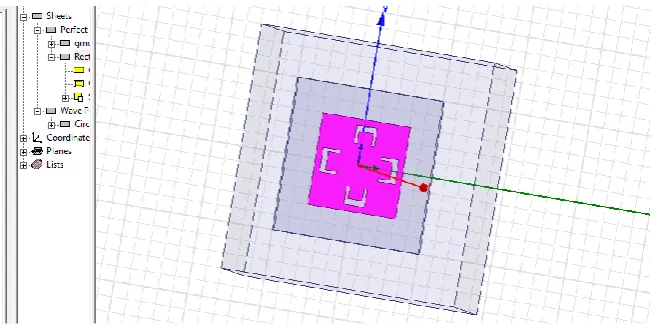
There are slots cut to form u slots. All these parameters can be verified in order to improve antenna characteristics. Feed is made by having outer radius of 0.48 mm and inner radius of 0.24 mm. Feed to antenna is made by given excitation through port cap with dimensions same as outer cylinder and height of 0.24 mm. Entire antenna is given boundary as radiation boundary to find antenna parameters. Design of zeroth iteration has been shown in figure 1.
Variable Value
Dimensions of Patch 30 X 30 mm2 Dimensions of Ground 50 X 50 mm2 Thickness of Substrate 2.4 mm
Feeding technique used Coaxial Feeding Technique Substrate used FR-4
Figure 1: Initiatior Antenna
After designing basic configuration, one may also get simple u slot to obtain better characteristics. In case of reference antenna one has patch of size 32X 30 mm2. Instead of designing antenna with same dimensions as that of antenna one cut u slot in patch of size 30 mm. U slots cut in patch is having length of 6 mm and two mm wide. Two straight arms are surrounding it with dimensions of 1x 8 mm2. Final iteration is applied by increasing number of slots up to four. These slots have all same dimensions. Slots have been cut in form of ring. It is found that as number of slots increases, characteristics of antenna improves in terms of return loss, bandwidth and gain. Geometry of four u slot antenna has been shown in figure 2.
Figure 2: Four U slot Antenna
From these iterations, it is found that final iteration is produced from first iteration, by cutting of slots. Three slots have been cut out to form u slot antenna. By increasing number of slots, two three, four u slot antenna have been obtained. Parametric analysis has been carried out in order to have that antenna which gives best result.
ISSN (Print) : 2320 – 3765 ISSN (Online): 2278 – 8875
I
nternational
J
ournal of
A
dvanced
R
esearch in
E
lectrical,
E
lectronics and
I
nstrumentation
E
ngineering
(An ISO 3297: 2007 Certified Organization) Vol. 4, Issue 3, March 2015
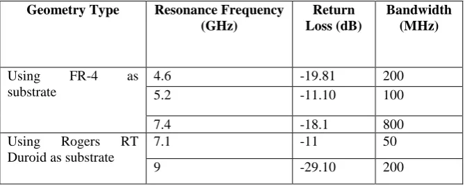
antenna resonated at 4.6 GHz, 5.2 GHz and 7.4 GHz with return loss of -19.81 dB, -11.10 dB and -18.1 dB with bandwidth of 200 MHz, 100 MHz and 800 MHz. This antenna had good gain of 5.10 dBi, 3.2 dBi and 6.3 dbi at corresponding frequencies. By using RT-Duroid 5880 as substrate, antenna resonated at 7.1 GHz and 9 GHz with return loss of -11 dB and – 29 dB with bandwidth of 50 MHz and 200 MHz Return loss versus frequency for different substrate configurations has been shown in figure 3.
Figure 3: Return Loss Vs. Frequency for Multi U Slot Antenna with Different substrates
Rogers RT Duroid is having dielectric constant of 2.2 and loss tangent of 0.0009. FR-4 is having dielectric constant of 4.4 and loss tangent of 0.02. Characteristics of both antennas with different substrate have been compared in table 2.
Table 2: Antenna Characteristics of Different Substrate Configurations
By using coaxial feed, antenna is given feed at (1, 13, 0). Antenna is fed by microstrip line with feed length of 2mm and width of 10 mm. By using microstrip line feeding technique, antenna resonated at 2.3 GHz, 4.5 GHz, 6.1 GHz and 9.7 GHz with return loss of -11.33 dB, -12.47 dB, -14.13 dB and -13.11 dB. This antenna had bandwidth of 100 MHz, 210 MHz, 110 MHz and 90 MHz at corresponding frequencies. Return loss versus frequency curve for different feeding techniques have been compared in figure 4. It is found that number of bands improved by making use of coaxial technique. Comparison has made in terms of antenna parameters as shown in table 3. By using coaxial feed at (1,13,0), antenna resonated at 4.6 GHz, 5.2 GHz and 7.4 GHz with return loss of -19.81 dB, -11.10 dB and -18.1 dB with bandwidth of 200 MHz, 100 MHz and 800 MHz These show better results can be obtain after performing parametric analysis.
Geometry Type Resonance Frequency (GHz)
Return Loss (dB)
Bandwidth (MHz)
Using FR-4 as substrate
4.6 -19.81 200 5.2 -11.10 100 7.4 -18.1 800 Using Rogers RT
Duroid as substrate
Figure 4: Return Loss Versus Frequency For Microstrip Fed Antenna
Characteristics of antenna are compared in terms of antenna parameters return loss and bandwidth as in table 3. The blue line corresponds to that of coaxial probe and pink line corresponds to that of microstrip feed.
Table 3: Antenna Characteristics of Different Feeding Techniques
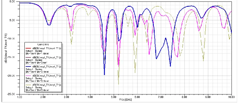
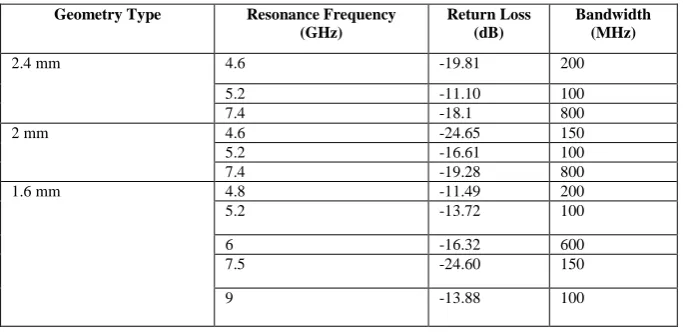
Results are analyzed by analyzing effect of changing substrate. It is found that by increasing substrate thickness, bandwidth of antenna increases. Effect of varying substrate thickness has been analyzed and antenna is designed for different thickness. Antenna has been designed for three different thickness. Characteristics obtained for height 1.6 mm, 2 mm and 2.4 mm are compared in table 4.
Table 4: Antenna Characteristics of Different Substrate Thickness
Geometry Type Resonance Frequency
(GHz)
Return Loss (dB)
Bandwidth (MHz)
Using coaxial feed 4.6 -19.81 200
5.2 -11.10 100
7.4 -18.1 800
Using Microstrip Feed 2.3 -11.33 100
4.5 -12.47 210
6.1 -14.13 110
9.7 -13.11 90
Geometry Type Resonance Frequency
(GHz)
Return Loss (dB)
Bandwidth (MHz)
2.4 mm 4.6 -19.81 200
5.2 -11.10 100
7.4 -18.1 800
2 mm 4.6 -24.65 150
5.2 -16.61 100
7.4 -19.28 800
1.6 mm 4.8 -11.49 200
5.2 -13.72 100
6 -16.32 600
7.5 -24.60 150
ISSN (Print) : 2320 – 3765 ISSN (Online): 2278 – 8875
I
nternational
J
ournal of
A
dvanced
R
esearch in
E
lectrical,
E
lectronics and
I
nstrumentation
E
ngineering
(An ISO 3297: 2007 Certified Organization) Vol. 4, Issue 3, March 2015
From characteristics obtained, it is found that better results are obtained for thickness of 1.6 mm but as thickness increases, although number of bands at which antenna resonated decrease but bandwidth and gain of antenna improves. Return loss versus frequency for different height antenna has been shown in figure 5.
Figure 5: Return Loss versus Frequency Antenna with Different Substrate Thickness
Feed to antenna had been given at x=1 mm and y= 13 mm, x=3 mm, y=13mm and x=5 mm. It is found that at x=1 antenna resonated at three bands with good bandwidth of 800 MHz at one band. At x=5 mm, antenna resonated at 5 different bands at 3.2, 4.6, 5.2 and 5.6 GHz bands. This antenna had been useful for different wireless applications, but bandwidth of antenna is small. Hence different such combinations can be made by moving feed at different points on antenna.
Table 5: Antenna Characteristics of Different Feed Points
1.00 2.00 3.00 4.00 5.00 6.00 7.00 8.00 9.00 10.00
Freq [GHz] -25.00 -20.00 -15.00 -10.00 -5.00 0.00 d B(S t(i n cyl _ T 1 ,in cyl _ T 1 )) HFSSDesign1
XY Plot 14 ANSOFT
Curve Inf o dB(St(incyl_T1,incyl_T1)) Setup1 : Sw eep $h='1.6mm'
dB(St(incyl_T1,incyl_T1)) Setup1 : Sw eep $h='2mm'
dB(St(incyl_T1,incyl_T1)) Setup1 : Sw eep $h='2.4mm'
Geometry Type Resonance Frequency
(GHz)
Return Loss (dB)
Bandwidth (MHz)
Feed at x=1, y=13 4.6 -19.81 200
5.2 -11.10 100
7.4 -18.1 800
Feed at x=5, y=13 3.2 -11.59 50
4.6 -19.95 200
5.2 -22.31 100
5.9 -19.24 200
6.4 -11.05 30
7.8 -14.76 300
8.8 -16.1 150
Feed at x=3, y=13 4.6 -13.72 300
5.2 -17.35 200
6.5 -14.27 200
Return loss versus frequency curve for different antenna configurations fed by coaxial feed has been shown in figure 6. It is found that best results obtained at x=1 mm. This antenna can be used for different wireless applications such as Wi-Max and WLAN applications.
Figure 6: Return Loss versus Frequency for Antenna with Different Feed
V. CONCLUSION
It has been concluded that Design and simulation has been carried out using HFSS simulation software. In this dissertation, slots have been cut on side of patch so as to obtain better characteristics; initially patch of length 30 mm is taken and analysed using coaxial feed at (1, 13, 0).U slots cut in patch is having length of 6 mm and two mm wide. Two straight arms are surrounding it with dimensions of 1x 8 mm2. This u slot is repeated for four sides. . By cutting four u slots, antenna resonated at 4.6 GHz, 5.2 GHz and 7.4 GHz with return loss of -19.81 dB, -11.10 dB and -18.1 dB with bandwidth of 200 MHz, 100 MHz and 800 MHz Parametric analysis had been done in terms of antenna parameters like substrate change, feed length, dimensions of patch and feed point variation.
VI. ACKNOWLEDGMENT
I am thankful to our Green Hill engineering college and HOD of ECE deptt. And my supervisor Er. Sanjeev kashyap Sir who supported and guided me for this work.
REFRENCES
1. Nagpal A., Singh S. and Marwaha A. “Multiband E-Shaped Fractal Microstrip Patch Antenna with DGS for Wireless Applications”,
“Proceedings of 5th IEEE International Conference on Computational Intelligence and CommunicationNetworks”, Mathura, India, 2013. 2. Varadhan C., Pakkathillam J. Kizhekke, Kanagasabai M., Sivasamy R., Natarajan R. and Palaniswamy S. Kumar. “Triband Antenna structures
for RFID Systems Deploying Fractal Geometry”, “IEEE Letters on Antennas and Wireless Propagation”, Vol. 12, pp 437-440, 2013.
3. Janani. A, Priya. A. “Design of E-Shape Fractal Simple Multiband Patch Antenna for S-Band LTE and Various Mobile Standards”, “International Journal of Engineering and Science”, Vol. 3, Issue 1, pp 12-19, 2013.
4. Ojaroudi M., Ojaroudi, N., Ghadimi, N. “Dual Band-Notched Small Monopole Antenna with Novel Coupled Inverted U-Ring Strip and Novel Fork-Shaped Slit for UWB Applications”, “IEEE Antennas and Wireless Propagation Letters”, Vol. 12, pp. 182-185, 2013.
5. Behera S. and Vinoy K. J. “Multi-Port Network Approach for the Analysis of Dual Band Fractal Microstrip Antennas”, “IEEE Transactions on Antennas and Propagation”, Vol. 60, No. 11, pp 5100-5106, 2012.
6. Ram V., Anjaria V., Boriya P. and Patel N. “Design and Development of Switchable Fractal Patch Antenna for GPS Application”, “International Journal of Engineering and Science”, Vol. 1, Issue. 7, pp 46-50, 2012
7. Nasimuddin, 2014, “Slotted microstrip antennas for circular polarization with compact size”, IEEE Antenna And Wireless Propagation Letter,
Vol. 55, pp 127-34
8. Liu H., 2014, “Single feed slotted bowtie antenna for triband application”, IEEE Antenna And Wireless Propagation Letter, Vol. 12, pp 1658-61.
![Figure 5: Return Loss versus Frequency Antenna with Different Substrate Thickness Freq [GHz]](https://thumb-us.123doks.com/thumbv2/123dok_us/7789154.1289876/6.595.143.456.458.738/figure-return-versus-frequency-antenna-different-substrate-thickness.webp)