Analysis of Self Excited Capacitances for Self
Excited Induction Generator for Different
Operating Conditions Using Fuzzy Systems
Sujata Gaur1, Bandana2
Assistant Professor, Dept. of EEE, Krishna Engineering College, Ghaziabad, India1
Assistant Professor, Dept. of EEE, Krishna Engineering College, Ghaziabad, India2
ASTRACT:- Self-excited induction machine seem to be the most suitable generators for wind energy conversion in
remote and windy areas. Steady state analysis for such machines is essential to estimate the behaviour under actual operating conditions. Excitation analysis of a three phase self excited induction generator feeding balanced unity power factor load is proposed. Iterative technique has been used to find the generated frequency. When load and speed is increased then value of capacitance and generated frequency are calculated keeping Xm fixed. It is observed that the value of capacitance is decreasing with increase in load and speed and value of frequency is decreasing. Then fuzzy system is applied to these values of Self excited induction generator (SEIG). Simulation results showed the effectiveness of the proposed work.
KEYWORDS:Self-exited induction generator; magnetization characteristics; fuzzy system.
I.INTRODUCTION
For the machine to self-excite, the excitation capacitance must be larger than some minimum value. In order to obtain a stable output voltage, the machine must operate at an appreciable level of magnetic saturation. Accordingly, the magnetizing reactance Xm is not constant, but varies with the load and circuit conditions. For successful voltage build-up, the load-capacitance combination should result in a value of Xm which is less than the unsaturated value, hence the condition Xm = Xmax yields the minimum value of excitation capacitance below which the SEIG fails to self-excite. There are two different approaches in the steady-state analysis of self-excited induction generators. They are the loop impedance method as used by Malik et al and the nodal admittance method as used by Mcpherson et al. If the machine speed is specified and the condition Xm = Xmax prevails, then the only variables in the equivalent circuit are the per- unit frequency f and the capacitive reactance Xc.
The nodal admittance method will be used instead, the advantage being that the load and excitation capacitance branches can be easily decoupled, which enables the per unit frequency f to be determined independent of the value of Xc.
II
.
CAPACITOR SELF-EXCITATION, ANALYSISThe equivalent circuit commonly used for the steady-state analysis of the SEIG [1] is shown in figure 1. For the machine to self-excite, the excitation capacitance must be larger than some minimum value. In order to obtain a stable output voltage, the machine must operate at an appreciable level of magnetic saturation. Accordingly, the magnetizing reactance Xm is not constant, but varies with the load and circuit conditions. For successful voltage build-up, the load-capacitance combination should result in a value of Xm which is less than the unsaturated value, hence the condition Xm = Xmu yields the minimum value of excitation capacitance below which the SEIG fails to self-excite.
There are two different approaches in the steady-state analysis of self-excited induction generators. They are the loop impedance method as used by Malik et al. [1,5] and the nodal admittance method as used by McPherson et al. [8]. If the machine speed is specified and the condition Xm = Xmu prevails, then the only variables in the equivalent circuit of figure 2 are the per- unit frequency f and the capacitive reactance Xc.
The nodal admittance method will be used instead, the advantage being that the load and excitation capacitance branches can be easily decoupled, which enables the per unit frequency f to be determined independent of the value of Xc
Figure 1: Equivalent circuit of SEIG
For this purpose, figure 3 is redrawn as figure 4, where
= ( )+ // (1)
Separating real and imaginary parts
= (( ) ()
) (2)
= ( ) . ( )
( ) ( ) (3)
The total impedance of branch acd is then given by
= + (4)
= + (5)
= + (6)
= +
The admittances and are given by
=
−
(7) = − (8)By Kirchhoff’s Law, the sum of current at node ‘a’ should be equal to zero, hence
V1( + + ) = 0 (9)
For successful voltage build-up, ≠0, hence
+ + = 0(10)
Equating the real and imaginary part to zero
+
= 0
(11)−
−
= 0
(12)It is noted that (11) is independent of Xc& the only variable is the per unit frequency f. Once the value of f has been
determined the Xc can be determined using (12).
Equation (11), after a series of algebraic manipulation can be expressed as a 6th degree polynomial in f is
+ + + + + + = 0 (13)
The derivation of these constant (coefficients) P0 to P6 are given below. Equation (13) can be solved numerically to
yield the entire real and complex root. Only the real root have physical significance and the largest positive real root yields the per unit frequency that corresponds to Cmin i.e.
= { , ≤6} (14)
Where { , ≤6} is the set of positive real root of (13)
Having determined equation (12) may be used to calculate Cmin as follows:
= + (15)
To compute the coefficient P0 and P6, the following are first defined;
= + (16)
= + ( − ) (17)
1 = + ( − ) (18)
2 = [ + { + ( − ) }] (19)
Equating (11), upon cross-multiplication, becomes
( 1 + 2 ) + ( + ) . 1 = 0(21)
DENOM, NUM1 and NUM2 can be reduced to the following forms:
= + + (22)
1 =ℎ +ℎ +ℎ (23)
2 = + + (24)
Where
= +
=−2
=
(25)
ℎ = ( + )
ℎ =− ( + 2 )
ℎ = +
(26)
= ( + ) + ( + )
=−2 ( + ) =−2
= +
(27)
Each of the terms in (11), after expansion reduces to a 6th degree polynomial, whose coefficient P0 to P6 are given
below:
= + ℎ
= ℎ + ℎ + 2
= (ℎ + + 2 ) + ( ℎ + + ℎ) + ℎ
P3 = (g1 h0 + g0 h1) X2 + ( ℎ + ℎ) + (2ℎ ℎ + 2 )
= ( ℎ + ℎ + ℎ) + ℎ + (ℎ + + 2ℎ ℎ )
P1 = ( ℎ + h1) R2 + 2 h0 h1 R
=ℎ + ℎ
The coefficients P0 and P6 are systematically expressed in terms of R, X and the constants defined in (25) to (27)
For resistive load
Substitute X=0 in (16) to (27). The modified coefficients are as follows: =
= 2
= (ℎ + + 2 ) + ℎ
= ( ℎ + ℎ ) + (2ℎ ℎ + 2 )
= ( ℎ + ℎ + ℎ ) + (ℎ + + 2ℎ ℎ )
P1 = ( ℎ + h1) R2 + 2 h0 h1 R
=ℎ + ℎ
III.COMPUTED AND EXPERIMENTAL RESULTS
In this paper computed and experimental results refer to three phase,4 pole,50 Hz star connected squirrel cage induction machine, 750KW/1HP, 380V, 1.9A whose per phase equivalent circuit constants in per unit are as follows:
Rs=.0823p.u, Rr=.06967p.u, Xs= Xr =.0766p.u
Non linear relationship between Xm and E1 using experimental data for machine may be represented by PLA as below:
E1=2.3378-1.12 Xm Xm<1.466
E1=4.066-2.3 Xm 1.5547≤Xm≥1.466
E1=3.583-1.989 Xm 1.5984≤Xm≥1.554
E1=0 Xm>1.5984
Now Xm is fixed.
When Xm is fixed capacitance is calculated for different load and speed.
R(Ω) b(r.p.m) a(Hz) C(μf) 200 1450 46.025 29.765 220 1460 46.55 28.57 235 1465 46.835 27.92 250 1490 47.1 27.33 262 1480 47.495 26.7 275 1490 47.895 26.09 282 1500 48.26 25.615 295 1510 48.615 25.1 305 1530 49.345 24.276 318 1442 49.795 23.73 326 1550 50.07 23.4 345 1560 50.49 22.88 360 1570 50.865 22.45 380 1575 51.095 22.13 400 1600 51.94 21.33 420 1635 53.175 20.277 435 1650 53.7 19.83
Table-1: Calculated data of SEIG
A fuzzy modelling is developed to determine the generated frequency and excitation capacitance of the IG according to the rotor speed and desired value of load resistance of the Induction Generator (IG) using the values given in table-1.Considering the possible parameter variations of the IG , a fuzzy control rule using the desired speed and load resistance as the linguistic variable in the antecedent part and the generated frequency, capacitance as the variable in the consequent part is derived first. The proposed membership functions can be described. The linguistic values, membership functions, fuzzy control rules and defuzzification of the proposed modelling as chosen as follows:
IV.BASIC STRUCTURE OF FUZZY LOGIC
Two inputs: Load and Speed
Load range: 200Ω - 435Ω
Low: 200 – 220 – 250 Med: 235 – 275 – 305 High: 295 – 345 – 380 Very high: 360 – 400 – 435 Speed range:1450-1650r.p.m
Low: 1450 – 1460 – 1470 Med: 1465 – 1490 – 1510 High: 1500 – 1550 – 1575 Very high: 1570 – 1600 – 1650 Two outputs: frequency and capacitance
Very High: 50.490 - 51.940 - 53.700 Capacitance range:19.83-29.765µf
Low: 19.830 - 21.330 - 22.450 Med: 22.130 - 23.400 - 25.100 High: 24.276 - 26.090 - 27.330 Very high: 26.700 - 27.920 - 29.765
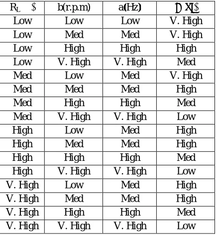
Table 2: Rule base table of input and output data
Linguistic values: Low, Medium, High, Very high. Membership functions: Depending on the special applications and
the performance of the user, many type of membership functions can be selected. In this study, the triangle shaped functions are used [14-18].
Figure 3: Linguistic variables
Construction of fuzzy rules: On the basis of experience and knowledge concerning the IG system to be controlled,
linguistic rules for the fuzzy modelling of IG which are IF-THEN forms are formulated and listed in table-2 . The load resistance and speed are the linguistic variable in the antecedent part and capacitance, generated frequency are the
RL(Ω) b(r.p.m) a(Hz) C(μf)
Low Low Low V. High
Low Med Med V. High
Low High High High
Low V. High V. High Med
Med Low Med V. High
Med Med Med High
Med High High Med
Med V. High V. High Low
High Low Med High
High Med Med High
High High High Med
High V. High V. High Low
V. High Low Med High
V. High Med Med High
linguistic variable in the consequent part.
Figure 4: Rule base for given data .
V. RESULT AND DISCUSSION
Defuzzification: The centroid of area method is implemented to result in the output
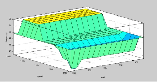
Figure 5: Fuzzy Logic output results of SEIG
Figure 5 shows the fuzzy logic output results of self excited induction generator.As self excited capacitance plays important role in improving voltage regulation, as the value of load and speed changes it affects the value of generated frequency and capacitance .
VI.CONCLUSION
In this paper attempt has been made to realize the value of self excited capacitances and generated frequency for self excited induction generator, when Xm is fixed for the computation of steady state performance of SEIG using iterative
technique. As self excited capacitance plays an important role in improving voltage regulation, as the value of load and speed changes it affects the value of generated frequency and capacitance. In this paper attempt has been made to realize that as the value of load and speed increases, the value of capacitance decreases and generated frequency increases. A close agreement between the computed and experimental results confirms the validity and accuracy of the analysis of SEIG using fuzzy system.
APPENDIX
The details of machine Specifications
3-phase, 4-pole, 50 Hz, star connected, squirrel cage induction machine 0.750kw/1HP, 380V(rated line voltage), 1.90A.
R1=9.5Ω, R2=8.04Ω, X1=X2=8.84Ω
Base voltage=219.30V Base current=1.90A Base impedance=115.40Ω Base capacitance=27.5µf Base power=1.25kw Base frequency=50Hz Base speed=1500 r.p.m
REFERENCES
[1] Murthy.S. S, Malik .O. P, andTan don. A.K. “Analysis of self-excited induction generators,” Proc. IEE,vol. 129,pt. C, no. 6, pp. 260-265,1982.
[2] Riana .G andMalik. O. P, “Wind energy conversion using a self-excited induction generator,” IEEE Trans. Power Apparatus and Systems, vol. PAS-102, no. 12, pp. 3933-3936, 1983.
[3] Tan don .A. K, Murthy.S. S and Jha .C. S, “New method of computing steady-state response of capacitor selfexcited induction generator,” IE(I) Journal-EL, vol. 65, pp. 196-201,1985.
[4] Malik N. H and Haque.S. E, “Steady-state analysis and performance of an isolated self-excited induction generator,” IEEE Trans. Energy Conversion, vol.EC-1, no.3, pp.134-139, 1986.
[5] Malik.N. HandAl-Bahrani A. H, “Influence of the terminal capacitor on the performance characteristics of a self-excited induction generator,” Proc. IEE, vol.137, pt.C, no. 2, pp.168- 173, 1990.
[6] Shridhar.L, Singh .B, andJha. C. S, “A step towards improvements in the characteristics of self-excited induction generator,” IEEE Trans. Energy Conversion, vol. 8, no. 1, pp. 40-46, 1993.
[7] Chan T. F, “Steady-state analysis of self-excited induction generators,” IEEE Trans. Energy Conversion, vol. 9, no. 2, pp.288-296, 1994. [8] Quazene .L andMcPherson. G, “Analysis of the isolated induction generator,” IEEE Trans. Power Apparatus and Systems, vol. PAS- 102, no.
8, pp. 2793-2798, 1983.
[9] Chan .T. F, “Analysis of self-excited induction generators using an iterative method,” IEEE Trans. Energy Conversion, vol. 10 no. 3, pp. 502-507, 1995.
[10] Sandhu .K. S and Jain .S. K, “Operational aspects of selfexcited induction generator using a new model”, Electric Machines and Power Systems, vol. 27, no. 2, pp. 169-180, 1999.
[11] Abdel-Halim .I. A. M,Al-Ahmar. M. A, andEl-Sherif. M. Z, “A novel approach for the analysis of self-excited induction generator,” Electric Machines and Power Systems, vol. 27, pp. 879-888, 1999.
[12] Sandhu .K. S, “Iterative model for the analysis of self excited induction generators,” ElectricPower Components and Systems, vol. 31, no. 10, pp. 925-939,2003.
[13] Chatterjee, J.K., Bansal, Atul, and Sarkar, Dipankar. “Performance evaluation of synchronous impedance controller based self-excited induction generator system,” IEEE CNF, 2006.
[14] Wang .L. X andMendel. J. M, “Generating fuzzy rules by learning from examples,” IEEE Trans. Syst., Man, Cybern. vol. 22, pp. 1414–1427, 1992.
[15] Rovatti .R. andGuerrieri. R, “Fuzzy sets of rules for system identification,” IEEE Trans. Fuzzy Syst., vol. 4, pp. 89–102, 1996.
[16] Abe .S and Lan .M. S, “Fuzzy rules extraction directly from numerical data for function approximation,” IEEE Trans. Syst., Man, Cyber. vol. 25, pp. 119–129, 1995.