Transmission Cable Type As A Function Of Effective And
Safe Power Utilization In An Electrical Circuit
Familusi, T.O1, Raimi, A.M2,Abioye, I.O3, Alaje, E.O4 andYusuf G. T.5
1
Department of Science Laboratory Technology, Osun State Polytechnic, Iree, Nigeria 2
Department of Science Laboratory Technology, Osun State Polytechnic, Iree, Nigeria 3
Department of Science Laboratory Technology, Osun State Polytechnic, Iree, Nigeria4Department of Science Laboratory Technology, Osun State Polytechnic, Iree, Nigeria
5
Department of Science Laboratory Technology, Osun State Polytechnic, Iree, Nigeria
Abstract
In this research, experiments were carried out on the performance of certain common installation cables during which the temperature of each cable was recorded at intervals of 5munites(300seconds) from 0 to 30minutes of consecutive welding operation. A 5.0mm (2x2.5mm) iron China cable labelled as “Sunrise wire & cable” and a 5.0mm carbon-steel cable type were used as a group of cable with a high level of magnetism, while a 5.0mm (2x2.5mm) pure copper cable labelled as “Kable Smart Nigeria wire and cable fire resistance” and a 5.0mm pure aluminium cable (service cable) were used as another cable group that has a negligible or near zero level of magnetism to power a welding machine (ACARC WELDER, Model: BX1-300D, Produce Standard: GB15679.1-20004, frequency: 50Hz, power rate: (220-380V)(100-300A). Heavily covered (coated) electrodes (D/d = 1.45 – 1.80) were used in the experiment as the welding electrodes. The voltages across the arc during welding operations were measured and values obtained are in the range 3.90V to 5.37V with 2.74 to 3.77V and 22.8V to 31.4V with 13.62V to 18.77V respectively for the two cablegroups as power lead cables to the welding machine while current was adjusted within 100A to 300A.The temperature of the cables was also recorded at the same intervals and rang of time. The results show that power loss is enormous with the cable group A, and very lowwith cable group B when they were respectively used as power supply conducting leads connecting the power source and the welding machine.The effect of the results is manifested in the nature of the finished products from the practical welding operations as could be graded in the range zero-, worst-, worse-, bad- and fair-products; and fair-, good-, very good-and excellent/perfect-products respectively for cable group A and cable group B as voltage/current carrying conductors to the welder. The temperature gradients for the two groups of cable used is an upward slope that shows a set of corresponding and normalincrements with the welder current settings for copper cable, and approximately normal increments for aluminium cable; while the increments appear abnormal for the group A cables consisting of iron cable and carbon-steel cable. The results indicate that much power was lost as heat energy in group A cables.
Keywords: Experiment, installation, magnetism, temperature, current and voltage.
Introduction
92
operation leading to an abnormal and unnecessary power dissipation as a wastage (Einstein's theory of special relativity).
Generally, a current is always accomplished by certain magnetic effect. A current carrying conductor placed near a magnetic needle will deflect the needle to a certain direction; and also when the direction of current in the conductor is reversed, the needle will deflect in opposite direction. It means there is a magnetic field due to the current carrying conductor (Danish Physicist, 1819).
The heat loss when current passes through a conductor is directly proportional to the resistance of the conductor, H = I2Rt. That is, the heating of current in a conductor is strictly a function of its resistance. (Joule’s law). An additional magnetism to flow of current via a conductor constitute an undue disturbance to the flow of current. This is the root of the frequent fire hazard in several cities of Nigeria where normal (nonmagnetic) conductor was not used for electrical wiring of structures.
The magnetic flux density of the induced magnetic field around the conductor increases if the current flowing through the conductor is increased and it decreases if the current is decreased (Biot Savart’s law). The gravity of heat effect in a current carrying magnetic conductor enormous when the current is high, which is the characteristic of a high powered machine.
Temperature is certainly an important factor in evaluating equipment. However, if you follow guidelines that are based solely on absolute temperature measurement -or on a temperature rise (Delta T) —you run the risk of incorrectly diagnosing your problems. The consequences of such actions can lead to a false sense of security, equipment failure, fire, and even the possibility of personal injury. Understanding the additional factors involved in diagnosis is essential for obtaining productive results. One of these factors is the load or current flowing through conductors. The load can have a drastic effect on the temperature of a component. Changing loads can cause additional concerns because temperature changes lag behind load changes. The purpose of this paper is to illustrate the relationship between load and temperature of a faulty connection. The thermal response of a changing load is also investigated (Bernard R. et al, 2011)
50Hz, power rate: (220-380V)(100-300A) with a heavily covered (coated) electrode (D/d = 1.45 – 1.80) used in the experimental welding during which the voltages across the arc g welding operations were measured. The temperature of the conducting cables were taken at several intervals.
The current rating or current-carrying capacity, ampacity of a high powered machine is always set very high to withstand cases of abnormal application to exceptionally high current. Ampacity is the RMS electric current which a device or conductor can continuously carry while remaining within its temperature rating That is, the maximum amount of electrical current a conductor or device can carry before sustaining immediate or progressive deterioration. The ampacity of a conductor depends on its insulation temperature rating, the electrical resistance of the conductor material, the frequency of current (in the case of alternating current) and the ability to dissipate heat (which depends on conductor geometry and its surroundings) and the ambient temperature (Wikimedia Project, 2014).
Materials and Methods
The materials used in the experiment include magnetic conductors - 5.0mm (2x2.5mm) iron China cable labelled as “Sunrise wire & cable” with another 5.0mm carbon-steel cable type; magnetic conductors - 5.0mm (2x2.5mm) pure copper cable labelled as “Kable Smart Nigeria wire and cable fire resistance” with another 5.0mm pure aluminium cable (service cable), a welding machine (ACARC WELDER, Model: BX1-300D, Produce Standard: GB15679.1-20004, frequency: 50Hz, power rate: (220-380V)(100-300A), heavily covered (coated) electrodes (D/d = 1.45 – 1.80), power source (mains), welding glasses and other protective materials like rubber hand-gloves. D/d is the ratio of electrode diameter (D) to the bare-rod diameter (d), which gives in fact the thickness of the coating. The normal manual welding method was used throughout the experiment, where the welding machine was perfectly fitted with the earth conductor had full and strong contact with load; and powered via the mains power supply (240V, a.c).The voltages across the arc during welding operations were measured and values obtained are the in range 3.90V to 5.37V with 2.74 to 3.77V and 22.8V to 31.4V with 13.62V to 18.77V respectively for the two magnetic conductors and the two non-magnetic conductors used as power lead cables to the welding machine while current was adjusted within 100A to 300A.The temperatures of the cables were recorded at intervals of 5minutes (300seconds) from 0 to 30minutes.
94
Table 1: The voltages across the arc in the experiment with each cable at different ACARC current ratings.
Machine Current(A) Arc Voltage (V)
Cu cable Al cable Fe cable C –S cable
100 23.20 13.62 3.90 2.74
140 25.42 14.92 4.27 3.01
180 26.91 15.80 4.52 3.18
220 29.73 17.45 5.10 3.51
280 31.60 18.55 5.30 3.73
300 31.98 18.77 5.37 3.77
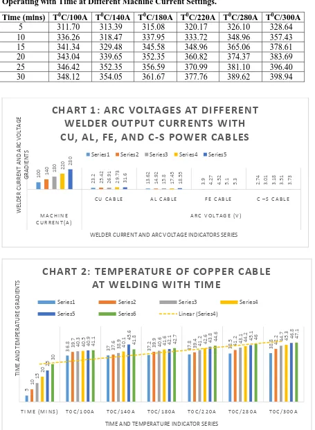
Table 2 (a) Temperature of Non-magnetic Power Supply Cables (copper) under Welding Operating with Time at Different Machine Current Settings.
Time (mins) T0C/100A T0C/140A T0C/180A T0C/220A T0C/280A T0C/300A
5 36.80 37.00 37.20 37.80 38.50 38.80 10 39.70 37.60 39.90 39.40 41.20 42.20 15 40.30 38.90 40.60 41.20 43.10 44.70 20 40.50 40.10 41.60 42.60 44.20 45.30 25 40.90 45.60 42.10 43.80 45.10 46.80 30 41.10 41.80 42.70 44.60 46.00 47.10
Table 2 (b) Temperature of Non-magnetic Power Supply Cables (aluminium) under Welding Operating with Time at Different Machine Current Settings.
Time (mins) T0C/100A T0C/140A T0C/180A T0C/220A T0C/280A T0C/300A
5 62.56 62.90 63.24 64.26 65.45 65.96 10 67.49 63.92 67.83 66.40 70.04 71.74 15 68.51 66.13 69.36 70.04 73.27 75.99 20 68.85 68.17 70.72 72.42 75.14 77.01 25 69.53 70.72 71.57 74.46 76.67 79.56 30 69.87 71.06 72.59 75.82 78.20 80.07
Table 2 (c) Temperature of Magnetic Power Supply Cables (iron) under Welding Operating with Time at Different Machine Current Settings.
Time (mins) T0C/100A T0C/140A T0C/180A T0C/220A T0C/280A T0C/300A
Table 2 (d) Temperature of Magnetic Power Supply Cables (carbon-steel) under Welding Operating with Time at Different Machine Current Settings.
Time (mins) T0C/100A T0C/140A T0C/180A T0C/220A T0C/280A T0C/300A
5 311.70 313.39 315.08 320.17 326.10 328.64 10 336.26 318.47 337.95 333.72 348.96 357.43 15 341.34 329.48 345.58 348.96 365.06 378.61 20 343.04 339.65 352.35 360.82 374.37 383.69 25 346.42 352.35 356.59 370.99 381.10 396.40 30 348.12 354.05 361.67 377.76 389.62 398.94
100 23. 2 13. 62 3. 9 2. 74 140 25. 42 14. 92 4. 27 3. 01 180 26. 91 15. 8 4. 52 3. 18 220 29. 73 17. 45 5. 1 3. 51 280 31. 6 18. 55 5. 3 3. 73
C U C A B L E A L C A B L E F E C A B L E C – S C A B L E
M A C H I N E C U R R E N T ( A )
A R C V O L T A G E ( V )
WELDER CURRENT AND ARC VOLTAGE GRADIENTS
WELDER CURRENT AND ARC VOLTAGE INDICATORS SERIES
CHART
1:
ARC
VOLTAGES
AT
DIFFERENT
WELDER
OUTPUT
CURRENTS
WITH
CU,
AL,
FE,
AND
C
‐
S
POWER
CABLES
Series1 Series2 Series3 Series4 Series5
5 36. 8 37 37. 2 37. 8 38. 5 38. 8 10 39. 7 37. 6 39. 9 39. 4 41. 2 42. 2 15 40. 3 38. 9 40. 6 41. 2 43. 1 44. 7 20 40. 5 40. 1 41. 6 42. 6 44. 2 45. 3 25 40. 9 45. 6 42. 1 43. 8 45. 1 46. 8 30 41. 1 41. 8 42. 7 44. 6 46 47. 1
T I M E ( M I N S ) T 0 C / 1 0 0 A T 0 C / 1 4 0 A T 0 C / 1 8 0 A T 0 C / 2 2 0 A T 0 C / 2 8 0 A T 0 C / 3 0 0 A
TIME AND TEMPERATURE GRADIENTS
TIME AND TEMPERATURE INDICATOR SERIES
CHART
2:
TEMPERATURE
OF
COPPER
CABLE
AT
WELDING
WITH
TIME
Series1 Series2 Series3 Series4
96 5 62. 56 62. 9 63. 24 64. 26 65. 45 65. 96 10 67. 49 63. 92 67. 83 66. 4 70. 04 71. 74 15 68. 51 66. 13 69. 36 70. 04 73. 27 75. 99 20 68. 85 68. 17 70. 72 72. 42 75. 14 77. 01 25 69. 53 70. 72 71. 57 74. 46 76. 67 79. 56 30 69. 87 71. 06 72. 59 75. 82 78. 2 80. 07
T I M E ( M I N S )
T 0 C / 1 0 0 A T 0 C / 1 4 0 A T 0 C / 1 8 0 A T 0 C / 2 2 0 A T 0 C / 2 8 0 A T 0 C / 3 0 0 A
TIME AND TEMPERATURE GRADIENTS
TIME AND TEMPERATURE INDICATORS SERIES
CHART
3:
TEMPERATURE
OF
ALUMINIUM
CABLE
AT
WELDING
WITH
TIME
Series1 Series2 Series3 Series4 Series5 Series6
5 218. 22 219. 41 220. 6 224. 15 228. 31 230. 08 10 235. 42 222. 97 236. 61 233. 64 244. 32 250. 25 15 238. 98 230. 68 241. 94 244. 32 255. 58 265. 07 20 240. 17 237. 79 246. 69 252. 62 262. 11 268. 3 25 242. 54 246. 69 249. 65 259. 73 267. 44 277. 52 30 243. 72 247. 87 253. 21 264. 48 272. 78 279. 3
T I M E ( M I N S ) T 0 C / 1 0 0 A T 0 C / 1 4 0 A T 0 C / 1 8 0 A T 0 C / 2 2 0 A T 0 C / 2 8 0 A T 0 C / 3 0 0 A
TIME AND TEMPERATURE GRADIENTS
TIME AND TEMPERATURE INDICATORS SERIES
CHART
4:
TEMPERATURE
OF
IRON
CABLE
AT
WELDING
WITH
TIME
Considering table 1, the arc voltages between electrode and the base material during the experimental welding activities were recorded for each power supply cable at various welder current settings. The table reflects that the magnitude of an arc voltage is directly proportional to the magnitude of welder current setting. At 100A, the welder arc voltage is 23.20V and at 300A, it is 31.98V for copper cable; and likewise in the case of the magnetic cable (carbon-steel), its arc voltage values, which appear the lowest set of values in the series, at 100A current setting, the arc voltage is 2.74V, while the value appreciated to 3.77V at 300A setting of the welder. The set of arc voltages in the cases of the nonmagnetic conductor (aluminium) and the magnetic conductor (iron) traced the same value path pictured by table 1.
Tables 2a -2d reflect the operating temperatures of the four different conductors used as the magnetic and nonmagnetic conductors in the research experiments. The tables indicate that temperature gradient of a conducting material is a function of the operating current, resistivity of the conductor and the length of time of the operation. Keeping the variable parameters of resistivity constant (parameters like lengths and cross-section areas of the conductors), heating of a conductor during the welding activities will then be a sole function of the welder current output setting, conductor’s resistance and period of operation. Table 2a recorded the temperatures of the nonmagnetic (copper) cable at each welder current setting at several time intervals. The content of the table has it that at 300A welder current, the cable temperature is 38.800C with the cable powered the welder steadily for 5minutes, while it increased to 47.100C when the operation was extended to 30minutes with the cable. Also, at 100A welder current, the cable temperature is 36.800C with the cable powered the welder steadily for 5minutes, while it increased to 41.100C
5 311. 7 313. 39 315. 08 320. 17 326. 1 328. 64 10 336. 26 318. 47 337. 95 333. 72 348. 96 357. 43 15 341. 34 329. 48 345. 58 348. 96 365. 06 378. 61 20 343. 04 339. 65 352. 35 360. 82 374. 37 383. 69 25 346. 42 352. 35 356. 59 370. 99 381. 1 396. 4 30 348. 12 354. 05 361. 67 377. 76 389. 62 398. 94
T I M E ( M I N S ) T 0 C / 1 0 0 A T 0 C / 1 4 0 A T 0 C / 1 8 0 A T 0 C / 2 2 0 A T 0 C / 2 8 0 A T 0 C / 3 0 0 A
TIME AND TEMPERATURE GRADIENTS
TIME AND TEMPERATURE INDICATORS SERIES
CHART
5:
TEMPERATURE
OF
CARBON
‐
STEEL
CABLE
AT
WELDING
WITH
TIME
98
when the operation was extended to 30minutes with the cable. Table 2b recorded the temperature values for another nonmagnetic conductor (aluminium) performance during the welding experiments. At 100A welder current, the temperature of the cable is 62.560C while it was used to power the welder steadily for 5minutes, and the temperature rose to 63.240C and 72.590C at 300A welder current with aluminium cable used to power the welder for 5minutes and 30minutes respectively. Tables 2c and 2d discus the temperature response of magnetic cables, iron and carbon-steel. The records show the temperature trends to trace the same path of the nonmagnetic cables. At 100A welder current, the temperatures of iron and carbon-steel cables are respectively 218.220C and 311.700C; and both rose to 279.300C and 398.940C respectively at 300A welder current.
The graphical illustrations of data in tables 1and 2(a-d) are shown in charts 1-5 where the periods of operation, the arc voltages and the temperatures of the respective conductors are indicated as series for a clear and better understanding of the experimental results.
The analysis of these results indicates that the power delivery efficiency of a cable is function of several variable parameters like the temperature response of the conductor, the operating current, resistivity of the conductor, the length of time of operation and some other factors, such as its magnetic make-up, that are inherent properties of the conductor.
Conclusion and Recommendation
It is evident from the results that the efficiency, reliability, quantity, quality and safety of power delivered by a conductor to loads is partly depended on the magnetic property of the conductor. It has been show that magnetism places an additional burden to the flow of current in a current carrying conductor which has resulted in heating up the conductor while powering a high power demanding machine. This holds true in the cases of iron and carbon-steel conductors, which are both magnetic in nature. It is therefore what to recommend that while and where there is need to have an electrical circuit installed, the circuit and service cables should, as a matter of compulsion, be designed and effected with a cable type that is of negligible or zero magnetism content. This will in long way protect our structures from incidence of fire out break on the account of slight overloading in terms of input current and utilization load.
Reference
[1] "Features and Benefits Arc Suppression". Retrieved December 6, 2013.
]2] "Arc". The Columbia Encyclopedia(3rd ed.). New York: Columbia University Press.
1963. LCCN 63020205.
[3] Alger, P. L. (1949). "§7‐277 to §7‐287 'AC Commutator Motors' in Sec. 7 ‐ Alternating‐Current
Generators and Motors". In Knowlton, A.E. "Standard Handbook for Electrical Engineers" (8th ed.).
McGraw‐Hill. pp. 826–831.
[4] Anders, A. (2003). "Tracking down the origin of arc plasma science‐II. early continuous
discharges". IEEE Transactions on Plasma Science 31 (5): 1060–9.doi:10.1109/TPS.2003.815477
[5] Baird, G.S., The Effect of Circuit Loading on Electrical Problem Temperature, Thermosense IX, R.P.
[6] Cary, Howard B.; Helzer, Scott C. (2005), Modern Welding Technology, Upper Saddle River, New
Jersey: Pearson Education, ISBN 0‐13‐113029‐3
[7] D. Howard Dellinger, L. E. Whittmore, and R. S. Ould (1924). "Radio Instruments and Measurements". NBS Circular (National Bureau of Standards) C74. Retrieved 2009‐09‐07.
[8] Davy, Humphry (1812). Elements of Chemical Philosophy. p. 85. ISBN 0‐217‐88947‐6. This is the likely
origin of the term arc.
[9] Dengler, R. (2012). "Self inductance of a wire loop as a curve integral". arXiv:1204.1486.
[10] Elliott, R. S. (1993). Electromagnetics. New York: IEEE Press. Note: The constant ‐3/2 in the result for
a uniform current distribution is wrong.
[11] Essential Principles of Physics, P.M. Whelan, M.J. Hodgeson, 2nd Edition, 1978, John Murray, ISBN
0‐7195‐3382‐1
[12] Faraday, Michael; Day, P. (1999‐02‐01). The philosopher's tree: a selection of Michael Faraday's
writings. CRC Press. p. 71.ISBN 978‐0‐7503‐0570‐9. Retrieved28 August 2011.
[13] Faraday's Law, which states that the electromotive force around a closed path is equal to the
negative of the time rate of change of magnetic flux enclosed by the pathJordan, Edward; Balmain, Keith
G. (1968). Electromagnetic Waves and Radiating Systems (2nd ed.). Prentice‐Hall. p. 100.
[14] Frederick W. Grover (1952). Inductance Calculations. Dover Publications, New York.
[15] Giancoli, Douglas C. (1998).Physics: Principles with Applications(Fifth ed.). pp. 623–624.
[16] Glenn Elert (1998–2008). "The Physics Hypertextbook: Inductance".
[17] Griffiths, David J. (1998). Introduction to Electrodynamics (3rd ed.). Prentice Hall. ISBN
0-13-805326-X.
[18] Griffiths, David J. (1999).Introduction to Electrodynamics(Third ed.). Upper Saddle River NJ: Prentice
Hall. pp. 301–303. ISBN 0‐13‐805326‐X.
[19] Hameyer, Kay (2001). "§5.2 'Basic Equations' in section 5 ‐ DC Machine". "Electrical Machine I:
Basics, Design, Function, Operation". RWTH Aachen University Institute of Electrical Machines.
[20] Heaviside O.(1953), Electrical Papers. Vol.1. – L.; N.Y.: Macmillan, 1892, p. 429‐560.
[21] Hertha Ayrton (1902). The Electric Arc, pp. 20 and 94. D. Van Nostrand Co., New York.
[22] Houldcroft, P. T. (1973) [1967]. "Chapter 3: Flux‐Shielded Arc Welding". Welding Processes.
Cambridge University Press. p. 23. ISBN 0‐521‐05341‐2.
[23] Howatson, A.M. (1965). An Introduction to Gas Discharges. Oxford: Pergamon Press. pp. 47– 101. ISBN 0‐08‐020575‐5.
[24] Hughes, Edward. (2002). Electrical & Electronic Technology (8th ed.). Prentice Hall. ISBN
0-582-40519-X.
[25]J ackson, J. D. (1975). Classical Electrodynamics. Wiley. p. 262.
[26] Kalpakjian, Serope; Schmid, Steven R. (2001), Manufacturing Engineering and Technology, Prentice‐
Hall, ISBN 0‐201‐36131‐0
[27] Kaplan, H. (, 1993). Practical Applications of Infrared Thermal Sensing and Imaging Equipment, SPIE
Optical Engineering Press, Vol. TT13.
[28] Kartsev, V. P. (1983). Shea, William R, ed. Nature Mathematized. Boston, MA: Kluwer Academic.
p. 279. ISBN 90‐277‐1402‐9.
[29] Lazarev, P.P. (December 1999). "Historical essay on the 200 years of the development of natural
sciences in Russia" (Russian), Physics‐Uspekhi 42 (1247): 1351– 1361, doi:10.1070/PU1999v042n12ABEH000750, archived from the original on 2009‐12‐04.
[30] Lincoln Electric (1994). The Procedure Handbook of Arc Welding, Cleveland, Ohio: Lincoln
100
[31] Lorenz, L. (1879). "Über die Fortpflanzung der Elektrizität". Annalen der PhysikVII: 161–193. (The
expression given is the inductance of a cylinder with a current around its surface).
[32] Lucier, RD., Kaplan, H.L., Infrared Thermography Guide, NP‐6973 Research Project 2814‐18,
Research Reports Center, Palo Alto CA, 1990
[33] Luckiesh, Matthew (1920). Artificial light, its influence upon civilization. New York: Century.
p. 112. OCLC 1446711.
[34] Lynn, C. (1949). "§8‐144 to §8‐165 'Motor Characteristics and Regulation' in Sec. 8 ‐ Direct‐Current
Generators and Motors". In Knowlton, A.E. "Standard Handbook for Electrical Engineers" (8th ed.).
McGraw‐Hill. pp. 826–831.
[35] Mahmood Nahvi, Joseph Edminister (2002). Schaum's outline of theory and problems of electric circuits. McGraw‐Hill Professional. p. 338. ISBN 0-07-139307-2.
[36] Maxwell, James Clerk (1904), A Treatise on Electricity and Magnetism, Vol. II, Third Edition. Oxford
University Press, pp. 178–9 and 189.
[37] Mehta, V.K. (2005). Principles of Electronics: for Diploma, AMIE, Degree & Other Engineering
Examinations (9th ed., multicolour illustrative ed.). New Delhi: S. Chand. pp. 101–107. ISBN 81‐219‐
2450‐2.
[38] Michael W. Davidson (1995–2008). "Molecular Expressions: Electricity and Magnetism Introduction:
Inductance".
[39] MIT CIPD (2009). "Understanding D.C. Motor Characteristics". "Designing with D.C. Motors". MIT,
Mech. Engineering, CIPD. Retrieved 2008‐12‐11.
[40] Neumann, F. E. (1847). "Allgemeine Gesetze der inducirten elektrischen Ströme". Abhandlungen der
Königlichen Akademie der Wissenschaften zu Berlin, aus dem Jahre 1845: 1–87.
[41] Newport, R. (1998). The Question of Load in Electrical lnspections Spectrum, Vol. 4, Issue 1, The
Academy of Infrared Thermography.
[42] Poyser, Arthur William (1892), Magnetism and electricity: A manual for students in advanced
classes. London and New York; Longmans, Green, & Co., p. 285, fig. 248. Retrieved 2009‐08‐06.
[43] Roger F Harrington (2003).Introduction to electromagnetic engineering. Mineola, NY: Dover
Publications. p. 56. ISBN 0‐486‐43241‐6.
[44] Rosa, E.B. (1908). "The Self and Mutual Inductances of Linear Conductors". Bulletin of the Bureau of
Standards4 (2): 301–344. doi:10.6028/bulletin.088.
[45] Sears, F. W. and Zemansky, M. W. (1964)University Physics: Third Edition (Complete Volume),
Addison‐Wesley Publishing Company, Inc. Reading MA, LCCC 63‐15265 (no ISBN).
[46] Shea, William R., ed. (1983). Nature mathematized: historical and philosophical case studies in
classical modern natural philosophy. Dordrecht: Reidel. p. 282.ISBN 978‐90‐277‐1402‐2.
[47] The flux rule is the terminology that Feynman uses to refer to the law relating magnetic flux to EMF.
[48] Richard Phillips Feynman, Leighton R B & Sands M L (2006). The Feynman Lectures on Physics. San
Francisco: Pearson/Addison‐Wesley. Vol. II, pp. 17‐2. ISBN 0‐8053‐9049‐9.
[49] The magnetic flux is that flux which passes through any and every surface whose perimeter is the
closed path Hayt, William (1989).Engineering Electromagnetics (5th ed.). McGraw‐Hill. p. 312. ISBN 0‐07‐
027406‐1.
[50] Ulaby, Fawwaz (2007).Fundamentals of applied electromagnetics (5th ed.). Pearson:Prentice Hall.
p. 255.ISBN 0‐13‐241326‐4.
[51] Wangsness, Roald K. (1986). Electromagnetic Fields (2nd ed.). Wiley. ISBN 0-471-81186-6.
[52] Weld It!. TIME Magazine. 1941‐12‐15. Retrieved 2008‐11‐07.