ISSN (Print) : 2320 – 3765 ISSN (Online): 2278 – 8875
I
nternational
J
ournal of
A
dvanced
R
esearch in
E
lectrical,
E
lectronics and
I
nstrumentation
E
ngineering
(A High Impact Factor & UGC Approved Journal)
Website: www.ijareeie.com
Vol. 6, Issue 9, September 2017
Enhancement of Power quality in PMSG
based DG set using Fuzzy logic controller
Vepakomma Venkata Yamini1, E. Vinod Arun Kumar2
M. Tech, Dept of Electrical and Electronics Engineering, NBKR Institute of Science and Technology, Nellore,
A.P, India1
Associate Professor, Dept of Electrical and Electronics Engineering, NBKR Institute of Science and Technology,
Nellore, A.P, India2
ABSTRACT: This paper presents the improvement of power quality in PMSG (Permanent Magnet Synchronous Generator) based DG (Diesel Generator) set supporting three-phase loads utilizing STATCOM (Static Compensator). A 3-leg VSC (Voltage Source Converter) with a capacitor on the DC link is utilized as STATCOM. The reference source current for the system is assessed utilizing an Adaline based control strategy using fuzzy logic controller (FLC). A PWM (Pulse Width Modulation) current controller is used for generation of gating beats of IGBTs (Insulated Gate Bipolar Transistors) of three leg VSC of the STATCOM. The STATCOM is used for voltage control, harmonics elimination, power factor improvement, and load adjusting and load compensation. Hence, the DG set is keep running at consistent speed so that the frequency of supply stays steady independent of loading condition. The system can be implemented by using matlab/simulink software. The fuzzy controller results are compared with the results of Adaline based PI controller.
KEYWORDS: STATCOM, FLC, VSC, IGBTs, PMSG, PWM, DG Set, Power Quality.
I. INTRODUCTION
ISSN (Print) : 2320 – 3765 ISSN (Online): 2278 – 8875
I
nternational
J
ournal of
A
dvanced
R
esearch in
E
lectrical,
E
lectronics and
I
nstrumentation
E
ngineering
(A High Impact Factor & UGC Approved Journal)
Website: www.ijareeie.com
Vol. 6, Issue 9, September 2017
order to maximize the generated power. In the research work on DG sets, very little attention has been paid to potential use of PMSG in DG sets standalone supply systems. The source impedance of DG set is high and the unbalance and distorted currents leads to the unbalanced and distorted three-phase voltages at PCC. All these factors lead to the increased fuel consumption and reduced life of the DG sets. This forces to operate these DG sets with derating, which results into increased cost of the system. Instead of this a STATCOM can be used with three-phase DG set to feed unbalanced loads without derating the DG set and within the same cost involved. Moreover, STATCOM can provide compensation for harmonics and reactive power that facilitates to the load the DG set up to its full kVA rating. [15-21]. In addition, it can be used for load balancing, harmonics elimination, load compensation and reactive power compensation. In the proposed system with PMSG driven by diesel engine, STATCOM is used for voltage control of the PMSG. The Adaline-based algorithm is an adaptive method for extracting reference current signals. The proposed system uses an Adaline-based control algorithm which is simple and needs less computational efforts [22]. Here, we are using Fuzzy controller over conventional PI controller.
II. SYSTEM CONFIGURATION
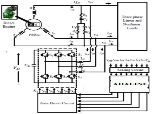
The proposed system comprising of a PMSG based DG set, a three leg VSC, and straight/nonlinear loads, is appeared in Fig. 1. A RC channel is utilized for separating high frequency swell from voltage at PCC (Point of Common Coupling). A 3-leg VSC is utilized a STATCOM. The VSC is connected with PCC through three interfacing inductors. The interfacing inductors connected between three legs of VSC and PCC are utilized to channel the high frequency swells from current. The proposed system utilizes an extraordinarily outlined PMSM of 3.7 kW, 50 Hz, 4-post, 230 V.
III. CONTROL ALGORITHM
Fig.2 exhibits an Adaline based control calculation utilized as a part of the proposed system for estimation of reference source streams. The Adaline based control calculation gauges amplitude of basic parts of active and reactive parts of load streams. It utilizes a settled stride estimate which may have any an incentive from 0.1 to 1 for quick merging. In phase furthermore, quadrature stage unit formats are utilized for estimation of reference source currents.
Fig. 1 Configuration of PMSG based DG set feeding three phase loads.
A. Extraction of Quadrature Phase and In-Phase Unit Templates
In-phase unit templates are extracted by dividing instantaneous phase-voltages by amplitude of phase voltages (Vt) as,
uap = vsa/Vt , ubp = vsb/Vt,, ucp = vsc/Vt (1)
ISSN (Print) : 2320 – 3765 ISSN (Online): 2278 – 8875
I
nternational
J
ournal of
A
dvanced
R
esearch in
E
lectrical,
E
lectronics and
I
nstrumentation
E
ngineering
(A High Impact Factor & UGC Approved Journal)
Website: www.ijareeie.com
Vol. 6, Issue 9, September 2017
=1
3
2 1
−1 1 −1 −2
(2)
The amplitude of phase voltages is obtained from instantaneous phase voltages as [19],
= 2
3( + + ) (3)
The quadrature unit templates are extracted using in-phase unit templates as,
uaq=(- ubq+ ucq )/√3 (4)
ubq=(3uaq+ ubq -ucq )/2√3 (5)
ucq=(3uap+ ubp -ucp)/2√3 (6)
B. Estimation of Active Power Component of Reference Source Current
The Adaline limits the mistake between real load current and its evaluated weight by improving the weights of dynamic
and reactive parts of load streams. The weight vector for dynamic part of load current of each stage is communicated as
[22]
W (n) = W (n−1) +μ*{i (n)−{W (n) × u (n)}}*u (n) (7)
Where, μ is fixed step size having any value from 0.1 to 1. Here the step size in proposed system is taken to be 0.2.
For a three phase system, the weight of active component of load current is given as,
( ) = ( ) + ( ) + ( )
3 (8)
where Wap(n), Wbp(n) and Wcp(n) are weights corresponding to active components of load currents in phase ‘a’, phase
‘b’ and phase ‘c’ respectively.
The weight of active power component of reference source current is obtained by adding weight vectors of (8)
to the weight obtained from the output of DC link voltage PI (Proportional-Integral) controller. The input to DC link PI
controller is an error voltage given as,
Vdcr(n)=Vdcref(n)-Vdc(n) (9)
Where, Vdc(n) is sensed voltage on DC link voltage and Vdcref(n) is reference voltage of the DC link.
The output of the PI controller of DC link can be given as,
WqSTAT(n)=WqSTAT(n-1)+kpdc{Vdcer(n)–Vdcer(n–1)}+kidcVdcer (n) (10)
Where, kpdcand kidcare proportional and integral gain parameters of the PI controller of DC link.
The final estimated weight of the amplitude of active power component of reference source current is given as,
WpT (n)=WqSTAT(n-1)+ Wp (n) (11)
The instantaneous active components of 3-phase reference source currents are obtained by multiplying weight vector of
active power component and in-phase unit templates as under,
∗ ( ) =
ISSN (Print) : 2320 – 3765 ISSN (Online): 2278 – 8875
I
nternational
J
ournal of
A
dvanced
R
esearch in
E
lectrical,
E
lectronics and
I
nstrumentation
E
ngineering
(A High Impact Factor & UGC Approved Journal)
Website: www.ijareeie.com
Vol. 6, Issue 9, September 2017
∗ ( ) =
pT( )∗ ( ) (13)
∗ ( ) =
pT( )∗ ( ) (14)
C. Estimation of Reactive Power Component of Reference Source Current
The weight vector for reactive power component of load current of each phase is given as,
( ) = ( −1) +µ*{ ( )− ( ) × ( ) }* ( ) (15)
Final weight of reactive component of load current is given as,
( ) = ( ) + ( ) + ( )
3 (16)
where Waq(n), Wbq(n) and Wcq(n) are weights corresponding to the reactive components of load currents in phase ‘a’,
phase ‘b’ and phase ‘c’ respectively.
The output of terminal voltage PI controller is considered weight of receptive power part of STATCOM
current. The yield of the terminal voltage PI controller is given as,
WqSTAT(n)=WqSTAT(n-1)+kpv{Ve(n)–Ve(n–1)}+kivVe(n) (17)
where, kpvand kivare gain parameters of terminal voltage PI controller and Ve(n) is error voltage. The error voltage is
computed as,
Ve(n) = Vtref(n) – Vt(n) (18)
Where, Vtref(n) is amplitude of reference terminal phase voltage and Vt(n) is the amplitude of instantaneous phase
voltage at PCC.
The weight of reactive segment of load current is subtracted from the output of terminal voltage PI controller to get the weight vector of reference source current as,
WqT (n) =WqSTAT(n-1)+ Wq (n) (19)
The instantaneous reactive components of three phase reference source currents are obtained weight of reference source current and quadrature phase unit templates as,
i∗ (n) = W
qT(n)∗u (n) (20)
i∗ (n) = W
qT(n)∗u (n) (21)
i∗ (n) = W
qT(n)∗u (n) (22)
D. Estimation of Reference Source Currents
The instantaneous reference source currents are acquired by including instantaneous active and reactive power parts of reference source currents as under,
∗ = ∗ + ∗ ; ∗ = ∗ + ∗ ; ∗ = ∗ + ∗ (23)
ISSN (Print) : 2320 – 3765 ISSN (Online): 2278 – 8875
I
nternational
J
ournal of
A
dvanced
R
esearch in
E
lectrical,
E
lectronics and
I
nstrumentation
E
ngineering
(A High Impact Factor & UGC Approved Journal)
Website: www.ijareeie.com
Vol. 6, Issue 9, September 2017
Fig.2 Adaline based control algorithm for PMSG Based DG set feeding three-phase loads
IV.FUZZY LOGIC CONTROLLER
Fuzzy rationale is a type of numerous esteemed rationales in which reality estimations of variables might be any genuine number somewhere around 0 and 1. By differentiation, in Boolean rationale, reality estimations of variables may just be 0 or 1. Fuzzy rationale has been stretched out to handle the idea of halfway truth, where reality quality may extend between totally genuine and totally false. Besides, when etymological variables are utilized, these degrees might be overseen by particular capacities.
Normally fuzzy rationale control system is made from four noteworthy components exhibited on Figure fuzzification interface, fuzzy induction motor, fluffy principle grid and defuzzification interface. Every part alongside fundamental fuzzy rationale operations will be depicted in more detail below.
1. The selection of appropriate inputs and their fuzzification. 2. The definition of the input and output membership functions. 3. The definition of the Fuzzy Rule Base.
4. The defuzzification of the output obtained after the processing of the linguistic variables with the help of a proper defuzzification technique.
ISSN (Print) : 2320 – 3765 ISSN (Online): 2278 – 8875
I
nternational
J
ournal of
A
dvanced
R
esearch in
E
lectrical,
E
lectronics and
I
nstrumentation
E
ngineering
(A High Impact Factor & UGC Approved Journal)
Website: www.ijareeie.com
Vol. 6, Issue 9, September 2017
Fig4. Control block diagram of fuzzy logic controller
V. SIMULATION RESULTS AND DISCUSSIONS
Performance of the system is analyzed under linear and nonlinear loads at steady state and transient conditions. Linear load is a simple RL type load. The nonlinear load is realized by using a three phase rectifier with a resistance on DC link. An inductor is also connected in series with resistance to inject harmonics in current on ac input. The performance at linear and nonlinear loads is also given here.
Simulation results using pi controller:
(a)
ISSN (Print) : 2320 – 3765 ISSN (Online): 2278 – 8875
I
nternational
J
ournal of
A
dvanced
R
esearch in
E
lectrical,
E
lectronics and
I
nstrumentation
E
ngineering
(A High Impact Factor & UGC Approved Journal)
Website: www.ijareeie.com
Vol. 6, Issue 9, September 2017
(c)
Fig3. Performance under balanced linear loads (a) vsaband isabc(b) vsaband iLabc(c) vsaband icabc
(a)
(b)
ISSN (Print) : 2320 – 3765 ISSN (Online): 2278 – 8875
I
nternational
J
ournal of
A
dvanced
R
esearch in
E
lectrical,
E
lectronics and
I
nstrumentation
E
ngineering
(A High Impact Factor & UGC Approved Journal)
Website: www.ijareeie.com
Vol. 6, Issue 9, September 2017
(d)
Fig4. Dynamic performance at linear loads (a) vsab, isa,isband isc ,(b) vsab, iLa,iLband iLc(c) Vdc, isa,iLaand iCa (d)Vd
(a)
(b)
ISSN (Print) : 2320 – 3765 ISSN (Online): 2278 – 8875
I
nternational
J
ournal of
A
dvanced
R
esearch in
E
lectrical,
E
lectronics and
I
nstrumentation
E
ngineering
(A High Impact Factor & UGC Approved Journal)
Website: www.ijareeie.com
Vol. 6, Issue 9, September 2017
(e)
(f)
(g)
ISSN (Print) : 2320 – 3765 ISSN (Online): 2278 – 8875
I
nternational
J
ournal of
A
dvanced
R
esearch in
E
lectrical,
E
lectronics and
I
nstrumentation
E
ngineering
(A High Impact Factor & UGC Approved Journal)
Website: www.ijareeie.com
Vol. 6, Issue 9, September 2017
Simulation results of fuzzy logic controller:
(a)
(b)
(c)
Fig.3. Performance under balanced linear loads (a) vsaband isabc(b) vsab and iLabc(c) vsab and icabc
ISSN (Print) : 2320 – 3765 ISSN (Online): 2278 – 8875
I
nternational
J
ournal of
A
dvanced
R
esearch in
E
lectrical,
E
lectronics and
I
nstrumentation
E
ngineering
(A High Impact Factor & UGC Approved Journal)
Website: www.ijareeie.com
Vol. 6, Issue 9, September 2017
(b)
(c)
(d)
Fig.4. Dynamic performance at linear loads (a) vsab, isa,isband isc ,(b) vsab, iLa,iLband iLc(c) Vdc, isa,iLaand iCa (d)Vd
ISSN (Print) : 2320 – 3765 ISSN (Online): 2278 – 8875
I
nternational
J
ournal of
A
dvanced
R
esearch in
E
lectrical,
E
lectronics and
I
nstrumentation
E
ngineering
(A High Impact Factor & UGC Approved Journal)
Website: www.ijareeie.com
Vol. 6, Issue 9, September 2017
(b)
(c)
(d)
ISSN (Print) : 2320 – 3765 ISSN (Online): 2278 – 8875
I
nternational
J
ournal of
A
dvanced
R
esearch in
E
lectrical,
E
lectronics and
I
nstrumentation
E
ngineering
(A High Impact Factor & UGC Approved Journal)
Website: www.ijareeie.com
Vol. 6, Issue 9, September 2017
(f)
Fig5. Performance under balanced nonlinear loads (a) vsab and isabc (b) vsab and ilabc (c) vsab and icabc (d) THD of vsab (e)
THD of isa(f) THD of iLa
VI. CONCLUSIONS
STATCOM has been used to power quality improvement of the PMSG based DG set for voltage control, harmonic elimination, and load adjusting. It has also been found that the STATCOM maintains the balanced source currents when the load is highly unbalanced due to removal of load from phase 'c'. The load balancing has additionally been accomplished by proposed system with reduced weight on the winding of the generator. The proposed system is a constant speed DG set so there is no provision of frequency control in the control algorithm.
Under nonlinear loads, the load current of DG set is a quasi square with a THD of 10.47 %. The STATCOM has been found capable to eliminate these harmonics and thus the THD of source currents has been limited to 0.50 % and the THD of terminal voltage has been observed of the order of 0.13%. This is possible with the Fuzzy controller. Therefore, the THDs of source voltage and currents have been maintained well within limits of IEEE-519 standard under nonlinear load.
Therefore, the proposed PMSG based DG set along with STATCOM can be used for feeding linear and nonlinear balanced and unbalanced loads. The proposed PMSG based DG set has also inherent advantages of low maintenance, high efficiency and rugged construction over a conventional wound field synchronous generator based DG set.
Hence, ADALINE based fuzzy controller has given the better results compared to PI controller.
REFERENCES
[1] Xibo Yuan; Fei Wang; Boroyevich, D.; Yongdong Li; Burgos, R., "DC-link Voltage Control of a Full Power Converter for Wind
Generator Operating in Weak-Grid Systems," IEEE Transactions on Power Electronics, vol.24, no.9, pp.2178-2192, Sept. 2009.
[2] Li Shuhui, T.A. Haskew, R. P. Swatloski and W. Gathings, "Optimal and Direct-Current Vector Control of Direct-Driven PMSG Wind Turbines,"
IEEE Trans. Power Electronics, vol.27, no.5, pp.2325-2337, May 2012.
[3] M. Singh and A. Chandra, "Application of Adaptive Network-Based Fuzzy Inference System for Sensorless Control of PMSG-Based Wind
Turbine With Nonlinear-Load-Compensation Capabilities," IEEE Trans. Power Electronics, vol.26, no.1, pp.165-175, Jan. 2011.
[4] A. Rajaei, M. Mohamadian and A. Yazdian Varjani, "Vienna-Rectifier-Based Direct Torque Control of PMSG for Wind Energy Application,"
IEEE Trans. Industrial Elect., vol.60, no.7, pp.2919-2929, July 2013.
[5] Mihai Comanescu, A. Keyhani and Dai Min, "Design and analysis of 42-V permanent-magnet generator for automotive applications," IEEE
Trans. Energy Conversion, vol.18, no.1, pp.107-112, Mar 2003.
[6] S. Javadi and M. Mirsalim, "Design and Analysis of 42-V Coreless Axial-Flux Permanent-Magnet Generators for Automotive Applications,"
IEEE Trans. Magnetics, vol.46, no.4, pp.1015-1023, April 2010
[7] F. Crescimbini, A. Lidozzi and L. Solero , "High-Speed Generator and Multilevel Converter for Energy Recovery in Automotive Systems," IEEE
Trans. Industrial Elect., vol.59, no.6, pp.2678-2688, June 2012
ISSN (Print) : 2320 – 3765 ISSN (Online): 2278 – 8875
I
nternational
J
ournal of
A
dvanced
R
esearch in
E
lectrical,
E
lectronics and
I
nstrumentation
E
ngineering
(A High Impact Factor & UGC Approved Journal)
Website: www.ijareeie.com
Vol. 6, Issue 9, September 2017
[9] A. D. Hansen and G. Michalke, "Multi-pole permanent magnet synchronous generator wind turbines' grid support capability in uninterrupted operation during grid faults," IET Renewable Pow er Generation, vol.3, no.3, pp.333-348, Sept. 2009.
[10] Bhim Singh and Ram Niwas” Power Quality Improvement of PMSG Based DG Set
Feeding Three-Phase Loads“IEEE Transactions on Industry Applications”
[11] T. F. Chan, LL. Lai and Yan Lie-Tong, "Performance of a three-phase AC generator with inset NdFeB permanent-magnet rotor," IEEE Trans.
Energy Conversion, vol.19, no.1, pp.88-94, March 2004.
[12] Z. Chen, E. Spooner, W. T. Norris and A. C. Williamson, "Capacitor-assisted excitation of permanent-magnet generators," IEE Proc. Electric
Power Applications, vol.145, no.6, pp.497-508, Nov 1998.
[13] M.A. Rahman, A. M. Osheiba, T.S. Radwan and E.S. Abdin, "Modelling and controller design of an isolated diesel engine permanent magnet
synchronous generator," IEEE Trans. Energy Conversion, vol.11, no.2, pp.324-330, Jun 1996.
[14] Y. Errami, M. Maaroufi and M. Ouassaid, “Variable Structure Direct Torque Control and grid connected for wind energy conversion system
based on the PMSG,” International Conference on Complex Systems (ICCS), 2012, pp.1-6, 5-6 Nov. 2012.
[15] B. Singh and J. Solanki, "Load Compensation for Diesel Generator-Based Isolated Generation System Employing DSTATCOM," IEEE Trans.
Industry Applications, vol.47, no.1, pp.238-244, Jan.-Feb. 2011.
[16] P. Mitra and G.K. Venayagamoorthy, "An Adaptive Control Strategy for DSTATCOM Applications in an Electric Ship Power System," IEEE
Trans. Power Electronics, vol.25, no.1, pp.95-104, Jan. 2010.
[17] A. Ghosh and G. Ledwich, "Load compensating DSTATCOM in weak AC systems," IEEE Trans. Power Delivery, vol.18, no.4, pp.1302-1309,
Oct. 2003
[18] B. Singh and S.R. Arya, "Adaptive Theory-Based Improved Linear Sinusoidal Tracer Control Algorithm for DSTATCOM," IEEE Trans. Power
Electronics, vol.28, no.8, pp.3768-3778, Aug. 2013.
[19] B. Singh and S. Sharma, “Stand-Alone Single-Phase Power Generation Employing a Three-Phase Isolated Asynchronous Generator,” IEEE
Trans. Industry Applns., vol.48, no.6, pp.2414-2423, Nov.-Dec. 2012.
[20] B. Singh, V. Sheeja, R. Uma and P. Jayaprakash, “Voltage- frequency controller for standalone WECS employing permanent magnet
synchronous generator,” International Conference on Power Systems, 2009. ICPS '09, pp.1-6, 27-29 Dec. 2009.
[21] B. Singh, S.R. Arya, A. Chandra and K. Al-Haddad, “Implementation of adaptive filter based control algorithm for Distribution Static
Compensator,” Annual Meeting Industry Applications Society (IAS), 2012 IEEE, pp.1-8, 7-11 Oct. 2012.
[22] B. Singh and J. Solanki, “A comparison of control algorithms for DSTATCOM,"IEEE Trans. Ind. Elect., vol.56, no.7, pp.2738-2745, July