Performance Analysis of Fiber Optical
Communication using Fiber Bragg Grating as
Dispersion Compensator
Bibhu Prasad 1, Dr. K. C. Patra2, Dr. N.K Barpanda3
Research Scholar, SUIIT Sambalpur , odisha, India1
Professor, Department of Electronics, SUIIT, Sambalpur, odisha, India2
Professor, Department of Electronics, GIET, Gunupur, Odisha, India 3
ABSTRACT: With the increasing growth and demand for capacity in national, regional, and even metropolitan optical
networks, high bit rate fiber transmission has recently become an essential part of communications. The high bit rate transmission improves spectral utilization which results in increased overall system capacity and reduces overall cost. The optical communication systems are used as high speed long–haul communication systems. Although optical fiber communication has a lot of advantages, dispersion is the main performance limiting factor. There are various types of optical fiber compensators, but Fiber Bragg Grating (FBG) is commonly chosen as important components to compensate the dispersion in optical communication system. FBG is very simple, has low cost filter for wavelength selection and low insertion loss, it has also customized reflection spectrum and wide bandwidth. We have analyzed the dispersion compensation using Fiber Bragg Grating at different fiber lengths and at different value of input power and fbg length. The simulated transmission system have been analyzed on the basic of different parameters which include input power (dBm), fiber cable length (km), FBG Length (mm) by using OptiSystem 7 .
KEYWORDS:fiber Optical Transmission System, Fiber Bragg Grating (FBG), dispersion compensation, EYE
DIAGRAM, Q-factor, Optisystem7
I.INTRODUCTION
In fiber optic communication is transmitted pulses of light through an optical fiber, where the light forms an electromagnetic carrier wave that is modulated to transport information. This way the fiber optic is the medium, and the light pulses the message. Fiber optics is a medium for carrying information from one point to another in the form of light. Unlike, the copper form of transmission, fiber optics is not electrical in nature. A basic fiber optic system consists of a transmitting device that converts an electrical signal into a light signal, an optical fiber cable that carries the light, and a receiver that accepts the light signal and converts it back into an electrical signal .Fiber Bragg gratings (FBGs) have been widely applied in optical Sensors and optical communications due to the promising Performances with electro-magnetic immunity, compactness, Remote sensing, ease of fabrication and wavelength selectivity[1].
Optisystem is an innovative optical communication system simulation package that designs tests and optimizes virtually any type of optical link in the physical layer of a broad spectrum of optical networks, from analog video broadcasting systems to intercontinental backbones. It is a system level simulator based on the realistic modelling of fiber-optic communication systems.
In this study, the simulation of the optical system in optical fiber has been discussed by analyzing the effect of the components by using different parameters setting. The value of parameters has been investigated such as Signal power (dBm), output power (dbm),Q-Factor
II.SYSTEM MODEL
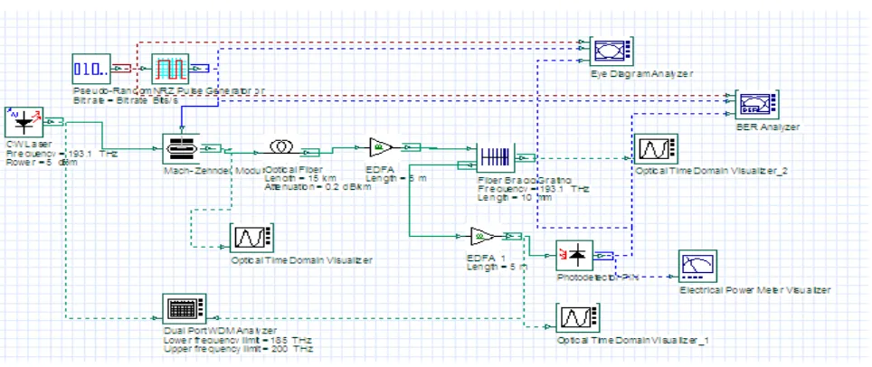
single mode (SMF) because it has less distortion occur. The simulation is taken by putting the FBG in the path of optical fiber .FBG is so chosen which has step size of 5 mm. the following parameters are so select for simulation.
TABLE 1: SIMULATION PARAMETERS
C/W LASER POWER 15 dBm C/W LASER FREQ 193.1THz REFERENCE WAVELENGTH 1550nm
FIBER LENGTH 15km ATTENUATION 0.2db/km
EDFA LENGTH 5km
FBG Length
5mm2.1Simulation model of a transmission system
Fig 1: Designed simulation model using Optisystem7
III.RESULTS AND ANALYSIS
Fig 2. Eye diagrams Simulation of a transmission system of analyzed
5km 10km
Fig 3 .Eye diagrams are analyzed using different values of OFC length at input power 0dBm
25km 30km
Fig 4 .Eye diagrams are analyzed using different values of fiber length at input power 5dBm
1mm 2mm 5mm 10mm
Fig 5. Eye diagrams are analyzedat different values of fiberbragg grating
Table 2: output readings are tabulated by varying the OFC Length (km)
OFC LENGTH(KM)
OUTPUT POWER(dBm)
Q-FACTOR (dB)
10 12.134 48.2326 15 12.094 48.2096 20 12.061 30.1123 25 12.035 23.2063 30 12.009 13.9371
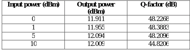
Table 3: output readings are tabulated at different input power
Input power (dBm) Output power
(dBm)
Q-factor (dB)
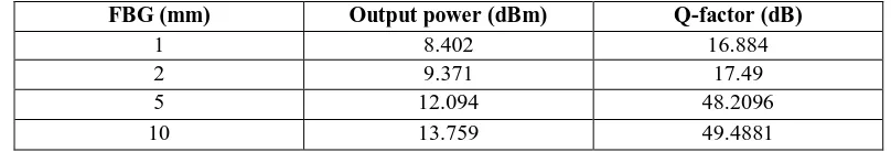
Table 4 : output readings are tabulated at different value of fiber Bragg gratings
FBG (mm) Output power (dBm) Q-factor (dB)
1 8.402 16.884
2 9.371 17.49
5 12.094 48.2096
10 13.759 49.4881
IV.CONCLUSION
We have analyzed the dispersion compensation using Fiber Bragg Grating at different fiber lengths and at different fbg. The simulated transmission system has been analyzed on the basic of different parameters. The optical transmission system has been modelled by using Optisystem7.0 simulator as shown in Figure 5 in order to investigate different parameters of the system. From the simulation result, it can conclude that the fiber Bragg grating length and the input power are directly proportional to the signal power. . When input power (dBm) is increased then its output power (dbm), is increased but Factor (db) is decreased . FBG Length (db) is increased then output power (dbm) and Q-Factor(db) are increased.
REFERENCES
[1] B.Prasad1 B.Mallick2 A.K.Parida3“Fiber Bragg Grating as a Dispersion Compensator in an Optical Transmission System Using
Optisystem Software” in , International Research Journal of Engineering and Technology (IRJET) , Volume: 02 Issue: 06 | Sep -2015
[2] S. O. Mohammadi,SaeedMozzaffari and M. Mahdi Shahidi, (2011). “Simulation of a transmission system to compensate dispersion in an
optical fiber by chirp gratings.” International Journal of the Physical Sciences, Vol. 6(32), pp. 7354 - 7360, 2 December.
[3] Anandita joy agarwal1 ,Mukeshkumar 2 , A.K Jaiswal 3 , RohiniSaxena“Analysis to Compensate Dispersion in Optical Communication
Link Using Chirp Grating”International Journal of Electronics and Computer Science Engineering(IJECSE),Volume2, Number 3,pg 980-986.
[4] Gopika P1 , Sunu Ann Thomas “Performance Analysis of Dispersion Compensation using FBG and DCF in WDM Systems”
International Journal of Advanced Research in Computer and Communication Engineering Vol. 4, Issue 10, October 2015.
[5] Nidhiya Shan, Asha A S, ”Simulation and Analysis of Optical WDM System Using FBG as Dispersion Compensator, ”International
Journal of Engineering Research and General Science, Volume 3,Issue 2,March-April 2015.
[6] Navneet Singh Aulakh, " Investigations on fiber bragg gratings for fiber optic communication systems” department of electronics
&communication engineering thapar university 2010.