421 | P a g e
Design and Analysis of Flywheel by Using Finite Element
Analysis
Madhusudhan Reddy K
1, Suneel Kumar B
2PG Scholar, Department of Mechanical Engineering,
Visvodaya Institute of Technology and Science, Kavali, SPSR Nellore(Dt), A.P, India.
Assistant Professor, Department of Mechanical Engineering,
Visvodaya Institute of Technology and Science, Kavali, SPSR Nellore(Dt),A.P, India.
ABSTRACT
A Flywheel is used in machines which is used to stores energy and energy is more than the requirement releases
the requirement of energy is more than supply. A Flywheel is located on one end of the crankshaft and its inertia
it reduces the vibration which outs the power stroke in each cylinder fires. The Flywheel is designed in 3D
modelling CATIA. The analysis of the will be done by the prototype of Flywheel is done by using Cast Iron and
aluminium alloy A360. The comparison can be done with the materials and the best material after the analysis
is Flywheel aluminium alloy A360.
Index Terms – Flywheel, CATIA, Alloy.
I.INTRODUCTION
Modern technology has enabled a new application for the age old flywheel in advanced flywheel energy storage
systems. Flywheel energy storage systems store kinetic energy in the form of a rotating flywheel typically made
of composite materials. These systems are often called mechanical batteries since electrical energy is input,
stored as rotational mechanical energy, and converted back to electrical energy to provide power on demand.
NASA Glenn Research Centre (NASA-GRC) expressed a need for a means to monitor the health of a composite
flywheel constructed of concentric preloaded composite rings. In response, the University of Texas Centre for
Electromagnetic (UTCEM) designed a flywheel that exhibits a change in mass.
Eccentricity when fatigue, thermal expansion, or other phenomena cause a loss in preload of the outer
ring. The design is such that the outer ring of the flywheel is only bonded to next inner ring on 180degrees of the
contact area. As a result, centripetal acceleration causes the outer ring to grow asymmetrically if the preload is
lost. The existence of preload or compression between the rings is important since it provides the structural
integrity of the flywheel. The outer ring preloadis designed to be maintained to just above maximum operating
speed. Therefore, the asymmetric growth would only be sensed in the operating speed range if the preload was
422 | P a g e
material causes a reductionin the ring hoop stiffness which in turn reduces the preload. Texas A&M Vibrationand Controls laboratory has been sponsored by NASAGRC to utilize a magnetic suspension system to develop
health monitoring techniques utilizing the UT-CEM Preload Loss Monitor technology.
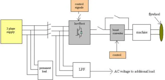
Figure. 1 Block Diagram of The Flywheel Energy Storage System (FESS)
1.1. Product
Figure. 2 Flywheel Absorption Edges and Charging Mechanism
The flywheel is charged using the principle of the Crookes Radiometer. The glass flywheel structure
therefore is very important. Two materials properties of the glass are manipulated to allow charging. The
refractive index and colorof the glass are used to control the absorption at the surface of the glass. Similar to the
Crookes radiometer the glass flywheel has alternating faces that absorb different amounts of radiation. This is
schematically shown in Figure 2 by black and white fringes at the surface of the flywheel.
1.2. Flywheel Concept
There are many ways that energy can be stored; in chemical bonds (fuel), in the energy to separate ions
423 | P a g e
flywheel, the inertia of a rotating mass is used to store energy. The potter’s wheel is a low-tech example of this from antiquity. In a potter’s wheel, the potter spins the wheel up from a stop by kicking it with her feet. Thenwhen the potter moulds the clay with her hands, she kicks the wheel occasionally to maintain the speed of
rotation against the frictional forces that sap its energy and slow it down. Some of the friction is in the bearings
of the wheel, and some is from working the clay. The purpose of the wheel is to keep the clay moving in a
circular path so that it can be shaped into a vessel of cylindrical symmetry. The operation of a modern flywheel
is somewhat like the heating system in your house, when operating under the control of a thermostat.
It is sped up to its idling speed, it very slowlyloses speed over some period of time, and then it is sped
up to idling speed again. In the metaphorical comparison to home, heating, your furnace brings the house up to
the set temperature, the furnace turns off, the house slowly cool sowing to the losses of heat through the walls,
windows, and ceiling, and when the lower bound of the acceptable temperature range is reached, the furnace
turns back on to raise the temperature to the top of the band again.
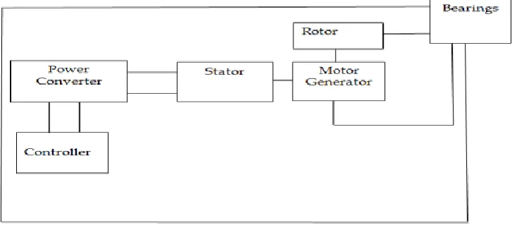
Figure. 3 Flywheel Subsystems
II. LITERATURE SURVEY
Today’s industries cannot survive worldwide competition unless they introduce new products with better quality
(quality, Q), at lower cost (cost, C), and with shorter lead time (delivery, D). Accordingly, they have tried to use
the computer’s huge memory capacity, fast processing speed, and user-friendly interactive graphics capabilities
to automate and tie together otherwise cumbersome and separate engineering or productionthus reducing the
time and cost of product development and production. Computer-aided design (CAD), computer-aided
manufacturing (CAM), and computer-aided engineering (CAE) are the technologies used for this purpose during
the product cycle. Thus, to understand the role of CAD, CAM, and CAB, we need to examine the various
activities and functions that must be accomplished in the design and manufacture of a product. These activities
and functions are referred to as the product cycle. The product cycle described by Zeid is presented here with
424 | P a g e
2.1. Definitions of CAD, CAM, AND CAEAs described in the previous section, computer-aided design (CAD) is the technology concerned with
the use of computer systems to assist in the creation, modification, analysis, and optimization of a design [
Grover and Zimmer’s 1984]. Thus any computer program that embodies computer graphics and an application
program facilitating engineering functions in the design process is classified as CAD software. In other words,
CAD tools can vary from geometric tools for manipulating shapes at one extreme, to customized application
programs, such as those for analysis and optimization, at the other extreme [Zeid 1991].
Between these two extremes, typical tools currently available include tolerance analysis, mass property
calculations, and finite-element modelling and visualization of the analysis results, to name a few. Process
planning is also a target of computer automation; the process plan may determine the detailed sequence of
production steps required to fabricate an assembly from start to finish as it moves from workstation to
workstation on the shop floor.
Even though completely automatic process planning is almost impossible, as mentioned previously, a
process plan for a part can be generated if the process plans for similar parts already exist. For this purpose,
group technology has been developed to organize similar parts into a family. Parts are classified as similar if
they have common manufacturing features such as slots, pockets, chamfers, holes, and so on. Therefore, to
automatically detect similarity among parts, the CAD database must contain information about such features.
This task is accomplished by using feature-based modelling or feature recognition.
III. MODELLING OF FLYWHEEL
3.1. CATIA
CATIA (Computer Aided Threedimensional Interactive Application) is a multiple form
CAD/CAM/CAE commercial software suite developed by French company Dassault systems. The software was
created in late 1970s to develop Dassault’s Mirage fighter jet, but wassubsequently adapted in aerospace,
automotive ship building, and other industries.
3.2. History
CATIA started as in-house development by French aircraft manufacturer Avion Marcel Dassault’s. The
software name was initially CATI (Conception AssisteeTridimensionelle Interactive- French for Interactive
aided three dimensional Designs), but was renamed CATIA in 1981. In 1990, General Dynamics/Electric Boat
Corp chose CATIA as its main 3D CAD tool, to design the United States Navy Virginia Class Nuclear
Submarine. In 1992 CADAM was purchased from IBM .In 1996 CATIA V4 was ported from one to four UNIX
operating systems. In 1998, an entirely rewritten version of CATIA V5 was released with support for UNIX,
425 | P a g e
3.3. Where is CATIA Used?CATIA is being used by designers, manufacturing facilities, assemblers, architects, industrial engineers
etc. Have a Look around you. Everything and Anything you see had to be designed before manufacturing. The
desk you are using, the chair you are sitting in, your daily use appliances, your car, your home etc. The list is
almost endless. Nearly everything is being designed on computers. CATIA plays a major role in the design
process. CATIA is being used by the majority of automotive and aerospace industries for automobile and
aircraft products and its auxiliaries and tooling design. Thousands of engineering companies throughout the
world over are using CATIA. A Company using CATIA has suppliers using CATIA too, thus making CATIA
an Essential tool.
As mentioned earlier, CATIA V5 has different workbenches such as the Part Design workbench,
Assemble design workbench, and drawing workbench. The bidirectional associative that exists between all these
workbenches ensured that any modify the dimension of a part in the part in the part design workbench; the
change will be reflected in the assembly design and the drawing workbenches. Similarly, if you modify the
dimensions of a part in the drawing views generated in the Drawing workbench, the changes will be reflected in
the part design Assembly design workbenches.
3.4. File Extensions for CATIA
CAT Part:
CAT Part is a file extension associated with at the files that are created in the sketcher. Part Design and
wireframe and surface design workbenches of CATIA V5.
CAT Drawing:
Cat Product is a file extension associated with all the files that are created in the assembly design workbench of
427 | P a g e
IV. PRE AND POST PROCESSING OF FLYWHEEL
Ansys is the standard FEA teaching tool within the engineering department at many colleges. Ansys is also used
in civil and Electrical engineering, as well as physics and chemistry department. Ansys provide a cost effective
way to explore the performance of the products and processes in a virtual environment. This type of product
development is termed as virtual Prototyping. With virtual prototyping techniques users can iterate various
scenarios to optimize the product long before manufacturing is started.
This enables a reduction in level of risk, And in the cost of ineffective designs. The multifaceted nature of Ansys
also provides a means of ensure that users are able to see the effect of designs on the whole behaviour of the
product, be it electromagnetic, thermal, mechanical etc.
4.1. Generic Steps to Solving Any Problem in Ansys
Like solving any problem analytically you need to define (1) your solution domain, (2) the physical
model, (3) boundary conditions and (4) the physical properties. You then solve the problem and present the
results. In numerical methods, the main difference in an extra step called mesh generation. This is the step that
divides the complex model in to small elements that become soluble in an otherwise too complex situation.
Below describes the process in terminology. Slightly more attune too the software.
Build Geometry - Construct a 2 or 3 –D representation of the object to be modelled and tested using the work
plane coordinates system in Ansys.
Define Material Properties - Now that the part exists, define a library of necessary materials that composed an
428 | P a g e
Generate Mesh - At this point Ansys understands the makeup of the part. Now define how the model systemshould be broken down into finite pieces.
Apply Loads - Once the system is fully designed, the last task is to burden the system with constraints, such as
physical loadings or boundary conditions.
Obtain Solution - This is actually a step because Ansys need to understand within what state (steady state,
transient… etc.) The problem must be solved.
Present the Results - After the solution has been obtained there are many ways to present Ansys results,
Choose from many options such as tables, graphs and contour lots.
4.2. Specific Capabilities of Ansys
4.2.1.Structural
Structural analysis is probably the most common application of the finite element method is as it
implies bridges and buildings, naval, aeronautical and mechanical structure such as ship halls, air craft’s and
machines housing as well as mechanical components such as pistons, machine parts and tools. Static analysis
issued to determine displacement; stresses etc. under static loading conditions ANSYS can compute both linear
and non-linear static analysis. Non linearity can include plasticity, stress stiffening, large deflection, large strain,
hyper elasticity, contact surface and creep.
4.2.2. Transient Dynamic Analysis
Used to determine the response of structural to arbitrary time varying loads. All non-linearity’s
mentioned under static analysis above are allowed.
4.2.3. Buckling Analysis
Issued to calculate the buckling loads and determine the buckling mode shape. Both linear and
non-linear buckling analysis is possible.
In addition to the above analysis types, several special purpose features are available such as fracture mechanics,
composite material analysis, fatigue and both p-Method and beam analysis.
4.2.4. Thermal
ANSYS is capable of both steady state and transient analysis of any solid with thermal boundaries
condition. Study state thermal analyses calculate the effects of steady thermal loads on a system or component.
User often performs a steady state analysis before doing a transitional thermal analysis to help establish initial
conditions. A steady state analysis also can be the last step of a transient thermal analysis; performed after all
transient effects have diminished. ANSYS can be used to determine temperatures, thermal gradient, heat flow
rate and heat fluxes in an object that are caused by the thermal loads that do not vary over time. Such loads
include the following
429 | P a g e
Radiation Heat flow rate
Heat fluxes (Heat flow per unit area)
Heat generation rates (heat flow per unit volume)
Constant temp. boundaries
The steady state thermal analysis may be either linear, with constant material property, or non-linear
with material properties that depend on temperature. The thermal properties most material varies with
temperature. This temperature dependency being appreciable, the analysis becomes non-linear. Radiation
boundary conditions also make the analysis non-linear. Transient calculations are time dependent and ANSYS
can both solve distributions as well as create videos for time incremental displace of models.
4.3. Coupled Fields
A coupled field analysis is an analysis that takes into account the interaction between two or more
fields of engineering. A peizo electric analysis, for example handles the interaction between the structural and
electric fields: it solves for the voltage distribution due to applied displacement or vice versa. Other examples of
coupled field analysis are thermal stress analysis, thermal electric analysis and fluid structure analysis. Some of
the applications in which coupled field analysis may be required are pressure vessel, fluid structure analysis,
induction heating, ultrasonic transducer, magnetic forming and micro electro mechanical system (MEMS).
4.4. Model Analysis
A model analysis is typically used to determine the vibration characteristic of a structure or a machine
component while it is being designed it can also serve as a starting point of another, more detailed, dynamic
analysis, such as a harmonic respond=se or full transient dynamic analysis.
Model analysis, while being one of the most basic dynamic analysis types available in ANSYS, can also be
more computationally time consuming than a typical static analysis. A reduced solver, utilizing automatically or
manually selectedmaster degrees of freedom is used to drastically reduce the problem size and solution time.
4.5. Harmonic Analysis
Used extensively by companies who produce rotating machinery, ANSYS harmonic analysis is used to
predict the sustained dynamic behavior to consistent cyclic loading. A harmonic analysis can be used to verify
whether or not a machine design will successfully overcome resonance, fatigue and other harmful effects of
430 | P a g e
V. RESULTS AND DISCUSSIONS
Figure. 4 Imported model from CATIA
Element Type : solid 20 nodes 95
Material Properties
Young’s modulus (EX) : 103000N/mm2 Poisson’s ratio (PRXY) : 0.33
Density : 0.0000071Kg/mm3
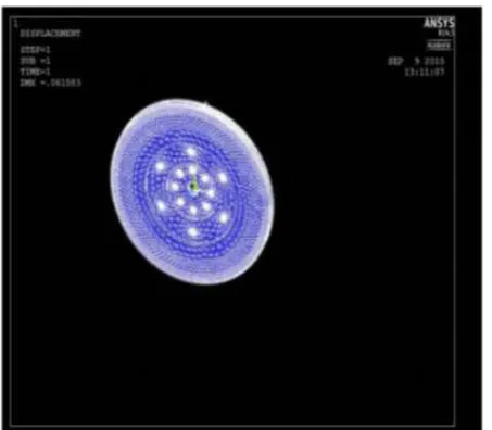
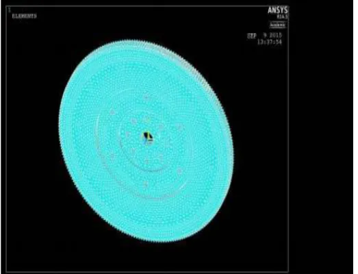
5.1. Meshed Model
Figure 5 Meshed Model
Loads
431 | P a g e
Poisson’s ratio (PRXY): 0.33Density : 0.0000071Kg/mm3
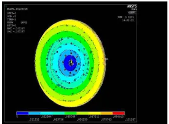
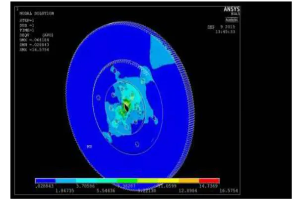
5.2. Post Processor
General Post Processor–Plot Results-Contour Plot-Nodal Solution-DOF Solution-Displacement Vector
Sum.
Figure. 6 Displacement Vector Sum
432 | P a g e
5.3. Structural Analysis of Flywheel using Aluminium alloyA360Imported model from CATIA V5 is drawn in CATIA
Element Type : solid 20 nodes 95
Material Properties
Young’s modulus (EX) : 240000N/mm2 Poisson’s ratio (PRXY : 0.33
Density : 0.0000071Kg/mm3
5.4. Meshed Model
433 | P a g e
5.5. Post ProcessorGeneral Post Processor–Plot Results-Contour Plot-Nodal Solution-DOF Solution-Displacement Vector
Sum.
Figure. 9 Displacement Vector Sum
434 | P a g e
VI. COMPARSION OF RESULTS
CAST IRON:
LOAD STEP=1 SUBSTEP=1
TIME=1.0000
LOAD CASE=0
The following degree of freedom results are in the global coordinate system
NODE UX UY UZ USUM
1 0.20436E-01-0.74158E-01 0.83753E-02 0.77377E-01
2 0.20109E-01-0.76900E-01 0.79079E-02 0.79879E-01
3 0.19448E-01-0.78895E-01 0.77396E-02 0.81624E-01
4 0.18097E-01-0.77680E-01 0.71470E-02 0.80079E-01
5 0.17392E-01-0.79702E-01 0.69378E-02 0.81872E-01
6 0.16042E-01-0.78373E-01 0.64296E-02 0.80256E-01
7 0.15238E-01-0.80512E-01 0.63486E-02 0.82187E-01
8 0.13913E-01-0.79134E-01 0.58981E-02 0.80564E-01
9 0.12760E-01-0.81920E-01 0.59689E-02 0.83122E-01
10 0.10778E-01-0.79677E-01 0.58904E-02 0.80618E-01
11 0.99567E-02-0.81423E-01 0.55286E-02 0.82216E-01
12 0.85597E-02-0.79655E-01 0.51369E-02 0.80278E-01
13 0.78348E-02-0.81132E-01 0.47690E-02 0.81649E-01
14 0.65731E-02-0.79565E-01 0.43323E-02 0.79953E-01
15 0.57834E-02-0.81031E-01 0.39401E-02 0.81333E-01
16 0.45786E-02-0.79463E-01 0.35121E-02 0.79672E-01
17 0.37064E-02-0.80904E-01 0.31561E-02 0.81050E-01
18 0.25622E-02-0.79350E-01 0.27343E-02 0.79438E-01
19 0.16336E-02-0.80759E-01 0.23682E-02 0.80811E-01
20 0.53580E-03-0.79215E-01 0.19682E-02 0.79241E-01
ALUMINIUM ALLOY A360:
LOAD STEP= 1
SUBSTEP=1
TIME=1.0000
LOAD CASE=0
The following degree of freedom results are in the global coordinate system
NODE UX UY UZ USUM
1 0.17167E-02-0.96981E-02 0.83629E-02 0.12921E-01
435 | P a g e
3 0.95640E-03-0.43715E-02 0.77835E-02 0.89781E-024 0.15215E-02-0.83753E-02 0.77644E-02 0.11522E-01
5 0.13344E-02-0.70410E-02 0.77625E-02 0.10565E-01
6 0.11453E-02-0.57194E-02 0.77721E-02 0.97175E-02
7 0.98245E-03-0.42934E-02 0.83807E-02 0.94676E-02
8 0.11670E-02-0.56484E-02 0.83622E-02 0.10158E-01
9 0.13480E-02-0.69978E-02 0.83498E-02 0.10978E-01
10 0.15329E-02-0.83444E-02 0.83512E-02 0.11905E-01
11 0.10619E-02-0.50147E-02 0.80734E-02 0.95632E-02
12 0.16199E-02-0.90303E-02 0.80593E-02 0.12212E-01
13 0.10053E-02-0.42958E-02 0.92335E-02 0.10233E-01
14 0.17508E-02-0.97397E-02 0.92196E-02 0.13525E-01
15 0.11916E-02-0.56566E-02 0.92242E-02 0.10886E-01
16 0.13770E-02-0.70216E-02 0.92172E-02 0.11669E-01
17 0.15634E-02-0.83738E-02 0.92149E-02 0.12549E-01
18 0.16405E-02-0.90412E-02 0.87861E-02 0.12713E-01
19 0.10864E-02-0.49701E-02 0.87982E-02 0.10163E-01
20 0.17554E-02-0.97240E-02 0.97897E-02 0.13910E-01
VII. CONCLUSIONS
This project deals with modelling of a flywheel. A 3D model is designed by using 2D drawings in CATIA and
CAD tool. Structural analysis is done on the flywheel using the materials cast iron and aluminium alloy A360.
By observing the stress values from the results, the values are less than their respective permissible values for
both the materials. So it can be concluded that design is safe. By comparing the displacement and stress values
for both materials, the values are less for aluminium alloy A360 when compared to cast iron. So we can
conclude that as per the analysis done, the best material for flywheel is aluminium alloy A360.
REFERENCES
[1] Theory of Machines – R.S.Khurmi
[2] Theory of Machines – Thomas Beven
[3] Desighn of Machine Members – H.Shingley
[4] Desighn of Machine Members – R.S.Khurmi
[5] Desighn Data – Psg Publications
[6] Autobile Engineering- William Crouse
[7] www.wikipedia.com
[8] www.google.co.in