SCADA SECURITY DEVICE: DESIGN AND IMPLEMENTATION
A Thesis by Aniket Rodrigues
Bachelor of Science, Wichita State University, 2009
Submitted to the Department of Electrical Engineering and Computer Science and the faculty of the Graduate School of
Wichita State University in partial fulfillment of the requirements for the degree of
Master of Science
© Copyright 2011 by Aniket Rodrigues All Rights Reserved
SCADA SECURITY DEVICE: DESIGN AND IMPLEMENTATION
The following faculty members have examined the final copy of this thesis for form and content, and recommend that it be accepted in partial fulfillment of the requirement for the degree of Master of Science, with a major in Electrical Engineering.
______________________________________ Ravi Pendse, Committee Chair
______________________________________ Gamal Weheba, Committee Member
______________________________________ Vinod Namboodiri, Committee Member
DEDICATION
ACKNOWLEDGEMENTS
I would like to thank my advisor, Dr. Ravi Pendse, for his patient guidance at all stages of this thesis. I would especially like to thank Dr. Tish Best for her continued support and help throughout the course of this research. I would also like to extend my gratitude to members of my committee, for their helpful comments and suggestions.
ABSTRACT
Securing SCADA systems is a critical aspect of Smart grid security. As sophisticated attacks continue to target industrial systems, the focus should be on planning and developing new security techniques that will adapt to the SCADA environment and protocols. Traditional SCADA protocols such as DNP3, Modbus and ICCP do not support encryption, authentication and data integrity in their native form. Although they can be secured with VPN tunnels, IPSEC adds significant network overhead and complexity to the end hosts. SCADA devices may lack the computing resources to implement this kind of technique. In this thesis, a security design is proposed that can help make communications between the master stations and slave devices in a SCADA network secure without putting additional overhead on the remote devices. This research designs a SCADA Security Device (SSD), which can work in conjunction with other network elements to implement a secure architecture for SCADA protocols. Several components of the SSD were implemented and tested during this research to evaluate the security features in a SCADA network.
TABLE OF CONTENTS
Chapter Page
1. INTRODUCTION ... 1
1.1 Overview of the Smart Grid ... 1
1.2 Components of the Smart Grid ... 2
1.3 Overview of SCADA ... 3
1.4 Need for Security in Smart Grid ... 5
2. LITERATURE REVIEW ... 7
2.1 Secure Communication Protocols ... 7
2.1.1 Transport Layer Security ... 7
2.1.2 Datagram Transport Layer Security ... 8
2.2 Public Key Infrastructure ... 9
2.2.1 Public and Private keys ... 9
2.2.2 Certificates and Certificate Authority ... 9
2.2.3 Certificate Revocation ... 10
2.3 Attacks on SCADA – Stuxnet ... 10
2.4 SCADA communication protocols ... 13
2.4.1 Distributed Network Protocol 3 ... 13
2.4.2 Modbus TCP ... 15
2.5 Snort IPS ... 16
2.6 Related Work ... 17
3. METHODOLOGY ... 21
3.1 SCADA Security Architecture ... 21
3.2 SCADA Security Device... 22
3.2.1 DoS Protection Engine ... 25
3.2.2 Signature Engine ... 26
3.2.3 State Engine ... 26
3.3 Packet Processing Flowchart ... 28
3.4 Network Management using SNMP ... 31
4. SIMULATION ... 32
4.1 Modbus/TCP Testbed ... 32
4.2 DoS Engine Implementation ... 33
TABLE OF CONTENTS (cont.)
Chapter Page
5. RESULTS ... 37
5.1 Attack Prevention Case 1 ... 37
5.2 Attack Prevention Case 2 ... 37
5.3 Attack Prevention Case 3 ... 39
5.4 Performance Analysis ... 40
6. CONCLUSIONS AND FUTURE WORK ... 42
REFERENCES ... 44
APPENDIX ... 47
LIST OF TABLES
Table Page
3.1 Master Table ... 25 3.2 Slave Table ... 27
LIST OF FIGURES
Figure Page
2.1 DNP3 Packet Format ... 14
2.2 Control Field of DNP3 Packet Header... 14
2.3 Modbus ADU/PDU ... 15
2.4 Modbus MBAP Header ... 16
3.1 SSD Deployed in a SCADA Network ... 23
3.2 TLS Proxy Mechanism of SSD... 24
3.3 Packet Processing Flowchart ... 28
4.1 Modbus Server and Client with SSD Inline ... 32
4.2 Sample Attack Scenario on SCADA Network ... 33
5.1 Alert 1 Generated by Snort Engine ... 37
5.2 Alert 2 Generated by Snort Engine ... 37
5.3 Alert 3 Generated by Snort Engine ... 38
5.4 Alert 4 Generated by Snort Engine ... 38
5.5 Alert 5 Generated by Snort Engine ... 38
LIST OF ABBREVIATIONS / NOMENCLATURE
AMI Advanced Metering Infrastructure CA Certificate Authority
DoS Denial of Service
DDoS Distributed Denial of Service DNP3 Distributed Network Protocol 3 DTLS Datagram Transport Layer Security HMI Human Machine Interface
IED Intelligent Electronic Device IPS Intrusion Prevention System IPSEC IP Security
PLC Programmable Logic Controller RTU Remote Terminal Unit
SCADA Supervisory Control and Data Acquisition SNMP Simple Network Management Protocol SSD SCADA Security Device
SSL Secure Socket Layer
TCP Transmission Control Protocol TLS Transport Layer Security UDP User Datagram Protocol VPN Virtual Private Network
CHAPTER 1 INTRODUCTION
1.1 Overview of the Smart Grid
The power, automation and controls industries in the United States have evolved into sophisticated systems over the past decade. These systems play a very important role in our everyday lives, yet they tend to be easily forgotten. The power grid in the United States has been a very stable system, however, there have been events in the past that prove that these systems are still vulnerable to failures. It is therefore important for all of us to get involved and contribute towards developing systems which are more reliable, secure and technologically advanced to keep up with the fast growing IT world. Smart grid is an initiative that tends to bring together the various isolated power and industrial control systems and build intelligence into them, while they get more exposed to the ever growing Internet domain. These systems have always had intelligence and technology drive them forward, but they have lacked the benefits that interconnected systems such as the Internet have long enjoyed. The Smart grid initiative is commonly attributed to only the power industry; however, it is also responsible for other domains in the automation and controls sector. These domains are categorized into operations, transmission, distribution, service provider and customer.
Key benefits of the Smart grid are outlined in this section. The Smart grid [1] will enable bidirectional flow of energy, which would be an effective way of utilizing energy. Traditionally, energy has always been generated in the bulk and injected into the grid whenever there is demand. However, there are limited means in the grid to analyze and redirect existing energy from one place to another without generating more energy. Not all parts of the grid have demand
reducing energy consumption. With the introduction of electric vehicles, the grid will become intelligent enough to provide as well as borrow energy from these vehicles when they can afford to lose some, without affecting their operation. Smart grid will also enable utility providers to control energy usage of residential customers with the help of smart meters. Furthermore, the operations and monitoring domains will go through a major overhaul in order to keep up with the vast domains of the Smart grid. Supervisory Control and Data Acquisition (SCADA) systems that are used extensively for power and automation controls will need minor modifications in order to inter-operate with the traditional wired and wireless networks. We have already begun to see some of the things mentioned above develop as the Smart grid continues to evolve into a large, complex and intelligent system.
1.2 Components of the Smart Grid
The Smart grid [2] can be classified mainly into five domains for ease of planning and implementation.
Generation domain: The generation domain includes energy generation facilities, which produce electricity in bulk and relay it to transmission facilities. Computer and automation systems that are used in such places can be networked to connect to corporate networks that may be located across the Internet. Secure connections to monitoring and control centers will help operators to view and analyze current energy production trends and use statistical data to control the production of electricity.
Transmission domain: The transmission domain comprises of the large transmission network spread over the entire country, which is responsible for delivering bulk electricity from power generation plants to electric substations. Computer systems that coordinate with transmission lines and substations can be programmed to keep track of electricity flows through
each transmission line. This information can be relayed either to the operation centers or back to the generation domain to calculate energy loses, determine over or under utilized transmission lines and to compose a high level topology view of the huge transmission grid. Networked devices may even be used on transmission poles to achieve other communication goals.
Distribution domain: The distribution domain mainly consists of substations, which are responsible for distributing electricity further down to industries, residential customers, and other facilities. Operation centers need to actively collect data from distribution stations for purposes of fault detection, overload conditions and other issues on the distribution lines. Smart grid technologies would enhance these monitoring capabilities and give rise to better techniques for fault analysis.
Service provider domain: The Service provider domain consists of the utility providers, and their primary objective is to measure energy utilization of every customer for billing and recording purposes. The Advanced Metering Infrastructure (AMI) technology in Smart grid will allow them to control energy usage of a customer without any human intervention. This approach will help them meet the demand for electricity in areas where it is most needed at certain times during the day. Industries and households can become energy efficient by opting to use the smart meters, although there are pros and cons of this technology.
Operations domain: The operations domain ties into all the other domains. Its main responsibility is to collect data from the other domains and use that data to perform tasks specific to a domain. As Smart grid evolves, better techniques for data acquisition, storage, security and analysis will develop.
1.3 Overview of SCADA
functions on various industrial devices. These devices can be deployed at remote locations in the field or used inside substations that are in use in the transmission and distribution phases of a power system. The following section gives an overview of some of the components of a SCADA system.
Human-Machine Interface (HMI): This is a workstation that provides collected data to an operator in human readable and graphical form. The HMI allows the operator to monitor, control, analyze and troubleshoot control systems based on the data obtained through a SCADA database. SCADA Server: This server is the supervisory system which collects data and sends read or write commands to remote units and controllers. This server is commonly known as a Master station or Master Terminal Unit (MTU) in SCADA terminology.
Remote Terminal Units (RTUs): An RTU is an electronic device that uses an embedded microprocessor to carry analog and digital signals from field devices to a SCADA Server. In simple terms it acts like an interface between the field controllers and the SCADA system.
Programmable Logic Controller (PLC): These devices are very similar to desktop computers but are more suited for control system processes, logic functions, and I/O operations. They can be programmed via external computers and are often connected to sensors, electric motors, actuators and switches.
Intelligent Electronic Devices (IEDs): These devices are used as sensors, circuit breakers, capacitors and transformers. They play an important role in sensing changes in voltage, current, frequency, and temperature.
Database Servers (DB): These servers have large storage disks and are primarily used to store and backup all the data that is collected by the SCADA system. The HMI can poll this database frequently for data retrieval.
1.4 Need for Security in Smart Grid
Power and automation systems have always used networks for communication; however, these networks were isolated and rarely connected to the Internet. Thus, the chances of remote attacks on the network infrastructure were minimal. Attacks due to a lack of physical security were still possible depending on where these devices were deployed. Smart grid, on the other hand, interconnects all these systems and they are no longer isolated from the Internet. Remote connectivity for monitoring and control of the industrial networks is also becoming a common practice. These networks are taking advantage of the benefits of Internet connectivity, including faster response times during off shift events due to remote access. The challenge, however, is to mitigate the vulnerabilities that occur once a networked device becomes accessible from the Internet. Attacks ranging from DDoS to backdoor intrusion are possible on home area networks, industrial networks and power and SCADA systems. Although network firewalls can stop a significant amount of malicious traffic, there are several techniques hackers can use to bypass these security devices. The complexity of the Smart grid can make it even difficult to detect malicious behavior. In the case of a typical SCADA network, the main targets can be PLCs, RTUs and master stations that control them. Compromising a PLC allows a hacker to take control of critical components of a power or industrial control system. Moreover, the vendors who manufacture these devices make them IP enabled, and use Serial and Ethernet technologies to enable communication with traditional network devices. Such integration can make these devices more vulnerable to common attacks that use such underlying media to easily propagate through the network.
Utility providers are looking for ways to minimize and optimize energy utilization. One of the many techniques that are significantly researched at the moment is the AMI. It involves
the use of smart meters in customer premises that record and control the electricity supply to home appliances. These meters, which are in the initial deployment stage, are capable of reporting usage statistics to central monitoring stations. They can prioritize energy supply to a device based on time of the day or period of the year. Although the technology has some very good applications, we can think of numerous misuse cases by unhappy neighbors, hackers and competitors. Attacks on home area networks that are part of the AMI can cause a direct breach of customer privacy.
There are parts of the Smart grid that need to stay up and running and cannot afford any downtime. It is critical to design and implement the Smart grid with security considerations in mind. Therefore, this thesis focuses on designing and implementing a security device to secure SCADA networks and protocols.
CHAPTER 2 LITERATURE REVIEW
2.1 Secure Communication Protocols 2.1.1 Transport Layer Security
Transport Layer Security is a security protocol which uses TCP as the underlying transport protocol and is used to authenticate peers and encrypt the payload. It guarantees data confidentiality and integrity without the need for setting up IPSEC tunnels. The TLS mechanism involves a handshake protocol, which establishes the parameters needed to secure the payload. During this exchange, the server and client can authenticate each other based on their identity certificates. A simple TLS exchange is described below.
1. The client initiates a connection to the server with a ClientHello and includes a list of supported encryption algorithms in its cipher suite.
2. The server responds with a ServerHello, which includes the cipher suite that the server is willing to use along with its own public certificate.
3. The client then calculates a preMasterSecret, encrypts it using the server‘s public key and sends to the server.
4. The client and server then compute their encryption keys.
5. The client and server indicate to each other that they are ready to encrypt the application data using a ChangeCipherSpec message exchange.
6. The application data is now encrypted and decrypted back and forth between the client and server.
2.1.2 Datagram TLS
Datagram TLS is a security protocol that was developed for time sensitive applications that use unreliable transport layer protocols for communication. DTLS [3] uses an epoch to determine the cipher state used in the record payload and requires that records fit entirely in a single datagram and are not fragmented. DTLS supports CBC mode and as a result it can work with DES and 3DES algorithms. It implements a cookie exchange technique to ensure it is communicating with a valid client. The following steps illustrate the message exchange between a client and server.
1. The client initiates the connection with a ClientHello and includes a cookie, which may be cached from a previous exchange.
2. The server responds with a HelloVerifyRequest which includes the correct cookie that will be used for the new DTLS session.
3. The client then initiates a new ClientHello request which includes the cipher suite and replayed cookie for verification.
4. The server responds with a ServerHello which includes the cipher suite that the server is willing to use along with its own public certificate.
5. The client then calculates a preMasterSecret, encrypts it using the server‘s public key and sends it to the server.
6. The client and server thus compute their encryption keys and indicate the beginning of the encryption process with a ChangeCipherSpec message.
7. Application data can now be encrypted and decrypted back and forth between the client and server.
2.2 Public Key Infrastructure 2.2.1 Public and Private Keys
Of the two common encryption techniques that are in use, asymmetric keying is largely popular in applications where encryption keys are to be negotiated over an insecure medium. A common example of an insecure medium is the Internet, where data can be easily accessed and read by unauthorized entities. Asymmetric keying involves the use of two keys as opposed to sharing a single secret key. When two devices wish to exchange data securely, they need to first establish keying material that can be used to encrypt the application payload. Public and private keys are two sets of keys that every device generates. These keys can be used for peer authentication or encrypting data. Data that is encrypted using a private key can only be decrypted using the corresponding public key. Similarly, data that is encrypted using a public key can only be decrypted using the corresponding private key. The mathematical algorithms used to compute these keys make it highly impossible for anyone to interpret encrypted data without having the necessary keys. It is important to note that the communicating devices never share their private keys.
2.2.2 Certificates and Certificate Authority
As discussed in the above section, public and private keys enable two devices to compute keying material and communicate securely over an insecure channel. However, distributing these keys to every intended peer is a difficult task. Moreover, exchanging the public keys does not provide complete identity of a device to its communicating peer. Certificates are public keys that are digitally signed using hashing functions. These certificates include a fingerprint or computed hash along with additional information such as name of the organization, location details and a distinguished name. The certificate exchange process helps a device manage its peer‘s public
keys more efficiently. X.509 is a commonly used certificate format and several PKCS standards have been established for use with PKI.
With the use of certificates we still run into the issue of distributing them efficiently with the peer devices. In order to ease the certificate exchange process and provide a hierarchical structure, certificate authorities are used. CAs are trusted third party organizations which provide identity certificates to interested parties. The identity certificate along with the root CA‘s certificate helps a device confirm the true identity of the communicating peer device. For this process to work successfully, both parties must agree upon the use of a trusted external certificate authority.
2.2.3 Certificate Revocation
Although certificates are digitally computed, they do have validity periods and can expire after a certain period of time. The validity of a certificate depends on the issuing party and can range from a few months to a couple of years. When accepting a certificate from any peer, it is essential and necessary to check its validity. If a certificate is expired, not signed by a trusted party or is invalid, it should be discarded immediately. After a certificate expires, the certificate owner is required to revoke the certificate and obtain a new one. The certificate authority is also responsible for checking revoked certificates and maintaining a list of these certificates. This list is known as a certificate revocation list and is distributed to the interested parties.
2.3 Attacks on SCADA
SCADA networks are currently in the networked (phase 3) stage, which means they are not isolated anymore. These networks face the same kind of risks from attackers just like traditional networks. They are vulnerable to DOS attacks, viruses, worms, trojans and malware. More importantly, these networks were never built with security in mind, and as a result most of
the SCADA protocols implement no form of security. For example, the two widely used protocols, Modbus and DNP3, do not perform data encryption, authentication or provide anti-replay protection. Furthermore, traditional security devices such as firewalls and Intrusion Prevention Systems (IPS) are not tailored to protect the SCADA protocols. The following section provides a detailed analysis of the Stuxnet worm, which is believed to be the first major attack against SCADA networks.
Stuxnet [4] was the first attack to have a major impact on SCADA systems worldwide. W32.stuxnet primarily affected Programmable Logical Controllers (PLCs) in an industrial control system. In-depth analysis of the Stuxnet worm showed that it was a carefully planned and executed attack. The attack was aimed at Windows computers that are used to program PLCs. The initial infection of a Windows machine was believed to be through the means of an USB stick, since a majority of the PCs used to program the PLCs do not have direct Internet access. The worm mainly looked for computers running the Step 7 project and it would then modify the PLC code.
Stuxnet has a complex architecture and it mainly consists of large .dll files. These files are extracted and mapped to memory as a continuous process, which ensures that every part of worm has access to the core dll files and memory blocks when needed. The worm is able to bypass behavior and intrusion detection techniques by crafting special file names. It is also designed to inject itself inside a trusted process or instruct the trusted process to inject the .dll into other normal processes. Lsass.exe, winlogon.exe and svchost.exe are some of the target processes that were injected by the worm.
Export 15 is one of the exports the worm uses to install itself. It follows a process flow to check if the target system can be successfully infected. Two of the important tasks performed by
Stuxnet are to check if the machine runs a 64-bit operating system and see if there are administrative privileges to make changes to the file system. If administrative rights are not available, the worm exploits an escalation of privilege vulnerability in the operating system. Export 16 is the main routine of Stuxnet that installs the actual payload. The worm is known to have used digital certificates belonging to two legitimate organizations for digitally signing drivers. These certificates were later revoked once the attack was detected. Stuxnet was largely successful in propagating inside Windows file systems due to several vulnerabilities in the operating system. It was also successful in starting an RPC server that was capable of establishing a connection to a remote server on the Internet. The attackers were then able to setup a command and control channel that enabled them to execute additional code on the infected host. This worm, however, was not able to infect 64-bit machines. The following section describes how Stuxnet propagates.
Stuxnet creates an RPC server on the infected host and starts listening for connections. Other affected hosts on the network can start a connection to this server. This communication enables the clients to verify the version of Stuxnet running on the server. If an update is needed, it is downloaded to the server over the network. If the client is determined to be running an older version, a newer version of code is pushed to the client from the server. In this way, every infected host on the network continues to run the latest Stuxnet versions and the worm continues to infect other hosts. This method of propagation is commonly referred to as peer-to-peer technique. Stuxnet is capable of infecting machines that run the WindowsCC software. Once a host is found to be running the WindowsCC software, the worm uses a hardcoded password to connect to its database server. It then injects an SQL code in the database to allow Stuxnet to be installed on the machine.
Stuxnet can use Windows Management Instrumentation (WMI) or scheduled jobs to spread through network shares. It tries to attack admin shares and copies temporary executable files inside the network directories and resources. These files are executed later as needed. In addition to the above two techniques, Stuxnet exploits the following two Microsoft vulnerabilities: MS10-061: Print Spooler zero-day vulnerability and MS08-067: Windows Server Service vulnerability.
In SCADA networks, Windows computers are generally isolated for security purposes and are not connected to the Internet. As a result, a majority of the data is exchanged through means of removable drives. Stuxnet is designed to therefore copy itself in removable drives and propagate quickly without the user noticing any changes. Once a removable drive is inserted, the worm auto executes itself or relies on autorun.inf for execution. Finally, the worm is able to inject malicious code into PLCs that are programmed by the Windows machines. It is also able to control read and write requests depending on the PLC application.
2.4 SCADA Communication Protocols 2.4.1 Distributed Network Protocol (DNP3)
DNP3 [5] is a widely used SCADA protocol, which establishes communication between a control station (master) and an RTU (slave).The DNP3 protocol stack consists of the application, data link and physical layers. A master can send control commands to read or write data to and from the slave. The application layer generates messages with appropriate function codes and data objects to poll the required information from remote locations. The master can either unicast communication to a single slave or broadcast it to all the slaves in the network. DNP3 makes use of static data which is considered to be class 0 data, and event data which is subdivided into classes 1, 2 and 3 based on priority. The DNP3 packet format is shown in Figure 2.1.
Figure2.1 DNP3 packet format [5] Description of header fields:
1. Start: Two bytes long and is set to 0x0564.
2. Length: One byte field that indicates the length of the user data including the control, destination and source fields.
3. Control: Indicates the direction of the communication, the frame type and flow control information. It is 1 byte long as shown in the Figure 2.2.
Figure 2.2 Control field in the DNP3 packet header [5]
DIR: Shows the direction of the packet. 1- Master to Slave, 0 – Slave to Master PRM: Primary message. 1 – packet initiated by Master, 0 – response from Slave. FCB: Frame count bit, FCV: Frame count bit valid. 1- Frame count bit is valid, 0 – ignore the frame count bit.
DFC: Dataflow control bit. RES: Reserved.
5. Source: 2 byte field which specifies the address of the source device.
6. CRC: Cyclic redundancy check performed and added at the end of each user data block.
7. User data: Each block can contain up to 16 bytes of user data. If there is more data to send, it must be sent in multiples of 16 byte blocks. Only the last block can have data less than 16 bytes.
2.4.2 Modbus TCP
Modbus TCP [6] is a messaging protocol used for master-slave communications in SCADA networks. It uses a client-server model to exchange data, and the master station performs like a client. The master sends control commands to multiple slaves and this communication takes place over TCP. The protocol is widely used in power and automation industries for communication with PLCs. Modbus has four message types:
1. Modbus Request - A message sent by the client to initiate a transaction 2. Modbus Indication - The client request received on the server side 3. Modbus Response - Response message sent by the server
4. Modbus Confirmation - Response message received on the client side
Figure: 2.3 Modbus packet format [6]
The Protocol Data Unit (PDU) is used by Modbus to define data and function codes. For communication on a network, the protocol uses a Modbus Application Protocol (MBAP) header. The existence of explicit and implicit length rules, and the use of a CRC-32 error check code (on
Ethernet) results in an infinitesimal chance of an undetected corruption to a request or response message. The contents of a PDU as shown in Figure 2.3 above are described below:
a. The function code field is 1 byte. Valid codes are in the range 1 - 255 (decimal). Range 128 - 255 is reserved for exception responses. Function code '0' is invalid.
b. Sub-function codes are also added to some function codes for additional functionality. c. A request from the client has a function code in the packet. If the request is valid, the
server echoes the same function code when sending a response to the client. However, if there is an error in the client request, the server will populate the function code field with a value that is equal to the original function code with a binary 1 as the MSB. d. TCP Modbus Application Data Unit size = 253 bytes + MBAP (7 bytes)
e. Modbus/TCP uses TCP port 502 for communication at transport layer. MBAP Header:
Figure2.4 Modbus MBAP header description [6] 2.5 Snort IPS
Snort [7] is an open source IPS that can be integrated with other applications or used as a standalone server for signature based detection. The administrator can define custom signatures
encrypted. Snort currently does not support SSL decryption, however, additional modules can be used to support this feature in Snort. The Snort project team allows users to download a signature rule set which includes predefined signatures necessary to detect common and well known attacks. The Snort engine includes independent modules for TCP, UDP, ICMP and other traffic types that help the user define new match parameters. Snort can be configured in promiscuous or inline mode depending on its application. In order to prevent attacks, the Snort engine works in inline mode by monitoring all traffic on an untrusted interface and forwarding only permitted traffic though other physical interfaces which connect to the trusted network. If a user wishes to use it only as a detection tool, Snort will promiscuously listen to traffic on a single interface and generate alerts if necessary.
2.6 Related Work
A significant amount of research has previously been performed to evaluate and improve SCADA security. Authors in [8] presented a trust system architecture for security in SCADA networks. Utility companies always strive to transform their networks into modern IT networks by using off the shelf devices. Often these devices are not tested enough from a security standpoint and may have open vulnerabilities. The trust system therefore concentrated on providing protection against external and insider threats by analyzing the network traffic. The proposed system can operate in four modes, namely active, passive, half-active and tunnel mode. Traffic that is passed through tunneled connections is inspected by the firewall and IDS systems. When major changes to the network equipment or topology are not possible, the passive and half-active implementations are used. To implement this system, software agents need to be installed on end stations or units in order to identify system risk levels. These agents also help in correlating data for further analysis. Some SCADA networks continue to use proprietary
protocols that may not be correctly inspected by firewalls or IDS. In such cases, the proposed trust system incorporates protocol gateway plugins to interpret unknown protocol formats. In passive mode, the system analyzes network traffic promiscuously by making a copy of the packets. In half-active mode, the system interacts with firewalls or routers to push access lists to block malicious traffic. Active mode is where the system is placed inline between the network paths to provide proactive protection. In tunnel mode, the trust systems build IPSEC tunnels between themselves to exchange correlation data for active threat monitoring. Although the architecture presented took a high level approach to securing SCADA, there were a few shortcomings. First, it is not feasible to install software agents on every end station. The remote units lack the resources to implement crypto engines that are necessary to encrypt and decrypt traffic. Moreover, if certain end devices are excluded from installing the software agents, those devices still remain vulnerable to attacks. The architecture also discusses implementing IPSEC tunnels in SCADA networks. IPSEC is one of the finest frameworks used to secure IP traffic, however, it adds significant overhead to the network and may affect performance of the system.
Cyber security measures for assessing and mitigating threats to SCADA networks are discussed in [9]. In this research, the authors proposed a few techniques to minimize and stop cyber attacks on critical power infrastructure. In their framework, they used real time monitoring, anomaly detection, impact analysis and other mitigation strategies to secure SCADA systems. Field devices such as IEDs and RTUs were interconnected to substation and monitoring systems. These networks used wireless, satellite and broadband-over-power technologies for communicating. This work highlights the fact that DDoS and resource exhaustion attacks can severely degrade a SCADA network. It is therefore essential to set up a real time monitoring mechanism to inspect packets sent to and generated in a SCADA environment. Event correlation
is an important aspect of anomaly detection. Correlating event logs related to IED relay settings, applications, command and control requests can provide significant information to track malicious network behavior. Abnormal link failure events, irregular traffic rates and high connection rates are common indicators of malicious activity in the network. The primary focus of the research work in [9] was to model attack-trees, propose mitigation strategies and evaluate vulnerabilities based on the attack tress.
Scapy is a packet manipulation tool that is used to modify packets for testing purposes. The authors of [10] have used this tool to modify Modbus TCP packets, a protocol that is commonly used in industrial and control systems. With the ability to modify packets, penetration and other security tests can be conducted on SCADA systems. Such tests help expose vulnerabilities in the protocol and also in the network stack of the target system. Modbus plays a very important role in substation systems. It is used in data acquisition of AC voltages and currents, power factor (PF) values for metering, limit checking and scaling. It controls the on/off status of circuit breakers and reports the status of relay contact points. It is also used in alarm handling in case of limit violations, acknowledgement facilities and control supervision. The authors of [11] have worked towards developing a low cost solution for supervision control, monitoring and protection functions for a medium voltage substation using SCADA with Modbus communication.
The focus of [12] and [13] is on cyber security issues in Smart grid infrastructure and they highlight multiple access points in substations that attackers can leverage to launch an attack. Some examples of this as discussed in the paper are, remote web access, unsecure modem access, bridges and routers with minimal security. Authors in [14] stressed the need for device assessments, policy development and review of external connections as a security model for
power system and SCADA networks. Since SCADA protocols do not natively support encryption, [15] focuses on the AGA12-2J standard and discusses how it can be used to secure SCADA protocols such as DNP3 and Modbus. In recent times it has been noticed that hackers implement newer techniques to launch attacks that can evade traditional security devices. It is therefore important to secure the SCADA systems from process related threats. A tool assisted approach is used in [16] to visualize SCADA system logs and highlight malicious behavior. As DNP3 continues to evolve, enhanced encryption and encapsulation techniques are needed to protect against traffic analysis and cryptanalysis attacks. This work has been presented in [17], where the authors propose three security operation modes that make use of padding to disguise the amount of data transmitted. The SSD design presented in this research builds on many of the security approaches presented in these works and proposes some innovative techniques to secure additional vulnerabilities.
CHAPTER 3 METHODOLOGY
3.1 SCADA Security Architecture
A critical step to securing SCADA slaves is ensuring the data received from the master is authentic and has not been modified. VPN tunnels are a widely used technique to allow devices to securely communicate across an untrusted network. Initially, IPSEC tunnels were developed to establish secure communication sessions, but they had a drawback of requiring substantial overhead due to the complexity of the protocol. SSL VPN tunnels were later introduced which were easier to implement and made internal resources easy to access. TLS was developed after SSL but performs very similarly.
This research uses TLS and DTLS to provide secure communication sessions between the SCADA devices. The protocol choice is configurable based on the network conditions. In SCADA networks, the master stations poll the slaves periodically to obtain data for monitoring, analysis and control. Typically TLS would be used since it relies on TCP, although implementing TLS may add additional overhead on the master and increase network traffic. In potentially congested networks, the UDP based DTLS protocol would be a better choice. DTLS however, does not provide any additional security over regular SSL or TLS. For the remainder of this report, the security protocol is simply referred to as TLS, although it should be understood that the device could be configured to use DTLS if desired.
Since TLS can be implemented using OpenSSL, this research modifies the protocol to require the client to provide its certificate to the server. In order to use digital certificates, the master station and the SSD would have to register with a CA. This is needed because the security
issued by the company‘s CA server or an external trusted authority. The certificate enrollment process would have to be completed by the server and client prior to establishing the TLS connections. The local CA server should issue certificates with a validity period of no more than one year. It should also maintain a revocation list, which can be obtained by the SSD to check for revoked certificates. A backup CA server can also be configured in the corporate network for redundancy.
3.2 SCADA Security Device
The SCADA Security Device (SSD) will be responsible for securing the SCADA slaves from attacks. Since the master stations have the ability to issue read and write requests to the slaves, attackers may focus on gaining access to a master to launch an attack. Other compromised nodes in the network can also carry out attacks by spoofing the IP and MAC address of the master station. In order to protect against a variety of such threats, the SSD will ensure that all communication between a master and a slave is always encrypted. The SSD devices will be placed directly in front of the SCADA slaves as shown in Figure 3.1. The devices will facilitate encrypted and authenticated communication with the master, prevent against DoS attacks, and perform packet inspection to identify malicious packets such as those from a compromised master. By using a separate device to provide security, existing SCADA networks can be made secure without requiring additional hardware or software on the existing slave devices.
As mentioned above, TLS will ensure that a valid master station sends commands by incorporating device authentication. When a master station decides to send a command to a slave or a set of slaves, the communication should trigger a TLS session with the corresponding SSD. As part of establishing this secure session, the master station would need to prove its device
identity by negotiating valid digital certificates. Additionally, a set of cipher suites would also be exchanged to negotiate the use of an encryption algorithm for this connection and ensure message confidentiality and integrity across the network.
Figure 3.1 SSD deployed in a SCADA network
Once the TLS session is successfully established, the SSD will behave like a proxy device as shown in Figure 3.2. Every command sent by the master would be received as an encrypted payload of the TLS session. The SSD would have to decrypt the payload to perform further checks on the packet before it forwards the clear text command request to the appropriate slave.
The SSD will receive a clear text response from the slave, which it would encrypt and send back to the master station over the TLS session. The master can choose to use the same session to send multiple commands or establish a new session for every command. The former technique will reduce network overhead and save resources on the master as well as the SSD. The SSD, however, will tear down the session after a configured idle timer has expired.
Figure 3.2 TLS proxy mechanism of SSD
The interfaces on the SSD can be categorized as trusted or untrusted depending on the position of the master station and the slaves. Typically, interfaces accessible by the masters are considered untrusted, while the slave interfaces would be considered trusted. On the SSD, once an incoming packet has been received on an untrusted interface, the packet will be passed through three engines for security. Based on the outcome at each engine, the packet will either pass to the next
3.2.1 DoS Protection Engine
One of the most common and easily executed attacks is a denial of service (DoS) attack. Automated scripts and tools are freely available on the Internet which hackers can take advantage of to perform DoS attacks. SCADA networks are as prone to DoS attacks as traditional networks and therefore it is critical to protect the SCADA slaves and RTUs from such attacks. Network firewalls and other security devices may be able to stop a DoS attack launched from the Internet or external networks, however they are not effective if the attack is launched from within the intranet. Intelligent hackers can hack into a vulnerable host or set of hosts on the company‘s local network and launch a DoS attack from there which can directly affect the SCADA slaves. In order to protect against such an attack, the SSD will keep track of the number of connections to a particular slave. If the active connection rate exceeds a set limit, it can reset the connection, shun the attacker host and generate alerts. To keep track of the connection rate, every packet received on an untrusted interface will increment a counter against the source IP address of the packet in a master table, as shown in Table 3.1. The DoS engine will poll the master table periodically to calculate the real-time packets per second (pps) rate. This can be effectively achieved by configuring the security device to synchronize its clock with an NTP server. If the packet rate exceeds a set threshold, the DoS engine can instruct the SSD to shun the host based on the source IP address of the incoming packet and thus prevent a DoS attack. The DoS engine interfaces with the security device at the initial stage and therefore if it senses a suspicious host, the packet(s) can be dropped before they are inspected by the other engines.
TABLE 3.1 MASTER TABLE
3.2.2 Signature Engine
The signature engine will maintain a database of several signatures used to detect malicious and invalid packets. Signatures will be tailored to match specific patterns in the data stream, look for invalid and restricted function codes, detect non-standard and vulnerable ports at layer 4 and also check for timestamps on request packets. The signatures can be developed using Snort, which is an open source IPS. With its inline filtering capability, Snort can be configured to drop or log packets based on the action specified in the signature. If a packet is matched against any of the signature rules, it will be dropped and not passed to the next phase. Periodic updates to the signature database would be needed.
3.2.3 State Engine
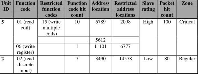
Once the signature engine inspects a packet and if it is not dropped, it would be passed on to the state based engine. The state based engine will keep track of certain parameters inside the packet. For example, the engine will cache the function code value, data read/write address location and the unit ID. The device will maintain a slave table, as shown in Table 3.2, and cache all the above mentioned parameters under the respective unit ID. Based on the SCADA protocol, additional parameters may be also be cached. It is important to know that this caching mechanism will happen only for the first packet that uses a unique function code. For subsequent packets with the same function code, only the address location will be cached. The unit ID will be used to match and compare entries in the slave table.
The slave table will also include a hit counter for every function code in order to track the use of function codes with every slave device. The SCADA administrator should be able to detect suspicious activity in the network by monitoring the slave table. The state engine could also be configured to generate a Simple Network Management Protocol (SNMP) alert if the hit
count on a function code exceeds a set threshold. For additional security, the administrator can define restricted function codes and address locations that should not be seen in any requests from the master. The engine will also drop such requests. Furthermore, a slave rating value will be set for every slave depending on its role in the SCADA network. A slave may be considered to have a high risk rating if it controls critical devices such as a power generator or a safety relay. On the other hand, a temperature recording system may be assigned low to medium risk rating. Based on this classification, the engine will perform additional tasks of generating authorization requests and SNMP alerts. Once the state engine inspects a packet, it will be forwarded out the respective interface where the intended slave is connected. The interfaces on the SSD can be categorized as trusted or untrusted depending on the position of the master station and the slaves. In addition to the above phases, security zones can be used to classify the slaves based on their importance. A set of slaves that play a vital role in the SCADA operation can be placed into a ‗critical‘ zone while other slaves can be classified into a ‗regular‘ zone. Once the zones are defined, every trusted interface of the SSD can be assigned to one of the defined zones.
TABLE 3.2 SLAVE TABLE Unit ID Function code Restricted function codes Function code hit count Address location Restricted address locations Slave rating Packet hit count Zone 5 01 (read coil) 15 (write multiple coils) 10 6789 2098 High 100 Critical 5612 06 (write register) 1 11101 6777 2 02 (read discrete input) 7 3490 14578 Low 80 Regular
3.4 Network Management using SNMP
SNMP is widely used in traditional networks for network monitoring purposes. The SNMP protocol polls data from several devices simultaneously and records it on an SNMP station. Device and network statistics such as rate of traffic, throughput, CPU and memory utilization, temperature and link status can be polled using SNMP. Network devices can also be configured to send traps to a monitoring server in case of specific events. In the SSD implementation, the device will be configured to send traps when an administrator authorizes a particular packet to be allowed or denied. Similarly, traps will be generated when a function use count exceeds a set threshold or a packet is dropped by the SSD. The network admin can keep track of the SNMP alerts on the monitoring station to understand network statistics and potential attack vectors in the SCADA network.
CHAPTER 4 SIMULATION
4.1 Modbus/TCP Testbed
In order to validate the SSD design, portions of the SSD architecture were implemented and tested. The testbed setup included a Modbus TCP client and server connected to an IP switched network as illustrated in Figure 4.1.
Figure 4.1 Modbus server and client with SSD inline
The Modbus client represents a SCADA master station and the server represents a slave device. The server and client were running the Windows operating system and had the MBAsyncServer [18] and PollMB [18] software installed on them respectively. As discussed in the SSD security architecture section, the SSD needs to be placed directly in front of the slaves. Therefore, to meet this requirement and to have the ability to connect multiple slaves, two VLANs were implemented on a layer 2 switch and the SSD bridged the two VLANs accordingly. From a network layer perspective, the client and server reside in the same IP subnet. When a packet is sourced from the client and destined to the server, the VLAN separation forces the packet to be
passed through the SSD before it reaches the destination, making it an inline solution. The design discussed above is used only for simulation purposes; however, in a real deployment the slaves can be directly connected to the SSD. To test the signature engine, Snort 2.9.0.3 was installed on a server running Fedora Linux. Signature rules were configured inside local.rules file and complied to detect Modbus packets with an invalid function code, protocol identifier or data length. The signature set also included rules to detect packets which were not sent to standard layer 4 ports. Snort allowed an action to be configured for each signature. For the validation tests, the actions were configured to alert whenever there was a match. The Modbus client software was used to generate invalid Modbus requests, and the signature engine was able to detect these malicious packets and produce alerts. These alerts could be further analyzed using Snort Report, which is a graphical interface for the Snort engine.
4.2 DoS Engine Implementation
The DoS engine was implemented as a dynamic preprocessor of Snort. It keeps track of every packet received by the SSD and helps maintain the master table. Based on a configured threshold, an alert is generated whenever the packet rate from a single IP address exceeds the threshold. The alert displayed the source IP address of the host generating the attack. The source code added to spp_example.c for the DoS engine is shown below.
unsigned int last_check_time = 0;
unsigned int check_threshold = 5; /* Check table every 5 seconds */ unsigned int counter_threshold = 50; /* Counter value to alert on */ uint32_t dos_src_ip[100] = {0};
unsigned int dos_counter[100] = {0}; unsigned int current_time;
IPV4Header *ipheader; int table_cnt;
_dpd.logMsg("Policy - %x, ex_config %x \n", policy_id, ex_config); sfPolicyUserPolicySet(ex_config, _dpd.getRuntimePolicy());
config = (ExampleConfig *)sfPolicyUserDataGetCurrent(ex_config); if (config == NULL) return; if (!p->ip4_header) { return; } ipheader = p->ip4_header; sourceip = ipheader->source.s_addr;
_dpd.logMsg("Source IP is %u\n", sourceip); for (table_cnt=0; table_cnt<100; table_cnt++)
{
if (dos_src_ip[table_cnt] == 0) {
/* This is a new source not yet in the table */ dos_src_ip[table_cnt] = sourceip; dos_counter[table_cnt] = 1; table_cnt = 100; } else { if (dos_src_ip[table_cnt] == sourceip) {
/* This is matching and existing entry in the table */ dos_counter[table_cnt]++; table_cnt = 100; } } } current_time = time(NULL); if (last_check_time == 0) { last_check_time = current_time;
_dpd.logMsg("First run, setting last_check_time to %u\n", current_time); return;
}
if ( (current_time-last_check_time) >check_threshold) {
/* It is time to see if any counters are over their thresholds. */ for (table_cnt=0; table_cnt<100; table_cnt++)
{
{
/* DOS Attack detected */
_dpd.logMsg("DOS Attack Detected, Source IP %u, Counter %u\n", dos_src_ip[table_cnt], dos_counter[table_cnt]); } dos_counter[table_cnt] = 0; } last_check_time = current_time; } 4.3 Attack scenario
An example attack scenario is illustrated in Figure 4.2, where a Modbus master and slaves reside on a shared Ethernet segment.
Figure 4.2 Sample attack scenario in a SCADA network
Suppose an attacker gains access to this network and passively listens to all traffic originated by the master. The attacker is also able to determine the IP addresses of the slave devices present on the network. Based on this information, the attacker can spoof the IP address and MAC address of the master and begin sending malicious packets to the slave devices. The
of the packets it receives. An attacker can thus modify a read request into a write request or store malicious code on the slave at a restricted memory address. Results discussed in the next chapter show how the SSD can detect invalid function codes or restricted addresses and drop such packets inline.
CHAPTER 5 RESULTS
5.1 Attack Prevention Case 1
In the first scenario, we assume that an attacker is able to get access to the SCADA internal network. If the attacker does not obtain a valid certificate, the SSD does not establish a TLS session and hence attacker packets are dropped. If the attacker makes an identity certificate request to the CA, the CA administrator won‘t recognize the device and will investigate the presence of a rogue device on the network. If the attacker generates a forged self-signed certificate and uses that during the TLS exchange, the SSD does not establish a TLS session since the certificate won‘t be signed by a trusted root CA server. As a result, the SSD protects a slave device from a spoofing attack.
5.2 Attack Prevention Case 2
In this scenario, suppose that the attacker is able to hack into a master station by using other hacking techniques. If this attack happens, the master‘s identity certificate is valid and the SSD will allow the compromised master to establish a successful TLS session. If an attacker targets a master station, the intent is probably to send read or write requests, or other commands that may crash the slaves or cause them to operate in an undesired way. The signature engine of the SSD inspects all packets before passing them to the slaves. The signature rules configured on the SSD restrict certain function codes, address locations and data values in order to prevent attacks. A few sample signature rules that are configured on the SSD are shown below. Snapshots of attack packets detected by the SSD are also illustrated.
Snort rules:
portvar Modbus_port [!502] var Modbus_slave [192.168.137.2] var Unknown_slave [!192.168.137.2]
1. To drop packets sent to unknown slave IPs
droptcp any any -> $Unknown_slave any (msg: ―Unknown slave IP‖; sid:1000001;) dropudp any any -> $Unknown_slave any (msg: ―Unknown slave IP‖; sid:1000002;)
Figure 5.1 Alert 1 generated by Snort engine 2. To prevent port scans and drop packets sent to unknown layer 4 ports
droptcp any any -> $Modbus_slave $Modbus_port (msg: ―Not Modbus traffic‖; sid:1000003;) dropudp any any -> $Modbus_slave $Modbus_port (msg: ―Not Modbus traffic‖; sid:1000004;)
3. To drop packets sent with an invalid protocol ID
droptcp any any -> any 502 (content: !―|00 00|‖; offset: 2; depth: 2; msg: ―Invalid Protocol ID‖; sid: 1000005;)
Figure 5.3 Alert 3 generated by Snort engine 4. To drop packets sent with a restricted function code 16
droptcp any any -> any 502 (content: ―|0f|‖; offset: 7; depth: 1; msg: ―Restricted function code 16‖; sid: 1000006;)
Figure 5.4 Alert 4 generated by Snort engine 5. To drop packets sent to a restricted address location
droptcp any any -> any 502 (content: ―|00 14|‖; offset: 8; depth: 2; msg: ―Restricted address location‖; sid: 1000007;)
Figure 5.5 Alert 5 generated by Snort engine 5.3 Attack Prevention Case 3
In this scenario, suppose that an attacker is able to gain access to the internal network by bypassing the network firewalls and intrusion prevention systems. Assume the attacker is also successful in compromising the master station or another host on the network. With the help of
the victim host, the attacker launches a DoS attack on a slave or set of slaves. In such an event, the SSD is able to detect the possibility of a DoS attack by monitoring the packet rate. Once the set threshold is exceeded, the DoS engine instructs the SSD to drop all packets sourced from the attacker‘s IP address.
5.4 Performance Analysis
A performance analysis of the SSD was done to determine its effect on the traffic rates and packet response times. The throughput was calculated for TCP traffic sent over a one-minute interval. TCP streams were generated using JPerf [19] with a maximum segment size of 1460 bytes and a window size of 56KBytes. Based on the tests, an average throughput of 85080 Kbps without the SSD and 84684 Kbps with the SSD was achieved. This TCP performance is shown in Figure 5.6. Although at a few instances we see better TCP throughput with the SSD inline, the deviation in the throughput can be attributed to other network traffic such as ARP and STP, which may affect the TCP throughput.
Figure 5.6 TCP performance with and without SSD 75000 77000 79000 81000 83000 85000 87000 89000 91000 93000 95000 1 3 5 7 9 11 13 15 17 19 21 23 25 27 29 31 33 35 37 39 41 43 45 47 49 51 53 55 57 59
B
an
d
wi
d
th
in
Kbps
Time in seconds
It is also important to understand the impact of implementing IPSEC in such a network. IPSEC is known to provide equal or sometimes better throughput on a network compared to TLS. The intent of this research, however, is to save the master and slaves from the computational overhead due to IPSEC. Research done in [20] shows that TLS requires less CPU resources as compared to IPSEC. Therefore, we can conclude that TLS minimizes the computational overhead on the devices and provides an acceptable bandwidth for TCP connections.
CHAPTER 6
CONCLUSION AND FUTURE WORK
The SSD architecture described in this thesis enhances the security of SCADA protocols and SCADA networks. The SCADA security device does not allow a master station or any other external device to establish communication directly with the remote units (slaves). The proposed design incorporates security features such as data confidentiality, integrity and device authentication which normally lacks in SCADA networks. Security objectives are accomplished without adding computational overhead on the end devices. The other benefits of this approach are that it does not require changes in the SCADA protocols or topology, or need hardware migration of network devices. The SCADA security device combines firewalling and intrusion prevention techniques together without having the need of separate devices. Furthermore, much of the implementation is based on open source projects and established protocols such as OpenSSL, Snort and SNMP. This approach will prove beneficial from a security standpoint for newer protocols that are tailored to suit the needs of the Smart grid.
In future, the SSD can be tested in a real SCADA network once the TLS proxy feature is fully implemented. The master stations would also need software that would enable them to establish a TLS session with the SSD. Access to real SCADA data would allow the user to understand flows, throughput, delay and other traffic characteristics. The thresholds configured on the SSD can be tweaked according to the network conditions. The state table can be developed further to accommodate other SCADA protocols such as DNP3 and ICCP. Additions to the signature database will help keep track of unknown or newer threats. On a large scale, multiple SSDs can be configured to communicate with each other and exchange event data. This would be a great step forward to achieve proactive detection capability using event correlation.
This research has not focused on securing the network links between the SSD and slaves. The security of these dynamic links can be attributed to physical security, depending on where the slaves are located. However, in the future, slaves may be equipped with an enhanced TCP/IP stack that will allow implementation of TLS or other security techniques. They may also have the computational resources needed to implement encryption and decryption in hardware. Such developments can lead to further research in this area.
REFERENCES
[1] Smart Grid Stakeholder Books - Technology providers, The U.S. Department of Energy by Litos Strategic Communication under contract No. DE-AC26-04NT41817, Subtask 500.01.02
[2] NIST, Framework and Roadmap for Smart Grid Interoperability Standards, Release 1.0 (Jan. 2010) (NIST Special Publication 1108)
[3] Modadugu, N., Rescorla, E. The Design and Implementation of Datagram TLS. Proceedings of NDSS, 2004.
[4] Falliere, Nicolas, Liam Murchu, and Eric Chien. "W32 Stuxnet Dossier." Symantec. Symantec, 01 Feb 2011. Web. 8 Nov 2011. <http://www.symantec.com/content/en
/us/enterprise/media/security_response/whitepapers/w32_stuxnet_dossier.pdf>.
[5] "Racom - Protocol DNP3 for Morse." Racom. Racom, 11Jan2011. Web. 6 Nov 2011. <http://www.racom.eu/eng/support/prot/dnp3/index.html>.
[6] Modbus-IDA. " Modbus messaging on TCP/IP implementation guide V1.0b ." 2006. [7] The Snort project <http://www.snort.org>
[8] Coates, G.M., Hopkinson, K.M., Graham, S. and Kurkowski, S. A Trust System Architecture for SCADA Network Security. IEEE Transactions on Power Delivery, 25(1). 158-169.
[9] Ten, C., Liu, C. and Manimaran, G. Cybersecurity for Critical Infrastructures: Attack and Defense Modeling. IEEE Transactions on Systems, Man and Cybernetics, Part A: Systems and Humans, 40(4). 853-865.
[10] Kobayashi, T.H., Batista, A.B., Brito, A.M. and Pires, P.S.M. Using a Packet Manipulation Tool for Security Analysis of Industrial Network Protocols, in Emerging Technologies and Factory Automation, (Patras, Greece, 2007), IEEE, 744-747.
[11] Yellamandamma, N., Rao, K.V.H., Sai Kumar, T. and Aggarwal, A. Low cost solution for automation and control of MV substation using Modbus-SCADA in International Conference on Power Systems, (Kharagpur, India, 2009), IEEE, 1-6.
[12] Ericsson, G.N. Cyber Security and Power System Communication—Essential Parts of a Smart Grid Infrastructure. IEEE Transactions on Power Delivery, 25(3). 1501-1507. [13] Ten, C., Liu, C. and Manimaran, G. Vulnerability Assessment of Cybersecurity for
[14] Creery, A.A. and Byres, E.J. Industrial cybersecurity for a power system and SCADA networks - Be secure. Industry Applications Magazine, IEEE, 13(4). 49-55.
[15] West, A. Securing DNP3 and Modbus with AGA12-2J.in Power and Energy Society General Meeting - Conversion and Delivery of Electrical Energy in the 21st Century, (Pittsburgh, PA, 2008), IEEE , 1-4.
[16] Hadziosmanovic, D., Bolzoni, D. and Hartel, P. Towards Securing SCADA Systems Against Process-Related Threats. IEEE Transactions on Smart grid: Special Issue on Cyber, Physical and System Security of Smart grid, 1-10.
[17] Wang, L., Mander, T., Cheung, H., Nabhani, F. and Cheung, R. Security Operation Modes for Enhancement of Utility Computer Network Cyber-Security.in Power Engineering Society General Meeting, (Tampa, FL, 2007), IEEE, 1-8.
[18] Griffin, Mike. "Software." MBlogic. MBLogic, n.d. Web. 8 Nov 2011. <http://mblogic.sourceforge.net/software/software.html>.
[19] Grove, Andy. "JPerf." JPerf. Sourceforge, n.d. Web. 8 Nov 2011. <http://sourceforge.net/projects/jperf/>.
[20] Kotuliak, I., Rybár, P., Trúchly, P. Performance Comparison of IPsec and TLS Based VPN Technologies. 9th IEEE International Conference on Emerging eLearning Technologies and Applications, (Slovakia, 2011), IEEE, 217-221.
[21] NISTIR 7628. Guidelines for Smart grid Cyber Security: Vol. 1, Smart grid Cyber Security Strategy, Architecture, and High-Level Requirements. The Smart grid Interoperability Panel – Cyber Security Working Group
[22] M. Majdalawieh, F. Parisi-Presicce, and D. Wijesekera. DNPSec: Distributed Network ProtocolVersion 3 (DNP3) Security Framework. In Advances in Computer, Information, andSystems Sciences, and Engineering: Proceedings of IETA 2005, TeNe 2005, EIAE 2005, pages227–234. Springer, 2006.
![Figure 2.2 Control field in the DNP3 packet header [5]](https://thumb-us.123doks.com/thumbv2/123dok_us/1080682.2643769/25.918.135.786.138.317/figure-control-field-dnp-packet-header.webp)