Programming spindle speed variation for machine tool chatter
suppression
Emad Al-Regib
a, Jun Ni
a,∗, Soo-Hun Lee
baDepartment of Mechanical Engineering and Applied Mechanics, The University of Michigan, 1023 H.H. Dow Building, 2300 Hayward Street,
Ann Arbor, MI 48109, USA
bSchool of Mechanical and Industrial Engineering, Ajou University, Suwon, South Korea Received 22 June 2000; received in revised form 15 April 2003; accepted 8 May 2003
Abstract
This paper presents a novel method for programming spindle speed variation for machine tool chatter suppression. This method is based on varying the spindle speed for minimum energy input by the cutting process. The work done by the cutting force during sinusoidal spindle speed variation S3V is solved numerically over a wide range of spindle speeds to study the effect of S3V on stable and unstable systems and to generate charts by which the optimum S3V amplitude ratio can be selected. For on-line application, a simple criterion for computing the optimal S3V amplitude ratio is presented. Also, a heuristic criterion for selecting the frequency of the forcing speed signal is developed so that the resulting signal ensures fast stabilization of the machining process. The proposed criteria are suitable for on-line chatter suppression, since they only require knowledge of the chatter frequency and spindle speed. The effectiveness of the developed S3V programming method is verified experimentally.
2003 Elsevier Ltd. All rights reserved.
Keywords: Chatter; Precision machining; Spindle speed variation; Stability; Numerical analysis; Vibration control
1. Introduction
One of the most significant factors affecting the per-formance of machine tools is chatter. Chatter not only limits productivity of cutting processes but also causes poor surface finish and reduced dimensional accuracy, increases the rate of tool wear, results in a noisy work-place and reduces the life of a machine tool. Chatter can be avoided by keeping a low depth of cut, however this leads to low productivity. Over the years, various methods have been developed to avoid regenerative chatter without reducing the depth of cut. The basic prin-ciple of these techniques is to prevent the dynamic of the machining process from locking on the most favor-able phase for chatter.
Slavicek[16] and Vanherck[25]proposed the use of milling cutters with non-uniform tooth pitch and Stone [20]used end mills with alternating helix. Effectiveness
∗ Corresponding author. Fax:+1-734-936-0363.
E-mail address: [email protected] (J. Ni).
0890-6955/$ - see front matter2003 Elsevier Ltd. All rights reserved. doi:10.1016/S0890-6955(03)00126-3
of these methods in chatter suppression has been verified by simulation and experiments [3,6,23]. These tech-niques can be applied to the design of a non-uniform pitch cutter for a specific cutting condition, but cannot be applied to single point machining.
Weck et al. [26] utilized on-line generated stability lobes to select a spindle speed so that maximizes the depth-of-cut limit. Later, Smith and Tlusty [17], Delio et al. [2]and Tarng et al.[22] avoided the need for the knowledge of the stability lobes and proposed that the best tooth passing frequency be made equal to the chatter frequency. This minimizes the phase between the inner and outer modulations. This approach is adaptive in the sense that the spindle speed is changed based on feed-back measurement of the chatter frequency. This method is practical for high spindle speed machining when the stability lobes are well separated.
Another technique to suppress regenerative chatter is sinusoidal spindle speed variation (S3V) around the
mean speed to disturb the regenerative mechanism. Since this technique was introduced by Stoferle and Grab[19], there have been many research efforts to verify its
effec-tiveness on machining stability by numerical simulation and experiments in turning[7,8,14,15,21,28]and in mill-ing[1,8,9]. Despite the above research efforts, this tech-nique has not been implemented widely in industry because there is no systematic way to select the proper amplitude and frequency of the sinusoidal forcing signal. The selection of these parameters depends on the dynamics of the machining system and is constrained by the spindle-drive system response and its ability to track the forcing speed signal. In addition, variable speed machining can result in an adverse effect and may even cause chatter in an otherwise stable process[5,10,15,24]. This usually occurs when this method is applied to high speed machining. Recently, Soliman and Ismail[18] pro-posed using fuzzy logic to select on-line the amplitude and frequency of the forcing speed signal. Yilmaz et al. [27]generalized sinusoidal spindle speed variation tech-nique by introducing multi-level random spindle speed variation, where the spindle speed is varied in random fashion within the maximum amplitude ratio allowed by the spindle-drive.
In this paper, a systematic procedure for designing a stabilizing spindle speed, by selecting the effective amplitude and frequency of the forcing speed signal, is developed. The remainder of the paper is summarized as follows. In Section 2, the theoretical background of machining process modeling is reviewed. Based on energy analysis, the effect of S3V amplitude ratio on
stability is investigated in Section 3. The work done by the cutting force during S3V is solved numerically over
a wide range of spindle speed to generate charts by which the optimum S3V amplitude can be selected.
Sec-tion 4 develops a simple criterion for computing the opti-mum S3V amplitude ratio, based on the spindle speed
and chatter frequency. Also, a criterion to select the minimum effective S3V frequency is proposed. Section
5 presents experimental verification results. Conclusions follow in Section 6.
2. Theoretical background
Machine tool chatter is a self-excited vibration caused by the interaction of the chip removal process and the structure of the machine tool. The most important type of chatter is regenerative chatter, which occurs mainly when a favorable phase relationship develops between the inner and outer modulations caused by vibration dur-ing two consecutive tooth passes.
The conventional model of a single degree of freedom machining system is shown in Fig. 1. In this model, the resultant cutting force F(t) is proportional to the instan-taneous uncut chip thickness h(t) as expressed by:
Fx(t)⫽Kcb h(t), (1)
where b is the axial depth of cut and Kc is the static
Fig. 1. Model for single degree-of-freedom machining system. cutting stiffness. The instantaneous uncut chip thickness
h(t) composed of the mean uncut chip thickness ho, the inner modulated cut surface x(t), due to the current tooth pass, and the outer modulated surface x(t⫺t), due to the previous tooth pass. Hence, the instantaneous uncut chip thickness can be written as
h(t)⫽h0 ⫹x(t)⫺mx(t⫺t). (2)
Here t is the time delay between two consecutive cuts and represents the regenerative feedback effect. It is related to the spindle speed, S in (rpm), by
t⫽60
zS, (3)
where z is the number of teeth on the cutter (z = 1 in turning). The quantity zS / 60 is the tooth passing fre-quency in (Hz) and mis the overlapping factor and will be assumed here to bem=1 for maximum regenerative effect. The structure dynamics is represented by the ori-ented transfer function G(s). The regenerative chatter can be represented by control block diagram as shown in Fig. 2 [11].
The closed–loop system can be represented by the second order system:
x¨(t)⫹2zwnx˙(t)⫹w
2
nx(t)⫽Kcb [x(t)⫺x(t⫺t) (4)
⫹ho]
where z is the damping ratio and wn is the natural fre-quency of the machining system. This model can be used to study the stability of the machining system under both constant and variable spindle speeds where the spindle speed S=S(t) and the time delayt=t(t) are time-vary-ing functions.
The characteristic equation of the constant speed machining system can be derived as
1⫹Kcb (1⫺e⫺t s
)G(s)⫽0. (5) Let s =jw, then the above equation can be rewritten as
⫺1 2 ⫹j
sinwt
2(1⫺coswt)⫽Kcb [Real[G] (6)
⫹jImag[G]].
The quantitywtis the phase angle f (radians) of the regenerative wave on the machined surface, where wis the vibration frequency (rad/sec). From Eq. (3), the relation between the spindle speed, vibration frequency, and the phase angle can be expressed:
wt⫽f⫽60w
zS . (7)
It is convenient to express this phase angle as an integer number of waves N plus a fractional portion of a wave e/ 2p such that if there are N + e/ 2p vibration waves during one revolution of the workpiece, where
N = 0, 1, 2,% and 0ⱕe/ 2p ⬍ 1, then the relation
between the spindle speed, the vibration frequency, and the phase angle is:
60w
zS ⫽f⫽2pN⫹e (8)
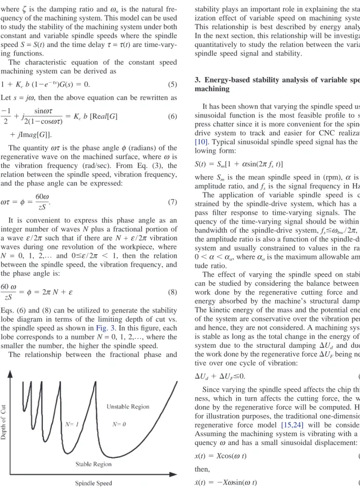
Eqs. (6) and (8) can be utilized to generate the stability lobe diagram in terms of the limiting depth of cut vs. the spindle speed as shown inFig. 3. In this figure, each lobe corresponds to a number N=0, 1, 2,%, where the
smaller the number, the higher the spindle speed. The relationship between the fractional phase and
Fig. 3. Typical stability lobe diagram.
stability plays an important role in explaining the stabil-ization effect of variable speed on machining systems. This relationship is best described by energy analysis. In the next section, this relationship will be investigated quantitatively to study the relation between the variable spindle speed signal and stability.
3. Energy-based stability analysis of variable speed machining
It has been shown that varying the spindle speed using sinusoidal function is the most feasible profile to sup-press chatter since it is more convenient for the spindle-drive system to track and easier for CNC realization [10]. Typical sinusoidal spindle speed signal has the fol-lowing form:
S(t)⫽Sm[1⫹asin(2pfst)] (9)
where Sm is the mean spindle speed in (rpm), a is the amplitude ratio, and fs is the signal frequency in Hz.
The application of variable spindle speed is con-strained by the spindle-drive system, which has a low pass filter response to time-varying signals. The fre-quency of the time-varying signal should be within the bandwidth of the spindle-drive system, fsⱕwbw/ 2p, and the amplitude ratio is also a function of the spindle-drive system and usually constrained to values in the range 0⬍a⬍aa, whereaais the maximum allowable ampli-tude ratio.
The effect of varying the spindle speed on stability can be studied by considering the balance between the work done by the regenerative cutting force and the energy absorbed by the machine’s structural damping. The kinetic energy of the mass and the potential energy of the system are conservative over the vibration period and hence, they are not considered. A machining system is stable as long as the total change in the energy of the system due to the structural damping ⌬Ud and due to the work done by the regenerative force⌬UFbeing nega-tive over one cycle of vibration:
⌬Ud⫹ ⌬UFⱕ0. (10)
Since varying the spindle speed affects the chip thick-ness, which in turn affects the cutting force, the work done by the regenerative force will be computed. Here, for illustration purposes, the traditional one-dimensional regenerative force model [15,24] will be considered. Assuming the machining system is vibrating with a fre-quency w and has a small sinusoidal displacement:
x(t)⫽Xcos(wt) (11)
then,
x˙(t)⫽ ⫺Xwsin(wt) (12)
x(t⫺t)⫽Xcos(wt⫺wt). (13) The validity of this assumption for variable speed mach-ining has been verified in Zhang [28].
For variable speed machining, the phase angle wt is time-varying [12,28], which is expressed using Eqs. (7) and (9) as: wt⫽60w zS(t)⫽ 60w zSm[1⫹asin(2pfst)] . (14) Substituting in Eq. (13): x(t⫺t)⫽Xcos
冉
wt⫺ 60w zSm[1⫹asin(2pfst)]冊
. (15) The work undertaken by the regenerative force overn integer cycles of vibration can be computed from
the relation:
⌬UF⫽
冕
2pn /w
0
⫺F(t) x˙(t) dt. (16)
Substituting for the regenerative force from Eqs. (1) and (2) into Eq. (16): ⌬UF⫽
冕
2pn /w 0 ⫺Kcb [x(t)⫺x(t⫺t) (17) ⫹h0] x˙(t) dt.After substituting Eqs. (11), (12), and (15) into Eq. (17)
⌬UF⫽ ⫺Kcb
冕
2pn /w 0冋
Xcos(wt)⫺Xcos冉
wt ⫺ 60w zSm[1⫹asin(2pfst)]冊
⫹h0册
[⫺wXsin(wt)]dtand performing part of the integration, the work done by the regenerative force can be found to be:
⌬UF⫽ ⫺wKcb X2
冕
2pn /w 0 (18) cos冉
wt⫺ 60w zSm[1⫹asin(2pfst)]冊
sin(wt) dtwhere the number of vibration cycles is expressed by [12]:
n⫽ w
(2p)2f
s
. (19)
The average work done by the regenerative force over one vibratory cycle is computed by dividing Eq. (18) by the number of cycles (n) from Eq. (19):
⌬UF⫽ ⫺(2p)2fsKcb X2
冕
2pn /w 0 (20) cos冉
wt⫺ 60w zSm[1⫹asin(2pfst)]冊
sin(wt) dt.The closed form solution of this equation has been approximated using Bessel functions[28] to investigate the effect of S3V parameters on stability. Radulescu et
al.[19]solved it numerically to explain qualitatively the robustness of variable speed machining on stability aug-mentation.
Here, Eq. (20) will be solved numerically for wide range of mean spindle speed by considering the follow-ing relation between the vibration frequency and the mean spindle speed:
60w
zSm
⫽2pNm⫹em (21)
where Nm is the lobe number and em is the fractional phase associated with the mean spindle speed. Substitut-ing in Eq. (20) and rearrangSubstitut-ing:
⌬UF KcbX2 ⫽ ⫺(2p)2 f s
冕
2pn /w 0 (22) cos冉
wt⫺ 2pNm⫹em [1⫹asin(2pfst)]冊
sin(wt) dt.For constant speed machining, where the amplitude ratio is a = 0 and the number of cycles is n = 1, Eq. (22) can be solved analytically [4]:
⌬UF KcbX2
⫽ ⫺sinem. (23)
When 0 ⬍ em ⬍ p, the variation in the chip thickness leads the tool movement and consequently, the energy introduced to the system in the cycle is smaller than the energy dissipated and the system is stable. When p⬍ em⬍2p, the variation in the chip thickness lags the tool movement and consequently, the energy introduced to the system in the cycle is larger than the energy dissi-pated and the system is unstable [9,13,29].
For variable speed machining, Eq. (22) does not have a closed form solution. The right hand side of the above equation can be computed numerically to investigate the effect of the variable spindle speed signal on the work done by the regenerative force. Eq. (22) is only a func-tion of the lobe number Nm, the fractional phase em, and the amplitude ratio a:
⌬UF KcbX
2⫽fun(Nm,em,a) (24)
since varying the variable spindle speed signal’s fre-quency fshas no effect on the computed integration. Eq. (22) is solved numerically over wide range of Nm, em, andato investigate the effect of S3V amplitude ratio on
the stability when S3V is applied to unstable and stable
machining systems especially at high speed machining. In addition, the optimum S3
V amplitude ratio, which minimizes the work undertaken by the regenerative
cut-ting force in Eq. (22) is computed numerically and tabu-lated in charts as function of Nm andem.
3.1. S3V effect on stable system
In order to investigate the effect of S3V amplitude
ratio on the stability when S3V is applied to a stable
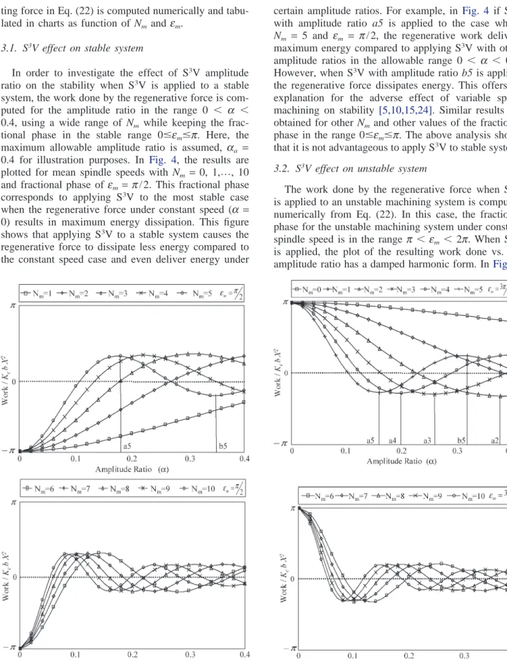
system, the work done by the regenerative force is com-puted for the amplitude ratio in the range 0 ⬍ a ⬍ 0.4, using a wide range of Nm while keeping the frac-tional phase in the stable range 0ⱕemⱕp. Here, the maximum allowable amplitude ratio is assumed, aa = 0.4 for illustration purposes. In Fig. 4, the results are plotted for mean spindle speeds with Nm = 0, 1,%, 10
and fractional phase of em= p/ 2. This fractional phase corresponds to applying S3V to the most stable case
when the regenerative force under constant speed (a = 0) results in maximum energy dissipation. This figure shows that applying S3V to a stable system causes the
regenerative force to dissipate less energy compared to the constant speed case and even deliver energy under
Fig. 4. Effect of S3V amplitude on the work done by the regenerative force when S3V is applied to a stable system.
certain amplitude ratios. For example, in Fig. 4 if S3V
with amplitude ratio a5 is applied to the case where
Nm = 5 and em = p/ 2, the regenerative work delivers maximum energy compared to applying S3V with other
amplitude ratios in the allowable range 0 ⬍ a ⬍ 0.4. However, when S3V with amplitude ratio b5 is applied,
the regenerative force dissipates energy. This offers an explanation for the adverse effect of variable speed machining on stability [5,10,15,24]. Similar results are obtained for other Nmand other values of the fractional phase in the range 0ⱕemⱕp. The above analysis shows that it is not advantageous to apply S3V to stable system.
3.2. S3V effect on unstable system
The work done by the regenerative force when S3V
is applied to an unstable machining system is computed numerically from Eq. (22). In this case, the fractional phase for the unstable machining system under constant spindle speed is in the range p⬍ em⬍ 2p. When S3V is applied, the plot of the resulting work done vs. the amplitude ratio has a damped harmonic form. In Fig. 5,
Fig. 5. Effect of S3V amplitude on the work done by the regenerative force when S3V is applied to an unstable system.
the work done by the regenerative force is plotted for mean spindle speeds with Nm=0, 1,%, 10 and fractional
phase of em = 3p/ 2. This fractional phase corresponds to the maximum energy delivered by the regenerative force to the system under constant speed, i.e. for ampli-tude ratio a= 0.Fig. 5 shows that applying S3V to an
unstable system always reduces the work done by the regenerative force compared to the constant speed case and consequently S3
V enhances the stability of the sys-tem. However, some amplitude ratios are more effective than others. For example, inFig. 5if S3V with amplitude
ratio a5 is applied to the case where Nm=5, the regener-ative work dissipates maximum energy compared to applying S3V with other amplitude ratios in the
allow-able range of 0 ⬍ a ⬍ 0.4. However, when S3V with
amplitude ratio b5 is applied, the regenerative force delivers energy. The figure also shows that there is only a single optimal amplitude ratio that results in maximum energy dissipation by the regenerative force. In Fig. 5, the points (a2, a3, a4, a5) correspond to the optimal amplitude ratios for the five cases under consideration. Also, it can be noticed from the figure that the higher the nominal speed (the smaller Nm) the larger the ampli-tude ratio required for the work to start dissipating energy. For example, for Nm= 0,1, there is no optimal amplitude ratio in this allowable range 0 ⬍ a ⬍ 0.4. This explains why S3V is less effective in stabilizing
machining systems with low dominant frequency at high spindle speed than it is at lower speeds [14,17]. This is because at such high spindle speeds, applying S3V with
amplitude ratio in the range of 0 ⬍ a ⬍ 0.4 always causes the regenerative force to deliver energy to the system. However, this energy is less than the one deliv-ered under constant speed machining.
3.3. Optimal S3V amplitude ratio
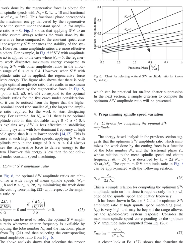
In Fig. 6, the optimal S3V amplitude ratios are
tabu-lated for a wide range of mean spindle speeds (Nm= 2,%, 8 andp⬍em⬍2p) by minimizing the work done
by the cutting force in Eq. (22) with respect to the ampli-tude ratio a: ∂
冉
⌬UF KcbX2冊
∂a ⫽0 and ∂2冉
⌬UF KcbX2冊
∂a2 ⬎0. (25)This figure can be used to select the optimal S3V
ampli-tude ratio whenever chatter frequency is available by computing the lobe number Nmand the fractional phase em from Eq. (21) and then selecting the corresponding optimal amplitude ratio from Fig. 6.
The above analysis shows that selecting the proper S3V amplitude is crucial when S3V is applied to suppress
chatter in machining. This motivates the development of a criterion for selecting the proper S3
V amplitude ratio,
Fig. 6. Chart for selecting optimal S3V amplitude ratio for known
Nmandem.
which can be practical for on-line chatter suppression. In the next section, a simple criterion to compute the optimum S3V amplitude ratio will be presented.
4. Programming spindle speed variation 4.1. Criterion for computing the optimal S3V amplitude
The energy-based analysis in the previous section sug-gests that the optimum S3
V amplitude ratio which mini-mizes the work done by the cutting force is a function of the lobe number Nm and the fractional phase em, whose relation to the mean spindle speed and chatter frequency, wc = 2p fc, is described by em + 2p Nm = 60 wc/ zSm. The optimum S3V amplitude ratio inFig. 6 can be approximated with the following relation: aopt⬇
em 2pNm
. (26)
This is a simple relation for computing the optimum S3V
amplitude ratio on-line since it requires only the knowl-edge of the spindle speed and chatter frequency.
It has been shown in Section 3.2 that the optimum S3V
amplitude ratio at high spindle speed machining (small
Nm) is very high and may be beyond the range allowed by the spindle-drive system response. Consider the maximum spindle speed corresponding to the optimum S3V amplitude ratio computed from Eq. (26):
SMax|opt⫽ 60wc 2pz Nm
. (27)
A closer look at Eq. (27), shows that changing the spindle speed to the maximum speed is equivalent to the spindle speed selection method [17,22], where the stabilizing spindle speed is selected without variation so
that the ratio between the chatter frequency and the spindle speed in (rad/sec) (tooth passing frequency in milling) is an integer. Hence, when the optimal ampli-tude ratio computed using Eq. (26) is higher than the allowable range for the spindle-drive system, the spindle speed selection method can be applied instead of the S3V.
4.2. Criterion for selecting S3V frequency
Although, S3V frequency is not as critical as the
amplitude ratio[8,12], researchers showed by simulation and experiments that the effectiveness of S3V cannot be
realized unless the S3V frequency is increased beyond a
minimum value [7,8,14,15]. Also, selecting S3
V fre-quency is constrained by the spindle-drive? system. Hence, a criterion for selecting the minimum effective S3V frequency is required to determine whether such
minimum value exceeds the bandwidth of the spindle-drive system.
Since the S3V frequency determines how fast the
energy is dissipated from the machining system when variable spindle speed is applied, the proposed criterion can be stated as follows. The work done by the regener-ative force should start dissipating energy from the sys-tem within at most one rotation of the spindle (one tooth pass in milling) after applying the spindle speed vari-ation. This means that if the variable spindle speed after one tooth pass (at time t = 60
zSm
) is denoted by Sf, then the corresponding fractional phase denoted by ef and defined by the relation
ef⫹2pNm⫽ 60wc
z Sf
(28) should reach the value ef = p(i.e. leaving the unstable region p ⬍ em ⬍ 2p) within one spindle rotation after applying the S3V. The spindle speed at time (t =60 / z
Sm) is expressed by: S(t)⫽S
冉
60 z Sm冊
⫽Sf⫽ 60wc (p⫹2pNm) z . (29) From the sinusoidal spindle speed function S(t), another relation can be obtained for Sf:S(t)⫽S
冉
60 z Sm冊
⫽Sf⫽Sm冋
1⫹asin冉
2pfs 60 z Sm冊册
(30) where fsis the S3V frequency to be computed. Eqs. (29) and (30) can be solved simultaneously for the S3Vfre-quency: fs⫽ z Sm 120psin ⫺1
冉
60wc az Sm(p⫹2pNm) ⫺a1冊
. (31)For on-line application, this equation is computed using the optimal amplitude ratio obtained from Eq. (26).
5. Experimental results
5.1. Application to turning process
This section analyzes the effects of S3V on chatter
suppression in turning process of a cylindrical work-piece. Experiments were carried out on a Novamat N 50-1 horizontal CNC lathe with no tailstock. The cutting conditions are shown inTable 1.
A LabView software module and an I/O board are used to generate the S3V signal. The signal is then sent
through the spindle speed override to the CNC, which controls the AC motor driving the lathe spindle through belt and gear group transmission. The input speed com-mand, actual spindle speed signal from the tachometer, and the acceleration signal from a PCB W353B15 (10 mV/g sensitivity) accelerometer placed on top of the tur-ret were first passed through a PCB signal conditioner and recorded during the experiments.
In order to determine the allowable range for the para-meters of the sinusoidal signal, the spindle-drive sys-tem’s response to sinusoidal signal has been determined experimentally. The bandwidth of the spindle-drive sys-tem is found to be 1 Hz. This is the maximum allowable frequency for the variable spindle speed signal. It is also found that the maximum allowable amplitude ratio is 0.25.
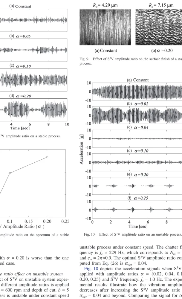
5.1.1. S3V effect on stable system
In this section, an experimental case is presented where the S3V can have an adverse effect on machining.
S3V with different amplitude ratios is applied at spindle
speed Sm = 600 rpm and depth of cut, b = 2 mm to a stable process. Fig. 7 shows the acceleration signal for the stable process under constant speed and the acceler-ation signals when S3V is applied with amplitude ratios
a = {0.05, 0.10, 0.20} and S3V frequency f
s = 0.5 Hz. The experimental results reveal how the vibration ampli-tude increases with increasing the S3V amplitude ratio.
InFig. 8, the maximum power in the spectra correspond-ing to the signals in Fig. 7 is plotted with respect to the S3
V amplitude ratios. Fig. 9 depicts the workpiece topography along with the Ra values of the surface roughness for the constant speed cutting and S3V case
with a= 0.20. The figure shows that the surface finish
Table 1
Cutting conditions
Workpiece material Carbon steel 1018
Workpiece dimensions Length, 180 mm; diameter, 35 mm Cutting insert TP 100 coated Carboloy SNMA 644 Insert dimensions 3 / 4⬙×3 / 4⬙×1 / 4⬙with 1 / 16⬙nose radius Tool holder Carboloy MSDNN85-6, neutral shank
with 45oside cutting edge angle
Fig. 7. Effect of S3V amplitude ratio on a stable process.
Fig. 8. Effect of S3V amplitude ratio on the spectrum of a stable process.
for the S3V case with a = 0.20 is worse than the one
for the constant speed case.
5.1.2. S3V amplitude ratio effect on unstable system To study the effect of S3V on unstable system
exper-imentally, S3V with different amplitude ratios is applied
at spindle speed Sm= 600 rpm and depth of cut, b= 5 mm where the process is unstable under constant speed cutting. Fig. 10a shows the acceleration signal for the
Fig. 9. Effect of S3V amplitude ratio on the surface finish of a stable process.
Fig. 10. Effect of S3V amplitude ratio on an unstable process. unstable process under constant speed. The chatter fre-quency is fc = 229 Hz, which corresponds to Nm = 22 andem=2p∗0.9. The optimal S3V amplitude ratio com-puted from Eq. (26) is aopt=0.04.
Fig. 10 depicts the acceleration signals when S3V is
applied with amplitude ratios a = {0.02, 0.04, 0.10, 0.20, 0.25} and S3V frequency, f
s=1.0 Hz. The experi-mental results illustrate how the vibration amplitude decreases after increasing the S3V amplitude ratio to
aopt = 0.04 and beyond. Comparing the signal for aopt
= 0.04 with the signals for higher S3
the figure shows that the acceleration signal for S3V
withaopt=0.04 does not have transients with relatively high vibration amplitude. Fig. 11 shows the workpiece topography along with the Ra values of the surface roughness for the constant speed case, S3V with a
opt = 0.04, and S3V with a= 0.20, respectively. The surface
finishes are better for the cases with S3V cutting than
the one for constant speed, and the surface finish corre-sponding to aopt =0.04 has better quality than the one for S3
V with a= 0.20.
The maximum power in the spectra corresponding to the signals inFig. 10are plotted with respect to the S3V
amplitude ratios in Fig. 12a. In this figure, the power in the spectrum drops sharply after increasing the S3V
amplitude ratio toaopt=0.04 and beyond. Also, the fig-ure shows that the spectrum corresponding for S3V with
aopt =0.04 has the minimum power.
Experiments are also conducted to investigate the effect of S3V amplitude ratio on the power spectrum
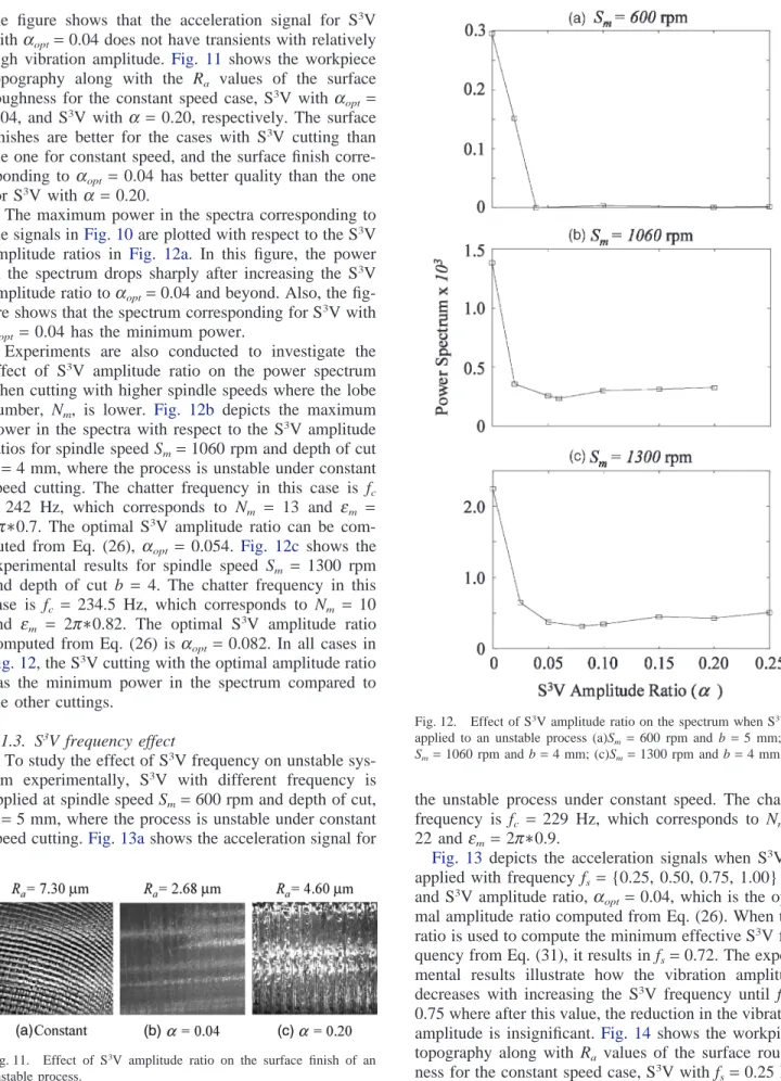
when cutting with higher spindle speeds where the lobe number, Nm, is lower. Fig. 12b depicts the maximum power in the spectra with respect to the S3V amplitude
ratios for spindle speed Sm=1060 rpm and depth of cut b=4 mm, where the process is unstable under constant speed cutting. The chatter frequency in this case is fc
= 242 Hz, which corresponds to Nm = 13 and em = 2p∗0.7. The optimal S3V amplitude ratio can be
com-puted from Eq. (26), aopt = 0.054. Fig. 12c shows the experimental results for spindle speed Sm = 1300 rpm and depth of cut b = 4. The chatter frequency in this case is fc = 234.5 Hz, which corresponds to Nm = 10 and em = 2p∗0.82. The optimal S3V amplitude ratio computed from Eq. (26) is aopt=0.082. In all cases in Fig. 12, the S3V cutting with the optimal amplitude ratio
has the minimum power in the spectrum compared to the other cuttings.
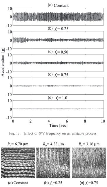
5.1.3. S3V frequency effect
To study the effect of S3V frequency on unstable
sys-tem experimentally, S3V with different frequency is
applied at spindle speed Sm=600 rpm and depth of cut, b=5 mm, where the process is unstable under constant speed cutting.Fig. 13ashows the acceleration signal for
Fig. 11. Effect of S3V amplitude ratio on the surface finish of an unstable process.
Fig. 12. Effect of S3V amplitude ratio on the spectrum when S3V is applied to an unstable process (a)Sm= 600 rpm and b=5 mm; (b) Sm=1060 rpm and b=4 mm; (c)Sm=1300 rpm and b=4 mm.
the unstable process under constant speed. The chatter frequency is fc = 229 Hz, which corresponds to Nm = 22 and em=2p∗0.9.
Fig. 13 depicts the acceleration signals when S3V is
applied with frequency fs ={0.25, 0.50, 0.75, 1.00} Hz and S3V amplitude ratio, a
opt=0.04, which is the opti-mal amplitude ratio computed from Eq. (26). When this ratio is used to compute the minimum effective S3V
fre-quency from Eq. (31), it results in fs=0.72. The experi-mental results illustrate how the vibration amplitude decreases with increasing the S3V frequency until f
s = 0.75 where after this value, the reduction in the vibration amplitude is insignificant. Fig. 14 shows the workpiece topography along with Ra values of the surface rough-ness for the constant speed case, S3
V with fs =0.25 Hz, and S3
Fig. 13. Effect of S3V frequency on an unstable process.
Fig. 14. Effect of S3V frequency on the surface finish of an unstable process.
surface finishes are better for the cases with S3V cutting
than the one for constant speed, the surface finish corre-sponding to fs=0.75 Hz has better quality than the one for S3V with f
s =0.25 Hz. The maximum power in the spectra corresponding to the signals inFig. 13is plotted with respect to the S3V frequency in Fig. 15a. In this
figure, the power in the spectrum decreases with increas-ing the S3V frequency until f
s=0.75 Hz where after this value, the power level almost stays the same.
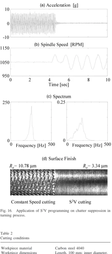
5.1.4. Example: Application of S3V programming on chatter suppression
In this experiment, the proposed method to program S3V, by selecting the optimal effective amplitude ratio
and effective frequency, is applied to suppress chatter in turning process of a cylindrical workpiece. The mean spindle speed is Sm =1050 rpm and the depth of cut is
Fig. 15. Effect of S3V frequency on the spectrum of an unstable pro-cess.
b = 5 mm. Under constant speed cutting, chatter develops with frequency,fc = 250 Hz. When chatter is fully developed, S3V is applied with optimum amplitude
ratio, aopt= 0.05 and frequency fs = 0.9 Hz, which are computed from Eqs. (26) and (31), respectively.
Fig. 16a shows the acceleration signal during both constant and variable speed cutting. The actual spindle speed signal from the tachometer is depicted inFig. 16b. The spectra of the acceleration signals, before and after applying S3V, are shown in Fig. 16c. Fig. 16d depicts
the surface finish of the workpiece, during constant speed and S3V cuttings, along with the corresponding
surface roughness, Ra values. These figures reveal clear comparisons between the acceleration signal amplitude level together with the surface finish in the case of con-stant speed cutting and S3V cutting regions.
5.2. Application to boring process
The criteria developed in this paper to program S3V
are verified by comparing the results obtained from Eqs. (26) and (31) with experimental results from design of experiment approach conducted by an industrial partner to set the effective S3V amplitude ratio and frequency
to suppress chatter in a boring process. The cutting con-ditions are shown in Table 2.
In this process, constant speed results in unstable cut-ting with a high-pitched sound and chatter marks are clearly visible on the machined surface. The chatter fre-quency of 200 Hz is clearly seen in the spectrum. The spindle-drive system’s response to sinusoidal signal is determined experimentally. The bandwidth of the spindle-drive system is found to be 2.3 Hz and the maximum allowable amplitude ratio is 0.30.
In the dsign of experiment, S3
V is applied with a range of S3
Fig. 16. Application of S3V programming on chatter suppression in turning process.
Table 2
Cutting conditions
Workpiece material Carbon steel 4040
Workpiece dimensions Length, 100 mm; inner diameter, 115 mm; outer diameter, 135 mm
Spindle speed 673 rpm
Feed-rate 300 mm/min
Depth of cut 2 mm
0.25, 0.30}, and frequencies, fs = {0.5, 1.0, 1.5, 2.0}. That is, 24 combinations of amplitude and frequency are applied consuming 24 workpieces. Out of the 24 combi-nations, the combination of S3
V amplitude ratio a兩exp = 0.05 and frequency fs兩exp= 0.5 Hz was the most
suc-cessful in suppressing the chatter while all other combi-nations resulted in minor improvement. In Fig. 17a–c, the input spindle speed, the accelerometer signal and its power spectrum are shown for constant cutting and the S3V case (with amplitude ratio of a兩
exp =0.05 and
fre-quency fs兩exp=0.5 Hz). The intensity in the power
spec-trum for S3V cutting is smaller than the one for the
con-stant spindle speed. The surface finish of the workpiece is shown inFig. 17dfor both the constant spindle speed and S3
V cases where the effect of S3
V can be visualized more clearly.
In order to verify the effectiveness of the proposed criteria in predicting the effective amplitude and quency, Eqs. (26) and (31) are computed for chatter fre-quency fc = 200 Hz and mean spindle speed Sm = 673 rpm to giveaopt=0.049 and fs =0.69 Hz, respectively. These results are in close agreement with the parameters found by the design of experiment procedure.
6. Conclusions
In this paper, a systematic procedure for programming spindle speed variation signal’s amplitude and frequency
Fig. 17. Application of S3V programming on chatter suppression in boring process.
is developed. The criteria for selecting the S3V
ampli-tude ratio give results close to the optimum ampliampli-tude ratio computed numerically from minimizing the work done by the machining force. At high spindle speed machining, the optimum S3V amplitude ratio is very
high and beyond the allowable range by available spindle-drive systems. Hence, applying another tech-nique, such as the spindle speed selection method [17], is more feasible. The proposed criterion for selecting the S3
V frequency is based on how fast the regenerative energy is dissipated from the machining system. The proposed criteria are suitable for on-line S3V
program-ming since the only requirement is knowledge of the chatter frequency and the spindle speed. The effective-ness of the developed method is verified experimentally.
Acknowledgements
The authors acknowledge the partial financial support from NSF grant EEC-9526519 and the NSF-I/UCR Center for Dimensional Measurement and Control in Manufacturing at the University of Michigan. E. Al-Regib acknowledges the financial support by King Fai-sal Foundation.
References
[1] Y. Altintas, P.K. Chan, In process detection and suppression of chatter in milling, Int J Mach Tools Manuf 32 (1992) 329–347. [2] T. Delio, J. Tlusty, S. Smith, Use of audio signal for chatter
detec-tion and control, ASME J Eng Industry 114 (1992) 146–157. [3] P. Doolan, M. Phadke, S. Wu, Computer design of a
vibration-free face-milling cutter, ASME J Eng Industry 97 (1975) 925. [4] W. Endres, A quantitative energy-based method for predicting
stability limit as a direct function of spindle speed for high-speed machining, Trans NAMRI/SME XXIV (1996) 27–32.
[5] R. Engelhardt, S. Lin, R. DeVor, S. Kapoor, A verification of the use of variable spindle speed for vibration reduction in face mill-ing, in: Proc NAMRC, 1989, pp. 115–122.
[6] H. Fu, R. DeVor, S. Kappor, The optimal design of tooth spacing in face milling via a dynamic force model, in: Proc 12th NAMRC, 1984, pp. 291–297.
[7] T. Hoshi, N. Sakisaka, I. Moriyama, M. Sato, Study for practical application of fluctuating speed cutting for regenerative chatter control, Annals of the CIRP 25 (1977) 175–179.
[8] T. Inamura, T. Sata, Stability analysis of cutting under varying spindle speed, J Faculty of Eng, The University of Tokyo (B) XXXIII (1) (1974).
[9] A.C. Lee, C.S. Liu, Analysis of chatter vibration in the end mill-ing process, Int J Mach Tools and Manuf 31 (4) (1991) 471–479.
[10] S.C. Lin, R.E. Devor, S.G. Kapoor, The effects of variable speed cutting on vibration control in face milling, ASME, J Eng Indus-try 112 (1990) 1–11.
[11] H.E. Meritt, Theory of self-excited machine tool chatter contri-bution to machine-tool chatter: Contricontri-bution to machine-tool chatter, research 1, ASME Paper No. 64-WA-Prod-13 (1964). [12] R. Radulescu, S. Kapoor, R. DeVor, An investigation of variable
spindle speed face milling for tool-work structures with complex dynamics: Parts I and II, ASME, J Manuf Sci Eng 119 (1997) 266–280.
[13] R. Radulescu, S. Kapoor, W. Endres, R. DeVor, An investigation of the vibration of the face milling process during high speed machining, Trans NAMRI/SME XXi (1993) 237–245.
[14] J.S. Sexton, R.J. Stone, An investigation of the transient effects during variable speed cutting, J Mech Eng Sci 22 (3) (1980) 107–118.
[15] J.S. Sexton, R.J. Stone, The stability of machining with continu-ously varying spindle speed, Annals of CIRP 24 (1978) 321–326. [16] J. Slavicek, The effect of irregular tooth pitch on stability in
mill-ing, in: Proc 6th MTDR Conf, 1965, pp. 15–22.
[17] S. Smith, J. Tlusty, Stabilizing chatter by automatic spindle speed regulation, Annals of the CIRP 41 (1992) 433–436.
[18] S. Soliman, F. Ismail, Chatter suppression by adaptive speed modulation, Int J Mach Tools Manuf 37 (3) (1997) 355–369. [19] T. Stoferle, H. Grab, Vermeiden von Ratterschwingungen durch
Periodische Drehzahlanderung, Werkstatt und Betrieb 105 (1972) 727–730.
[20] B.J. Stone, The effect on the chatter behavior of machine tools of cutters with different helix angles on adjacent teeth, in: Proc 11th MTDR, 1970, pp. 169–180.
[21] T. Takemura, T. Kitamura, T. Hoshi, Active suppression of chat-ter by programmed variation of spindle speed, Annals of CIRP 23 (1974) 121–122.
[22] Y. Tarng, Y. Hseih, T. Li, Automatic selection of spindle speed for suppression of regenerative chatter in turning, Int J Adv Manuf Technol 11 (1996) 12–17.
[23] J. Tlusty, W. Zaton, F. Ismail, Stability lobes in milling, Annals of the CIRP 32 (1983) 309–313.
[24] T. Tsao, M. McCarthy, S. Kapoor, A new approach to stability analysis of variable speed machining systems, Int J Mach Tools Manuf 33 (6) (1993) 791–808.
[25] P. Vanherck, Increasing milling machine productivity by use of cutter with non-constant cutting-edge pitch, in: Proc Adv MTDR Conf, No. 8, 1967, pp. 947–960.
[26] M. Weck, E. Verhang, M. Gather, Adaptive control for face-mill-ing operations with strategies for avoidface-mill-ing chatter vibrations and for automatic cut distribution, Annals of the CIRP 24/1 (1975) 405–409.
[27] A. Yilmaz, E. Al-Regib, J. Ni, Machine-tool chatter suppression by multi-level random spindle speed variation, in: Symposium on Recent Advances in Machine Tool, ASME, Mechanical Engin-eering Congress and Exposition, Nashville, Tennessee, 1999. [28] Zhang, H., Chatter modeling, analysis and control for cnc
mach-ining systems, PhD dissertation, The University of Michigan, 1996.
[29] H. Zhang, J. Ni, Phase difference and its sensitivity analysis for a nonlinear difference-differential machining chatter model, Trans NAMRI XXIII (1995) 131–136.
![Fig. 2. Block diagram of regenerative chatter loop [13].](https://thumb-us.123doks.com/thumbv2/123dok_us/1744049.2745920/2.897.456.824.95.1080/fig-block-diagram-regenerative-chatter-loop.webp)