for Smart Metering and Smart Grid
David von OheimbSiemens Corporate Technology, Munich, Germany
Abstract. The power grid is currently undergoing changes towards
highly volatile and localized energy production and storage, supported by IT and communication components. Smart Metering is going to provide fine-grained measurement and automatic remote reading of consumption and production amounts. It enables flexible tariffing and dynamic load optimization, ultimately aiming at cost and consumption reduction. The related security requirements are mainly authenticity, integrity, and pri-vacy of metering data. Even more challenging is grid automation, which is critical for the safety and availability of the grid. The overall situation calls for an integrated security architecture that not only addresses all relevant security threats but also satisfies functional, safety, performance, process integration, and economic side conditions.
In this article, we summarize and evaluate the IT security architecture and security requirements prescribed by the German BSI in their Smart Meter Gateway Protection Profile and related documents. For instance, there are problems regarding the integration of the required security module and multicast communication. We contrast their requirements with alternatives offering better protection against sophisticated local attacks and with a much simpler approach to communication security, which focuses on the core security needs of smart metering and is suitable for grid automation in distribution networks as well. We provide a formal model and analysis of the latter solution w.r.t. communication security.
1
Introduction
1.1 The Concept of Smart Grid
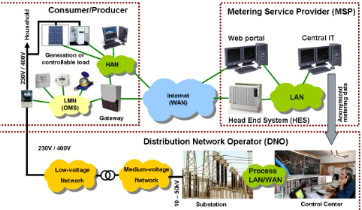
The networks for supplying electricity and other commodities like gas and wa-ter are getting more and more dynamic, due to localized and volatile produc-tion (e.g., using solar power), possibly storage (e.g., in batteries of e-cars), and market-driven consumption. To cope with this situation, the so-called “smart grid” is being developed and deployed. This is a commodity network that dy-namically integrates the behavior and actions of all connected entities — both energy suppliers and consumers — in a non-trivial way. To this end, secure use of information and communication technology (ICT) components is crucial. A smart grid has two main functional aspects.
Grid automation is required to maintain the safety, availability, and perfor-mance of the grid. Already from the electrical engineering perspective, con-trolling and constantly stabilizing a large grid of many more and more dy-namic and non-linear components under strong real-time requirements is a huge problem. On the other hand, major cost reductions can be expected because in this way dynamic load peaks may be avoided that would oth-erwise require very costly reinforcements of existing statically dimensioned distribution networks.
Smart metering is the fine-grained and flexible reading and automatic report-ing of consumption or production. Its main aim is to save energy and costs in interplay with market mechanisms like commodity brokerage, while it can also be used to optimize the overall load distribution and stability of the grid. Yet so far it is unclear if smart metering will actually lead to an over-all cost and consumption reduction and if it will be accepted (unless under legislative coercion) by more than a minority of private consumers. [12] Smart metering and grid automation may share part of the equipment installed at the sites of consumers and/or producers (referred to below as prosumers). For instance, metering gateways in households may in addition forward grid automation commands of the network operator, used for load switching and controlling local electricity production. Yet there are also advantages of keeping the two grid aspects independent.
Smart metering requires communication links between a vast number of dis-tributed prosumers within an area like a city or nation and one or more meter
data management (MDM)and billing services. The entities involved include
cen-tralhead end systems (HES)collecting metering data fromterminal nodes (TNs)
located in premises of the prosumers. Terminal nodes include smart meters, and optionally also gateways and remotely controllable devices. So-called data
con-centrators (DC) may be used to gather and forward information sent between
the HES and the TNs. Communication may take place over all kinds of media, including low-bandwidth networks like power line communication (PLC), radio signal (GSM), or DSL. Figure 1depicts the overall scenario.
1.2 Smart Grid Security
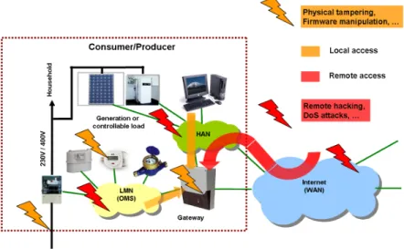
Like in any other ICT system, smart metering and grid automation poses func-tionality, security, and real-time requirements that need to be fulfilled holistically and in a technically and economically adequate way. Security threats include tampering of meter data in order to manipulate the outcome of billing, leakage of private information, in particular related to the lifestyle and monetary situ-ation of consumers, and the manipulsitu-ation of grid control commands, which can threaten the whole grid. See for instance [11] for a more detailed derivation of se-curity requirements.Figure 2shows thelocal metrological1network (LMN),home
area network (HAN), and an optional gateway connecting them with the wide
area network (WAN). Potential attack points can be grouped into local/physical
access and remote access (i.e., over the Internet).
Fig. 2.Local networks including gateway with attack points
Countermeasures must protect the overall flow of commands and data among the parties involved. Their effectiveness should be verified by certification, for instance according to theCommon Criteria (CC)[7].
Particular challenges arise due the scale of a smart grid and because its components are widely distributed in the field (and thus expensive to main-tain by physical access). For this and other reasons the components need to be very stable and long-lived, which increases the spatial and temporal exposure to potential attackers. Moreover, for the conventional grid (like for many other industrial systems) it has been sufficient to counter security threats by physical means (in particular, simply by locking rooms housing critical components), but this does not hold any more with the substantial inclusion of easily accessible and more or less well-known ICT components.
1
1.3 National and International Approaches
Germany’s energy market is highly deregulated, which renders the situation more complex than in most other countries. Central and regional commodity provi-sion is unbundled into collaboration of independent institutions. There are not only rather large utilities, but also many network operators, billing services, and potentially further service providers. This not only causes high organizational overhead, but also further functional and interoperability requirements and com-plications w.r.t. responsibility and trust. As detailed inSec. 2, the German Fed-eral Office for Information security (BSI) [3] and the T ¨UV Informationstechnik GmbH (T ¨UViT) [25] — in partial collaboration with DKE, ZVEI, and other industrial associations — are trying to address these needs by providing security and interoperability requirements for smart metering.
In Austria, rather vague security requirements [10] came into effect in 2011:
Die intelligenten Messger¨ate sowie ihre Kommunikation [...] sind nach
anerkanntem Stand der Technik abzusichern und zu verschl¨usseln, um
Unberechtigten den Zugriff nicht zu erm¨oglichen. Die Kommunikation
[...] ist nach dem Stand der Technik mit einem individuellen
kundenbe-zogenen Schl¨ussel zu authentisieren und zu verschl¨usseln.
More substantial requirements are currently under development. They appear to be inspired to some extent by the German BSI’s requirements, yet still much more pragmatic and less limiting, allowing for a considerably better cost-/benefit ratio and a broader applicability also for other nations.
In several countries smart meters are already heavily used – Italy having so far the world’s largest smart meter deployment – but with essentially no security in place. For obvious reasons, this has already lead to a high volume of fraud and thus considerable economic damage, as reported [14] at least for the U.S. and Puerto Rico. Local privacy breaches apparently are of minor practical interest, while excessive central accumulation and misuse of personal data could become a real problem [1, §2.1 and§3.1].
There are currently several national and international research, industry, standardization, and regulation groups aiming to provide guidance towards se-curing various aspects of smart grids. For instance, a task force of the European Smart Meters Coordination Group (SM-CG) is drafting a document on privacy and security [23]. Similarly, there is the Advanced Metering Infrastructure Secu-rity (AMI-SEC) task force [19] of the Open Smart Grid User’s Group producing technical specifications that may be used by utilities to assess and procure secu-rity related functionality.
1.4 Structure of This Article
InSec. 2 we summarize and evaluate the security requirements by the German BSI for smart meter gateways. The protection of gateways and similar devices using a hardware security module is discussed inSec. 3, whileSec. 4 introduces a lean and efficient alternative approach to securing for securing communication within smart grids, in particular for smart metering applications. We conclude in Sec. 5with more general remarks on establishing security in the given domain.
2
The German BSI’s Smart Meter Gateway PP
The upcoming smart metering infrastructure in Germany revolves around a spe-cific component: the smart meter gateway (GW). It is going to be placed on the premises of private or commercial prosumers and serve as the communica-tion unit between their local devices, namely smart meters (for possibly multiple commodities), as well as any controllable consumption, storage, or production devices, with central metering related service providers.
2.1 History
In 2010, the German ministry for economics and technology,Bundesministerium
f¨ur Wirtschaft und Technologie (BMWi), commissioned the federal office for
information security,Bundesamt f¨ur Sicherheit in der Informationstechnik (BSI)
[3], to provide aProtection Profile (PP)for smart metering gateways.
According to the Common Criteria [7] approach, a protection profile shall define — in an implementation-independent way — the security objectives and resulting minimum functional and assurance requirements for itsTarget of
Eval-uation (TOE), which is a smart metering gateway in this case. It is directed
mainly to developers implementing instances of the TOE and is going to serve as a common reference for evaluating and certifying all smart metering gateways deployed in Germany.
Since mid-2011, partly to ensure interoperability of smart metering devices, a number of detailed technical implementation guidelines have been developed, calledTechnische Richtlinie (TR) 3109[6].
Document preparation was in fact mostly done by T ¨UViT [25] in the name of BSI. Several commenting rounds with industry groups have been executed, where a high amount of feedback has been provided and partly considered in revisions of the respective documents.
Due to significant delays in the definition process, the deadline according to §21e of the Energy Industry Act,Energiewirtschaftsgesetz (EnWG)for manda-tory installation of certified metering equipment at sites with more than 6.000 kWh annual consumption was postponed by two years until end-2014. In early 2013, the BSI’sSmart Meter Gateway Protection Profile (SMGW-PP)[4] and a related PP [5] were close to finalization.
2.2 TOE Overview
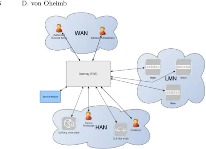
The TOE of the SMGW-PP is an electronic unit comprising hardware and soft-ware, similar to a DSL router for Internet access of PCs in households. Similarly to the scenario described above, the gateway connects a Wide Area Network
(WAN)with aLocal Metrological Network (LMN)of smart meters and aHome
Area Network (HAN)of so-calledControllable Local Systems (CLS)and displays
optionally used by prosumers to check their bills.Figure 3illustrates the TOE in its environment, including the roles Gateway Administrators and other Autho-rized External Entities, as well as Consumers and Service Technicians. As will be detailed below, the TOE is required to integrate a HW Security Module.
Fig. 3.The BSI’s smart metering gateway in its context
The security functionality aims at protecting the confidentiality, authenticity, integrity of metering data and ensuring information flow control, in order to protect the privacy of consumers, to ensure reliable billing, and to contribute to the protection of the smart metering system itself and of the overall grid. 2.3 Security Problem Definition
Assets
The security assets identified for the smart metering gateway are: – consumption and production data (billing-relevant)
– grid status data and log data (not billing-relevant) – gateway time
– gateway, meter, and CLS configuration data – gateway firmware (including its updates)
– supplementary data (optionally passed by the gateway between any further central services and devices in the LMN or HAN)
All these assets need integrity and authenticity protection. For all of them except for gateway time and firmware also confidentiality protection is required. Assumptions
The following assumptions are made from the gateway perspective.2
A.ExternalPrivacy: Authorized and authenticated external entities and their applications receiving any kind of privacy-relevant data or billing-relevant data do not perform any unauthorized analysis.
A.TrustedAdmins: The central GW administrator and any service technicians are trustworthy and well-trained.
2
A.PhysicalProtection: The gateway (and the meters) is installed in a non-public environment within the premises of the prosumers, which provides a basic level of physical protection.
A.ProcessProfile: The profiles governing the processing of data are correct. A.Update: Software updates have undergone certification and their authors
are trustworthy.
A.Network.1 A WAN network connection with a sufficient reliability and bandwidth for the individual situation is available.
A.Network.2: One or more trustworthy sources for an update of the system time are available in the WAN.
A.Network.3: The gateway is the only usable communication gateway for me-ters in the LMN.
A.Network.4: Any additional connections of devices in the HAN to parties in the WAN are appropriately protected.
Attackers
Two types of attackers are considered:
Remote attackers are located in the WAN trying to compromise the confi-dentiality and/or integrity of data transmitted via the WAN, or trying to conquer a component of the local infrastructure via the WAN to cause dam-age to a component itself or to the grid.
Local attackers including prosumers, have physical access to the gateway and/or meters and will try to read out or alter assets without authoriza-tion while stored or transmitted in the LMN. They are assumed to have less motivation than remote attackers, since a successful local attack is believed to impact a single gateway only.
From the assets, their protection needs, and possible attackers considered, a list of straightforward threats is derived (which are left out here).
Regarding security assurance requirements (SAR), the BSI requires evalu-ation assurance level (EAL) 4 (methodically designed, tested and reviewed), augmented by AVA VAN.5 (advanced vulnerability analysis; resistance to high attack potential) and ALC FLR.2 (life-cycle support; flaw reporting procedures) as defined in [7, Part 3]. No justification for the selection of this level of assurance is provided.
Organizational Security Policies
The BSI’s PP also defines twoorganizational security policies (OSP).
OSP.SM: The TOE shall use the services of a certified hardwaresecurity
mod-ule (SM)for the verification and generation of digital signatures, key
agree-ment and storage, and random number generation.
OSP.Log: The TOE shall maintain a system log that is analyzed automatically, a prosumer log, and a calibration log as defined in [6]. Further, the TOE shell limit access to the information in the logs.
Note that the PP authors misuse OSPs for requiring specific technical solutions, while according to [7], OSPs should be used to state general policies at the same logical level as security threats and assumptions.
2.4 Security Objectives
As usual, the objectives for the TOE’s environment (OE.Profile, OE.SM, OE.ExternalPrivacy, OE.PhysicalProtection, OE.Update, OE.Network, and OE.TrustedAdmins) directly correspond to the respective assumptions and OSPs. The security objectives for the TOE itself are: 3
O.Firewall The TOE shall serve as the connection point for internal to external entities, yet not allow any connections originating from the WAN — except for a specifically signedwakeup call— to entities of the LMN and HAN (as long as they use the gateway).
O.SeparateIF The TOE shall have physically separated ports for the LMN, the HAN, and the WAN. It shall automatically detect, during its self-test, any wrong (wired or wireless) connections.
O.Conceal To protect the privacy of its consumers, the TOE shall conceal the communication with outside parties in the WAN to ensure that no privacy-relevant information may be obtained by analyzing the frequency, load, size or the absence of external communication.
O.Meter The TOE receives or polls information about the consumption or pro-duction of commodities from one or multiple meters and is responsible for handling this data securely. This includes encryption, signing, pseudonymiza-tion, the correct use of processing profile, and traffic management.
O.Crypt The TOE shall provide cryptographic functionality for protecting the communication with entities in the WAN, LMN, and HAN, replay detection for all communications with external entities, and encryption of the persis-tently stored security functions and user data. In addition the TOE shall generate the required keys utilizing the security module and ensure that the keys are only used for an acceptable amount of time and then destroyed. O.Time The TOE shall provide reliable time stamps and update its internal
clock in regular intervals by retrieving reliable time information from a ded-icated reliable source in the WAN.
O.Protect The TOE shall implement functionality to protect its security func-tions against malfuncfunc-tions and tampering. Specifically, the TOE shall over-write any information that is not longer needed, implement a self-test, have a fail-safe design that ensures that no malfunction can impact the delivery of a commodity, make any physical manipulation within the scope of the in-tended environment detectable for the prosumer and gateway administrator. O.Management The TOE shall provide functions for managing security fea-tures via the WAN side interface only and ensure that only authorized gate-way administrators can make changes in the behavior of the security func-tions. The TOE shall implement a secure mechanism to update the firmware. O.Log The TOE shall maintain a system log that is analyzed automatically, a prosumer log, and a calibration log as defined in [6]. Further, the TOE shall limit access to the information in the logs.
O.Access The TOE shall control the access of users to information and func-tions via its external interfaces.
3
Clearly, this list does not only include high-level security objectives, as would be their purpose according to the CC [7]. It contains many low-level design decisions towards technical solutions that go much beyond stating abstract security goals. 2.5 Security Functional Requirements
The lowest level of requirements in a protection profile constitute the so-called
security functional requirements (SFRs), which define by which technical means
the security objectives for the TOE are to be met. Here we only present in heavily abbreviated form the extensive list of SFRs given in [4,§6].
1. Communication security
– establishment of trusted channels with meters and other entities – transport-level protection on all channels (using TLS v1.1) – detection and disregard of re-played data
– re-authentication of external entities at least after 48 hours or after trans-mission of 5 MB of data, i.e., mandatory session re-negotiation (not just re-keying)
– attribute-based complete information flow control via firewall
– communication concealing: regular transmission of data (independent of commodity consumption)
2. Cryptography support
– asymmetric encryption and signing with Elliptic Curve Cryptography (ECC-256)
– integrity checking with Secure Hash Algorithm (SHA-256)
– symmetric encryption according to Advanced Encryption Standard (AES-128)
– mandatory use of certified hardware security module (HSM) – random number generation (according to BSI AIS 20 / AIS 31) 3. Local key/certificate management with mandatory use of full PKI
– local generation of public/private key pairs for TLS and of secret keys for protected communication with battery-powered meters
– confidential and tamper-proof storage of key material on HSM
– management of key material (Update of outdated or compromised keys) for PKI
– full certificate chain checking including CRLs – key management for connected meters and CLS 4. Meter data handing
– application-level encryption and digital signatures
– secure time-stamping of meter data with maximum deviation
– pseudonymization where PII is not strictly needed (to support data pro-tection requirements)
– protected prosumer and calibration logs with review support and over-flow handling
5. User management
– authentication of users (prosumers, etc.) before any action – re-authentication every 10 minutes or after each command – complete security attribute based access control
6. Device management
– physical tamper protection and detection
– stored data integrity monitoring and action; device self-tests – full residual information protection
– attribute-based access to management functions
– protected system log with review support, overflow handling, automatic incident analysis and security alarms
– secure gateway software update 2.6 Evaluation
The present protection profiles [4,5] and their related technical implementation guidelines [6] offer a number of strong points, including:
– clear security requirements for smart metering gateways
– high assurance level of a critical smart metering system component – a strong national standard ensuring interoperability of devices
On the other hand, they have several drawbacks:
– one-sidedness of the overall security architecture: heavy protection mecha-nisms are required for smart metering gateways only
– high technical overhead: multiple layers of protection, use of full-fledged
Public-Key Infrastructure (PKI), mandatory use of a HW security module
(HSM), and point-to-point connections using TLS
– high costs4 per gateway, due to the large number of security features to be implemented, certified at a high assurance level, and used
– high organizational overhead and running expenses for the overall system operation, in particular regarding the assumed PKI services
– use of a classical PKI: exploiting any vulnerabilities in its critical central components may cause enormous damage to the whole system [15]
– inclusion of much limiting detail, leaving only minimal freedom of design – insecure HSM integration due to design issues — seeSec. 3
– requirements ruling out efficient real-time communication – neglect of DoS protection
Concerning several of the issues listed, more detailed comments follow. Overall System Security
Of course, demanding mechanisms like encryption and digital signatures for mes-sages sent or received by the gateways implicitly calls for the respective mecha-nisms at their communication partners, in particular the head end system(s) — yet to our knowledge no actual regulation exists for them and other parts of the metering infrastructure, except for the PKI requirements given in [6, Part 4]. The central services should deploy further protection mechanisms, for instance plau-sibility checks for metering and status data received from the gateways. These should be stated at least in the form of assumptions on the TOE environment.
4
both per installation and during operation: its power consumption was estimated at 10 W, which corresponds to around 1% of the site’s overall electricity consumption.
Attacker Model and Assurance Level
It remains unclear why a relatively high assurance level (EAL4) with assumed highest attack potential (AVA VAN.5) has been chosen.We’d see the need for high assurance only if the gateway played a critical role for the safety and stabil-ity of the grid. The high assurance for gateways may drive the focus of potential attackers to other parts of the system (such as central systems and local meters), putting the high overhead for securing the gateway component at question.
Local manipulation of billing data may be done by much simpler means than by hacking the gateway, for instance by tampering with meter sensors or their physical connections (e.g., bridging electrical contacts). Also the motivation for a local attacker to obtain private information from the gateway is presumably rather low — in particular since, being locally present, he has much simpler and more interesting ways of spying on his victim(s) than accessing their commodity consumption data processed and stored temporarily in the gateway.
A relatively minor issue is that the argumentation given in [4,§3.4: Threats] (as well as in [5,§3.4: Threats]) is incomplete:
the [...] threat model assumes that the local attacker has less motivation than the WAN attacker [...]. An attacker who has to have physical access to the TOE that they are attacking, will only be able to compromise one TOE at a time. So the effect of a successful attack will always be limited to the attacked TOE.
What has been overlooked here is that a highly motivated WAN attacker may get access to a gateway, for instance by owning or entering any building where such a gateway is installed and used. He does not only have all the possibilities of a remote attacker on the Internet, but if he manages to locally hack a gateway, his possibilities might grow. First, he can then act as an apparently valid node in the system, which might increase his attack potential on the overall smart metering infrastructure, in particular in case local meter readings are used for grid automation purposes. On the other hand, the overall system architecture should be designed and implemented in a way such that compromised individual gateways have only local effect. Second, he may gain knowledge about the gate-way’s implementation that could be useful when attacking similar gateways even remotely over the WAN. On the other hand, the security of a product should not rely on the obscurity of its design and implementation.
The main disadvantage that the local interface has for an attacker, namely that it does not give access to other gateways located elsewhere, is indepen-dent of any level of local protection — simply because it is infeasible for the attacker to visit many places where gateways are installed. Since moreover (as observed) the motivation and potential damage of local attacks is limited, their local protection becomes secondary. (This also limits the usefulness of the as-sumption A.PhysicalProtection, quoted above, that the gateway is installed in an environment offering a basic level of protection).
We conclude that a high protection level (including the use of a HW security module) against local attacks on gateways is not justified, and that an overall medium level (EAL3 + AVA VAN.4) should be sufficient.
Real-Time Communication Requirements The assumption A.Network.1, namely
a WAN network connection with a sufficient reliability and bandwidth for the individual situation is available
is not necessarily realistic, since households might not have data network con-nections beyond a classical telephone line or a GSM connection. Even when they have high-bandwidth connections, there are no guarantees5 that they can be used as the carrier for the gateway’s WAN connections. There is of course the obvious possibility to use the power line itself to transmit data via PLC, yet this technology is not widely installed, and if so, it does have non-negligible bandwidth constraints.
Moreover, the bandwidth consumption in the WAN induced by the BSI’s requirements is higher than it could be, for two reasons:
– Even though the bandwidth penalty induced by already established TLS connections is relatively low, the requirement to re-establish WAN connec-tions at least every 48 hours (and every 5 MB of data transferred) places an undue burden for PLC based data transmission: a large number (say, a thousand) of gateways compete on the limited bandwidth per substation and are forced to perform relatively data intense connection re-establishment, in-cluding re-authentication of each connected external entity.
– All WAN connections are required to sue TLS — and thus point-to-point — connections, which is very inefficient for multicasting/broadcasting configu-ration data, software updates, and grid automation commands. The latter are particularly critical because they typically have tight real-time (i.e, la-tency) requirements, which are impossible to meet on a large number of parallel TLS connections on a PLC-based network. For all the mentioned message types, confidentiality protection is not needed at all, such that digi-tal signatures in combination with replay protection would be sufficient, but such a type of message transfer is plainly not possible using TLS.
A further general problem is that the connections within the LMN typically have critical bandwidth and availability limitations, in particular when wireless meters are used and the gateway or the meter is installed in a steel cabinet, for instance in the basement of a building. The PP and related TRs respect this issue to some extent by allowing efficient AES-based protection for wireless me-ter connections. On the other hand, it is not realistic to require TLS channels (at least occasionally for the exchange of master keys) for meters connected via bidirectional wireless communication. Wired connections for meters are gener-ally very expensive — if not impossible — to install. Moreover, both types of connections may easily get cut off (or shielded, respectively) by accident or on purpose by local attackers.
5
for simple practical reasons such as the following:
availability of local connectivity at the place where the gateway is installed, liability concerns and data tariff’s limitations, data transmission costs, and extended periods of unavailability in particular for over-the-air connections.
3
Securing Devices in the Field
Given also their experience with hardware security chips, the BSI chose in 2010 to mandate the use of a so-calledSecurity Module (SM)for secure storage and use of critical key material in smart meter gateways. This has been advocated and advertised by the security chip industry [13]. Yet their claims did not materialize:
Likewise certified gateways can easily be developed to incorporate smart card controllers. Consequently the implementation of the BSI protection profile will not delay the introduction of a secure smart meter network.
3.1 Fundamental Considerations w.r.t. Use of HSMs
The use of an already certified smart card chip has advantages in terms of certification effort for the gateway and personalization process improvements, but not necessarily in terms of actual security. As pointed out to the BSI, the BMWi, and various representatives of the smart grid related industry in mid to end 2011, the intended use of a hardware security module (SM) only superficially increases the security of the smart meter gateway.
From a security architect’s perspective, concerning the SM there are three types of attackers to consider.
– Remote attackers, which have no access to the gateway hardware. When accessed from remote, a hardware SM and any alternative software imple-mentation of its cryptographic and storage functionality are interchangeable (except for irrelevant performance differences).
– Local attackers who do not try or do not succeed hacking the gateway (be-cause their motivation or skill level is not high enough). These attackers will not even reach the SM’s functionality, and therefore the hardware SM is not needed to protect from such attackers.
– Local attackers who do succeed hacking the gateway itself (because they have a sufficiently high attack potential), obtaining control over those hard-ware and softhard-ware portions outside the security module. Also if they do not manage to hack into the SM, they may simply abuse its services and in ef-fect corrupt all uses of the gateway. For instance, even without getting hold of any key stored in the SM, they may issue signing commands and thus effectively sign any (fake) data in the name of the given gateway.
That is, in any case the use of the SM does not effectively increase assurance. 3.2 Authentication of HSM Users
A way to handle the particularly problematic third item would be to authenticate each critical use of the SM. This was not foreseen in the earlier versions of the PPs and TRs. After we reported this issue in one of the official commenting rounds, the SM commands GENERAL AUTHENTICATE and EXTERNAL AUTHENTICATE have been added to the current versions of the TR [6, Part 2] and PP for the SM [5].
The SM can authenticate other parties like the gateway administrator, yet there is no chance for (the rest of) the gateway itself to securely interact with the SM, in particular to authenticate using any form of secret stored in the gateway’s memory. Despite of this problem, [5] contains a respective (practically unfulfillable) assumption:
A.OperationalPhase:It is assumed that appropriate technical and/or organizational measures in the operational phase of the integrated gate-way guarantee for the confidentiality, integrity and authenticity of the assets [...]. In particular, this holds for key and PIN objects stored, gen-erated and processed in the operational phase of the integrated gateway.
Nevertheless, the PP [5] and the TR [6, Part 2] require the use of such a mecha-nism, calledPassword Authenticated Connection Establishment (PACE), on the SM side and assume from the SM perspective that it is present on the gateway:
OE.PACE: The gateway shall securely implement the PACE protocol according to [TR-03110], [TR-03109-3], [TR-03109-2] for component au-thentication between the GW and the TOE.
On the other hand, this mechanism is not mentioned in the PP of the gateway [4] and its related TRs, and thus it remains unclear how the PIN needed for PACE is intended to be stored securely. In fact, the fundamental problem of this approach, namely that any attacker who hacks into the gateway also can gain access to the PIN stored there – and thus misuse its HSM – cannot be overcome. There is a further related design deficiency pertaining the use of a successful authentication of the gateway administrator. The same issue was present in a similar form also in the first version of [6, Part 2] available for public com-menting: man-in-the-middle attacks are possible after the GW administrator has been authenticated correctly. This is because after successful authentica-tion, any further command(s) to the SM that arrive via the gateway (on the “trusted” PACE channel between the GW and its SM) are accepted by the SM while there is no direct secure channel between the GW administrator and the SM – instead, the TLS channel with GW administrator terminates at the GW. In other words, after hacking the gateway, as soon as the GW administrator successfully authenticated at the SM, the attacker controlling the GW may pose as the GW administrator, intercepting and faking further administration com-mands. In particular, he may then delete and (under certain restrictions) replace any keys stored on the SM.
There are two alternative approaches to the problem of local SM misuse. 3.3 The Trusted Platform Module (TPM) Approach
The TPM [24] approach aims, among others, at checking (and reporting) system integrity. To this end, each node in the system start-up chain from the CPU, booting the OS, and starting applications, checks the next node in the chain
for authenticity and integrity before beginning to execute it. This leads to a hierarchical hash value held on a chip securely bound to the system hardware. In fact, the SM as described by [5] could be the very same piece of hardware.
This approach has been promoted for use in the smart metering domain by several researchers [21,20]. Yet there are some problems with it:the CPU must enforce the use of the TPM chip, any intended changes to the system (e.g., due to updates) must be correctly reflected by an update of the hash value, and any tampering during system run (i.e.,after booting) goes undetected. Note that the latter is a fundamental issue limiting the value of the TPM approach because it cannot detect — let alone prevent — temporary manipulations.
3.4 The HSM as Security Master
The only clean high-assurance security architecture that we are aware of for security-critical devices in the field is to allocate all critical operations of the device in an embedded HW security module. This of course requires more compu-tational resources than a pure crypto slave. Yet with the relatively high perfor-mance of state-of-the-art smart card chips (such as the Infineon SLE88) and a suitable distribution of tasks between the secure controller and the high-performance main processor, this is feasible. Even the secure off-chip storage of high amounts of data is possible with sufficient efficiency using well-known techniques such as Merkle Trees [16]. This approach has already been used suc-cessfully, for instance in the domain of high-assurance digital tachographs [8].
4
Light and Flexible Communication Security
In this section we introduce an alternative solution for securing the wide-area communication needed for both metering and grid automation that is much sim-pler than the solution described inSec. 2. It is based on the following simplifying assumptions (which may even be relaxed, adapting the solution as needed):
– All nodes of the smart grid (which may be regional) belong to the same in-stitution which is responsible for their maintenance. This inin-stitution usually is the distribution network operator (DNO).
– Local metering, grid automation, and gateway functionality can be combined in a single terminal node owned by the DNO. In certain situations this might lead to multiple terminal nodes per prosumer.
It moreover exploits the following observations:
– Several types of messages, such as grid automation commands and firmware updates, do not require confidentiality protection and thus can efficiently be sent in multicast/broadcast mode.
– It is sufficient to protect transmitted data at application level.
To our knowledge, this solution, despite (or: because) of its simplicity, is appli-cable to a wide range of situations in most countries, however not in Germany, and complies in particular with the smart metering regulation in Austria [10].
We describe the solution as a formal security model, given inAppendix A. It has been produced in order to support the development of smart metering and smart grid components for a proprietary product. The model has been of good value in the design phase, in terms of detecting and correcting security loopholes as well as for documentation purposes. The results presented here could be re-used in industrial standardization and in the provision of regulatory requirements documents.
4.1 System Overview
The overall system architecture is as described inSec. 1: each prosumer involved in the smart grid has a terminal node (TN) connected to a data concentrator (DC, usually one per about a thousand TNs). All DCs are connected to a single central head end system (HES). Communication among the nodes is secured using asymmetric cryptography. To this end, each node in the system has a public key, which is shared with its peers as far as needed.
4.2 Bootstrapping Phase
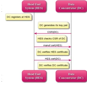
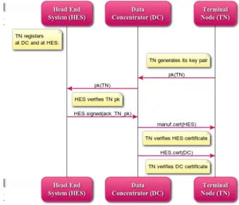
At the latest when installed, a DC generates its key pair and registers at the HES (seeFig. 4), sending its public key in the form of a simple certificate signing request (CSR). The HES checks whether the DC is valid, and if so, returns its own certificate (signed by the manufacturer) and a newly signed certificate for the DC. The DC checks and acknowledges the reception of the certificates.
Fig. 4.DC registers at HES
At the latest when installed, a TN generates its key pair and registers at the DC and at the HES (see Fig. 5), sending its public key DC to the HES. The HES checks if the TN is valid, and if so, returns a signed acknowledgment to the DC. The TN receives from the DC the HES certificate and the DC certificate, and checks them.
Fig. 5.TN registers at DC and at HES
Note that a general public key infrastructure (PKI) is not required because of the simplicity and rather static nature of the scenario. Instead, the required keys and certificates are transmitted in an ad-hoc fashion whenever needed, which is usually when a new node is introduced or replaced. When a DC or TN registers, the assumption is that the CSR or public key of the new node is transmitted authentically (for example, before leaving their protected production environment) or at least the HES can check if the new node is trustworthy by other means (e.g., manual inspection and out-of-band transmission of a key fingerprint or by challenge-response where the public key of the new node is already known to the HES). There is no need for keys to expire, since in case of any failure the respective node may be deactivated and replaced and the new one automatically re-registered in the network.
4.3 Smart Metering and Grid Automation
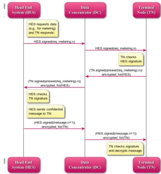
The main use case is that the HES requests metering data and each TN responds (see Fig. 6). Such metering requests are usually sent in multicast/broadcast mode. To ensure authentic requests and prevent replay attacks, the HES signs its request including a sequence number. The TN also signs its response including the same sequence number and encrypts the message in case it includes privacy-critical data.
The polling mechanism for meter readouts employed here may also be used for acquiring grid status information from TNs for grid automation, while on the other hand in most cases status information obtained at the level of DCs is sufficient for grid automation.
The HES may send confidential commands or data to a specific TN, for instance regarding sensitive information on pre-paid accounts of consumers. In this case, messages are not only signed but also encrypted.
Note that the respective DC does not process but just forwards any of these messages in each direction. Consequently, their security is maintained even if the DC is compromised. In other words, correctness and privacy of metering information does not rely on the integrity of the DCs.
Fig. 6.HES requests data; TN responds; HES sends confidential data
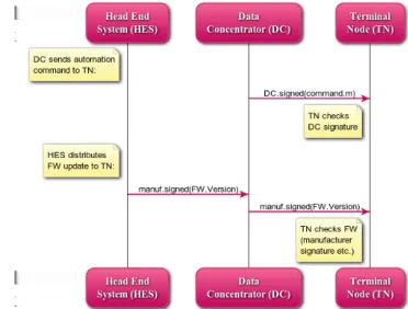
Finally,Fig. 7depicts two further types of messages. Broadcasts of automa-tion commands by a DC to its TNs are signed and replay protected, but do not need to be encrypted since they do not contain confidential data. Administrative messages, for instance firmware updates to the TNs, originating from the HES and relayed by the DCs, are protected in a similar way: the firmware is signed by the manufacturer and includes version information used to prevent version rollback attacks.
4.4 Formal Modeling and Analysis
The model is given in the formal specification language ASLan++ [18]. It de-scribes the general behavior of all parties involved, while the entityLinecaptures a single line between a TN, its DC, and the HES. Two such lines are specified to run in parallel, such that potential interference between them (and of course with an attacker) can be checked.
Fig. 7.DC sends automation command; HES distributes FW update
The security goals per line are given in the goals section and include the authenticity, freshness, and confidentiality properties mentioned above:
authentic_certs_DC: HES and DC certificates received by DCs are authentic. authentic_certs_TN: HES and DC certificates from the HES received by any
TNs are authentic.
fresh_authentic_HES: requests by the HES, sent in broadcast mode to any TNs, are authentic and replay protected.
secure_TN_HES: responses by a TN transmitted to the HES are confidential, authentic, and replay protected.
secure_HES_TN: data from the HES sent in private to a TN are confidential, authentic, and replay protected.
fresh_authentic_DC: automation commands by the DCs, sent in broadcast mode to TNs, are authentic and replay protected.
fresh_authentic_FW: TN firmware updates sent by the HES in broadcast mode are authentic and replay protected.
The AVANTSSAR[2] Tool does not find any attacks on them assuming se-cure cryptographic primitives and local key storage. This result is of interest for two reasons. As witnessed by earlier versions of the model containing mistakes, security goals are easily missed already at the design phase. In particular, au-thentication and freshness flaws are often not obvious. The model demonstrates that a minimal use of cryptography, as long as applied at the right places, is sufficient for achieving all crucial communication security goals.
Note that the analysis of the given model does not regard availability. Still the solution given in this section is better suitable for integrating smart grid functionality than the one summarized in Sec. 2 because it allows for efficient broadcasts/multicasts of time-critical grid automation commands, which require strong authenticity and integrity, but no confidentiality.
5
Concluding Remarks
It may be tempting for parties involved to regard the security of smart metering systems and of grid automation as “business as usual”, since — at a superficial look — they do not appear to provide much specific challenges nor require en-tirely new solutions. Yet the topic does include security pitfalls and turns out to be potentially harmful to the economy [1] and maybe even to the safety of the grid, due to several factors.
Many quite different stakeholders are involved, namely traditional large-scale commodity providers, distribution network operators (utilities), typical consumers, emerging small-scale producers, metering service providers, IT com-ponent developers/providers, and several regulatory and standardization insti-tutions. Most of these parties have no strong background in IT security. This may be one explanation why the smart metering infrastructure rolled out so far in many countries is plainly insecure, and why — even despite of the efforts by various groups involved — in the recent definition of the German regula-tions the mentioned security architecture problems regarding the integration of hardware security modules in smart meter gateways and PKI have not been properly addressed and solved. Moreover, part of the stakeholders have
conflict-ing economic interests, while for an overall solution, they need to co-operate in
non-trivial ways both during the definition and the deployment of smart grid related solutions. This is certainly one of the main reasons for the major delays we are currently experiencing, such that no running large-scale secure solution is in existence these days.
Further, security experts from the classical ICT domain are typically not
familiar with the application domain of commodity networks. Therefore, they
tend to overlook side conditions posed by their physical, organizational, and economic characteristics, for instance communication bandwidth and latency constraints, or the overhead involved in using certain IT infrastructure. Taking these conditions into account may rule out the use of “classical” IT security building blocks such as SSL/TLS. Part of the peculiarities of the smart meter-ing domain have been addressed by the German regulations, for instance the limited computational and communication strength of battery-powered smart meters, while others like the availability and real-time requirements for multi-cast messages needed for grid automation were neglected. Apart from technical side conditions, the economic cost/benefit ratio plays a critical role for the feasi-bility and acceptance of the overall solution, where the development, production, and running costs for security components play is a major factor, in particular for providing certified devices and infrastructure such as PKI.
Even more challenging than smart metering is the grid automation aspect of smart grids. IT security becomes more critical in this setting because attacks on grid control mechanisms may jeopardize the core goals of grid control: safety and availability of the grid. Moreover, it adds a further technical complication, since security tends to be contradictive to availability. Any IT security solution to be used in smart grid applications must carefully consider and support these specific circumstances.
6
Acknowledgments
This work was partially supported by EU-funded project FP7 NESSoS [17] (no. 256980), the FP7-ICT Project SPaCIoS [22] (no. 257876), and the activity TSES 12178 SESSec-EU — “Networked Smart Energy Systems Security in Europe” of the action line “Smart Energy Systems” of the EIT ICT Labs [9].
We are grateful for detailed reviews on this article by Ricarda Weber and Jorge Cu´ellar, as well as further comments by several other colleagues.
A
Formal Security Model in ASLan++
s p e c i f i c a t i o n S m a r t M e t e r i n g c h a n n e l _ m o d e l CCM e n t i t y E n v i r o n m e n t { s y m b o l s manuf , hes : a g e n t ; c e r t i f i c a t e ( agent , agent , p u b l i c _ k e y ): t e x t ; n o n p u b l i c a n s w e r ( t e x t ): t e x t ; msg ( t e x t ): t e x t ; fw ( text , nat ): t e x t ;h e s _ c o u n t e r ( nat ): f a c t ; % g l o b a l for h e a d end s y s t e m
TN1 : a g e n t ; m a c r o s % i m p r o v i n g r e a d a b i l i t y A - > s i g n e d ( M ) = { M } _ i n v ( pk ( A )); % a g e n t A s i g n e d M C - > c e r t ( A ) = C - > s i g n e d ( c e r t i f i c a t e ( C , A , pk ( A ) ) ) ; % a b s t r a c t c e r t i f i c a t e csr ( A ) = A - > s i g n e d ( A . pk ( A )); % a b s t r a c t c e r t i f i c a t e s i g n i n g r e q u e s t M - > e n c r y p t e d _ f o r ( A ) = { M } _pk ( A ); e n t i t y L i n e ( HES , DC , TN : a g e n t ) { s y m b o l s a c k _ T N _ p k : t e x t ; e n t i t y H e a d E n d S y s t e m (Actor, DC , TN : agent , H E S _ c e r t : m e s s a g e ) { s y m b o l s Request , R e s p o n s e : t e x t ; Message , F i r m w a r e : t e x t ; Version , N : nat ; b o d y { % r e g i s t e r a DC s e l e c t{ on(? DC - > A c t o r: csr (? DC ) & ? DC != i & ? DC != m a n u f ): {}} A c t o r - > DC : a u t h e n t i c _ c e r t s _ D C :( a u t h e n t i c _ c e r t s _ T N :( H E S _ c e r t .(Actor- > c e r t ( DC ) ) ) ) ; % r e g i s t e r a TN s e l e c t{on ( DC - > A c t o r: pk (? TN ) & ? TN != i & ? TN != A c t o r): {}} A c t o r - > DC : Actor- > s i g n e d ( a c k _ T N _ p k ); % r e q u e s t ( e . g . , for m e t e r i n g d a t a ) , s e n t by m u l t i c a s t , % and r e s p o n s e R e q u e s t := f r e s h (); r e t r a c t h e s _ c o u n t e r (? N ); A c t o r - > ? : Actor- > s i g n e d ( f r e s h _ a u t h e n t i c _ H E S :( R e q u e s t ). N ); DC - > A c t o r: ( TN - > s i g n e d ( s e c u r e _ T N _ H E S :( a n s w e r (? R e s p o n s e )). N ) ) - > e n c r y p t e d _ f o r (A c t o r); h e s _ c o u n t e r (s u c c( N )); % c o n f i d e n t i a l m e s s a g e M e s s a g e := f r e s h (); r e t r a c t h e s _ c o u n t e r (? N ); A c t o r - > TN : (Actor- > s i g n e d ( s e c u r e _ H E S _ T N :( msg ( M e s s a g e )). N ) ) - > e n c r y p t e d _ f o r ( TN ); h e s _ c o u n t e r (s u c c( N )); % u s i n g m a n u f a c t u r e r key for s i g n e d f i r m w a r e m u l t i c a s t F i r m w a r e := f r e s h (); V e r s i o n := 1; A c t o r - > ?: manuf - > s i g n e d ( f r e s h _ a u t h e n t i c _ F W :( fw ( F i r m w a r e , V e r s i o n ) ) ) ; } }
e n t i t y D a t a C o n c e n t r a t o r ( HES , Actor, TN : a g e n t ) { s y m b o l s H E S _ c e r t , D C _ c e r t : m e s s a g e ; % TN_pk , HES_req , T N _ r s p :: m e s s a g e ; % F W _ u p d a t e : s i g n ( inv ( pk ( a g e n t )) , t e x t . nat ); D C _ c o u n t e r : nat ; C o m m a n d : t e x t ; b o d y { D C _ c o u n t e r := 0; % r e g i s t e r at HES A c t o r - > HES : csr (A c t o r);
HES - > A c t o r: a u t h e n t i c _ c e r t s _ D C :(( manuf - > c e r t ( HES )). ( HES - > c e r t (A c t o r) ) ) ; D C _ c e r t := HES - > c e r t (A c t o r);
% r e g i s t e r a TN
% ? TN - > A c t o r : ? T N _ p k ; A c t o r - > HES : T N _ p k ; % may be short - cut
HES - > A c t o r: HES - > s i g n e d ( a c k _ T N _ p k ); A c t o r - > TN : H E S _ c e r t . D C _ c e r t ;
% r e q u e s t ( for m e t e r i n g d a t a ) , s e n t by m u l t i c a s t , and r e s p o n s e % HES - > A c t o r : ? H E S _ r e q ; A c t o r - > ? : H E S _ r e q ; % may be short - cut % TN - > A c t o r : ? T N _ r s p ; A c t o r - > HES : T N _ r s p ; % may be short - cut
% c o n f i d e n t i a l m e s s a g e
% HES - > A c t o r : ? H E S _ r e q ; A c t o r - > TN : H E S _ r e q ; % may be short - cut % a u t o m a t i o n c o m m a n d to TNs C o m m a n d := f r e s h (); A c t o r - > ?: Actor- > s i g n e d ( f r e s h _ a u t h e n t i c _ D C :( C o m m a n d . D C _ c o u n t e r )); D C _ c o u n t e r := s u c c( D C _ c o u n t e r ); % f i r m w a r e , s e n t by m u l t i c a s t
% HES - > A c t o r : ? F W _ u p d a t e ; Actor - > ?: F W _ u p d a t e ; % may be short - cut
} } e n t i t y T e r m i n a l N o d e ( HES , DC , A c t o r: a g e n t ) { s y m b o l s H E S _ c e r t , D C _ c e r t : m e s s a g e ; R e q u e s t : t e x t ; M e s s a g e : t e x t ; C o m m a n d : t e x t ; H E S _ c o u n t e r , N : nat ; D C _ c o u n t e r : nat ; F i r m w a r e : t e x t ; V e r s i o n : nat ; n o n p u b l i c s e e n _ V e r s i o n s : nat set ; L o o p C o u n t : nat ; b o d y { H E S _ c o u n t e r := 0; D C _ c o u n t e r := 0; % r e g i s t e r at DC A c t o r - > DC : pk (A c t o r); s e l e c t { on( DC - > A c t o r: a u t h e n t i c _ c e r t s _ T N :(? H E S _ c e r t .? D C _ c e r t ) & ? H E S _ c e r t = manuf - > c e r t (? HES ) &
? D C _ c e r t = ? HES - > c e r t ( DC )): {} } % l i m i t l o o p to 4 r o u n d s w h i l e ( L o o p C o u n t != s u c c(s u c c(s u c c(s u c c( ? ) ) ) ) ) { s e l e c t { % r e q u e s t ( for m e t e r i n g d a t a ) , s e n t by m u l t i c a s t , and r e s p o n s e on( DC - > A c t o r: HES - > s i g n e d ( f r e s h _ a u t h e n t i c _ H E S :( ? R e q u e s t ).? N ) & (? N = H E S _ c o u n t e r | ? N = s u c c( H E S _ c o u n t e r ) | ? N = s u c c(s u c c( H E S _ c o u n t e r ) ) ) ) : { % N >= T C _ C o u n t e r A c t o r - > DC : (Actor- > s i g n e d ( s e c u r e _ T N _ H E S :( a n s w e r ( R e q u e s t )). H E S _ c o u n t e r )) - > e n c r y p t e d _ f o r ( HES ); H E S _ c o u n t e r := s u c c( N ); } % c o n f i d e n t i a l m e s s a g e % H E S _ c o u n t e r s h o u l d be g r e a t e r t h a n b e f o r e on( DC - > A c t o r: ( HES - > s i g n e d ( s e c u r e _ H E S _ T N :( msg (? M e s s a g e )). H E S _ c o u n t e r )) - > e n c r y p t e d _ f o r (A c t o r)): { H E S _ c o u n t e r := s u c c( H E S _ c o u n t e r ); }
% a u t o m a t i o n c o m m a n d on( DC - > A c t o r: DC - > s i g n e d ( f r e s h _ a u t h e n t i c _ D C :(? C o m m a n d . D C _ c o u n t e r ) ) ) : { D C _ c o u n t e r := s u c c( D C _ c o u n t e r ); } % f i r m w a r e , s e n t by m u l t i c a s t on( HES - > A c t o r: manuf - > s i g n e d ( f r e s h _ a u t h e n t i c _ F W :( fw (? F i r m w a r e ,? V e r s i o n ))) & ! s e e n _ V e r s i o n s - > c o n t a i n s (? V e r s i o n )): { s e e n _ V e r s i o n s - > add ( V e r s i o n ); } } L o o p C o u n t := s u c c( L o o p C o u n t ); } } } b o d y { % of L i n e
new H e a d E n d S y s t e m ( HES , DC , TN , manuf - > c e r t ( HES )); new D a t a C o n c e n t r a t o r ( HES , DC , TN ); new T e r m i n a l N o d e ( HES , DC , TN ); } g o a l s a u t h e n t i c _ c e r t s _ D C :( _ ) HES * - > DC ; a u t h e n t i c _ c e r t s _ T N :( _ ) HES * - >? ?; f r e s h _ a u t h e n t i c _ H E S :( _ ) HES * - > >? ?; s e c u r e _ T N _ H E S :( _ ) TN * - > >* HES ; s e c u r e _ H E S _ T N :( _ ) HES * - > >* TN ; f r e s h _ a u t h e n t i c _ D C :( _ ) DC * - > >? ?; f r e s h _ a u t h e n t i c _ F W :( _ ) HES * - > >? ?; } b o d y { % of E n v i r o n m e n t h e s _ c o u n t e r ( 0 ) ;
any DC . L i n e ( hes , DC , TN1 ) w h e r e hes != DC & DC != TN1 & TN1 != hes ; any DC TN2 . L i n e ( hes , DC , TN2 ) w h e r e hes != DC & DC != TN2 & TN2 != hes
& TN2 != TN1 ; % p r e v e n t d u p l i c a t e i n s t a n c e s of s a m e T e r m i n a l N o d e TN
} }
References
1. Anderson, R., Fuloria, S.: On the security economics of electricity metering.
Workshop on the Economics of Information Security, WEIS (June 2010), http:
//weis2010.econinfosec.org/papers/session5/weis2010_anderson_r.pdf 2. AVANTSSAR: Automated VAlidatioN of Trust and Security of Service-oriented
ARchitectures (2008–2010),http://avantssar.eu
3. BSI: Federal Office for Information Security, Bonn, Germany,https://www.bsi.
bund.de/EN/
4. BSI: Protection Profile for the Gateway of a Smart Metering System (December
2012), https://www.bsi.bund.de/SharedDocs/Downloads/DE/BSI/SmartMeter/
PP-SmartMeter.pdf
5. BSI: Protection Profile for the Security Module of a Smart Meter
Gate-way (December 2012), https://www.bsi.bund.de/SharedDocs/Downloads/DE/
BSI/SmartMeter/PP_Security_%20Module.pdf
6. BSI: TR-03109 Smart Energy (2012), https://www.bsi.bund.de/DE/Themen/
SmartMeter/TechnRichtlinie/TR_node.html
7. CC: Common Criteria for Information Technology Security Evaluation, ISO/IEC
15408. http://www.commoncriteriaportal.org/
8. Continental Automotive GmbH: Digital Tachograph DTCO 1381,
Re-lease 2.0 (June 2012), https://www.bsi.bund.de/SharedDocs/Zertifikate/CC/
Digitaler_Tachograph-Vehicle_Unit/0559.html
9. EIT ICT Labs: Smart energy systems, http://www.eitictlabs.eu/
10. Energie-Control Austria, Vienna: Intelligente Messger¨
ate-Anforderungs-Verordnung IMA-VO (November 2011), http://www.ris.bka.gv.at/
GeltendeFassung.wxe?Abfrage=Bundesnormen&Gesetzesnummer=20007497 11. Fries, S., Falk, R., Sutor, A.: Smart grid information exchange — securing the
smart grid from the ground. In: Cu´ellar, J. (ed.) SmartGridSec 2012. LNCS, vol.
7823, pp. 25-43. Springer, Heidelberg (2013)
12. Jehle, C.: Rohrkrepierer Intelligenter Stromz¨ahler? Telepolis online magazine,
Heise Zeitschriften Verlag (2012), http://www.heise.de/tp/artikel/38/38139/
1.html
13. Klimke, M., Shire, C., Klimke, Technologies, I.: Smart Grid cyber
at-tacks – Germany steps up the protection (September 2011), http:
//silicontrust.wordpress.com/2011/09/23/smart-grid-cyber-attacks-% E2%80%93-germany-steps-up-the-protection/
14. Krebs, B.: FBI: smart meter hacks likely to spread (April 2012), http://
krebsonsecurity.com/2012/04/fbi-smart-meter-hacks-likely-to-spread/
15. Marlinspike, M.: SSL and the future of authenticity (August 2011),
Talk held at Black Hat 2011. http://www.thoughtcrime.org/blog/
ssl-and-the-future-of-authenticity/
16. Merkle, R.C.: A digital signature based on a conventional encryption function. In: Pomerance, C. (ed.) CRYPTO 1987. LNCS, vol. 293, pp. 369–378, Springer, Heidelberg (1988)
17. NESSoS: Network of Excellence on Engineering Secure Future Internet Software
Services and Systems (2010–2014),http://www.nessos-project.eu/
18. von Oheimb, D., M¨odersheim, S.: ASLan++ — a formal security specification
language for distributed systems. In: Aichernig, B., de Boer, F., Bonsangue, M.M.
(eds.) FMCO 2010. LNCS, vol. 6957, pp. 1–22, Springer, Heidelberg (2011),http:
//ddvo.net/papers/FMCO2010.html
19. Open Smart Grid User’s Group: Advanced Metering Infrastructure Security,http:
//osgug.ucaiug.org/utilisec/amisec/
20. Paverd, A.J., Martin, A.P.: Hardware security for device authentication in the
Smart Grid. In: Cu´ellar, J. (ed.) SmartGridSec 2012. LNCS, vol. 7823, pp. 71-83.
Springer, Heidelberg (2013)
21. Petrlic, R.: A privacy-preserving concept for smart grids. In: Sicherheit in ver-netzten Systemen: 18. DFN Workshop, pp. B1–B14. Books on Demand GmbH (2010)
22. SPaCIoS: Secure Provision and Consumption in the Internet of Services. http:
//spacios.eu/(2010–2013)
23. Task force on Smart Grid privacy and security of the Smart Meters Coordination Group: Privacy and Security approach. Version 0.9 (November 2012)
24. Trusted Computing Group: Trusted Platform Module (TPM), http://www.
trustedcomputinggroup.org/developers/trusted_platform_module