Air Force Institute of Technology Air Force Institute of Technology
AFIT Scholar
AFIT Scholar
Theses and Dissertations Student Graduate Works
9-10-2010
Accelerating Malware Detection via a Graphics Processing Unit
Accelerating Malware Detection via a Graphics Processing Unit
Nicholas S. KovachFollow this and additional works at: https://scholar.afit.edu/etd
Part of the Graphics and Human Computer Interfaces Commons, and the Information Security Commons
Recommended Citation Recommended Citation
Kovach, Nicholas S., "Accelerating Malware Detection via a Graphics Processing Unit" (2010). Theses and Dissertations. 1989.
https://scholar.afit.edu/etd/1989
Accelerating Malware Detection via a
Graphics Processing Unit THESIS
Nicholas S. Kovach, Civ AFIT/GCO/ENG/10-12
DEPARTMENT OF THE AIR FORCE AIR UNIVERSITY
AIR FORCE INSTITUTE OF TECHNOLOGY
Wright-Patterson Air Force Base, Ohio
The views expressed in this thesis are those of the author and do not reflect the official policy or position of the United States Air Force, Department of Defense, or the United States Government.
AFIT/GCO/ENG/10-12
Accelerating Malware Detection
via a
Graphics Processing Unit
THESIS
Presented to the Faculty
Department of Electrical and Computer Engineering Graduate School of Engineering and Management
Air Force Institute of Technology Air University
Air Education and Training Command In Partial Fulfillment of the Requirements for the
Degree of Master of Science
Nicholas S. Kovach, BSCS Civ
September 2010
AFIT/GCO/ENG/10-12
Abstract
Real-time malware analysis requires processing large amounts of data storage to look for suspicious files. This is a time consuming process that (requires a large amount of processing power) often affecting other applications running on a personal computer. This research investigates the viability of using Graphic Processing Units (GPUs), present in many personal computers, to distribute the workload normally precessed by the standard Central Processing Unit (CPU).
Three experiments are conducted using an inductry standard GPU, the NVIDIA GeForce 9500 GT card. The goal of the first experiment is to find the optimal number of threads per block for calculating MD5 file hash. The goal of the second experiment is to find the optimal number of threads per block for searching an MD5 hash database for matches. In the third experiment, the size of the executable, executable type (be-nign or malicious), and processing hardware are varied in a full factorial experimental design. The experiment records if the file is benign or malicious and measure the time required to identify the executable. This information can be used to analyze the performance of GPU hardware against CPU hardware.
Experimental results show that a GPU can calculate a MD5 signature hash and scan a database of malicious signatures 82% faster then a CPU for files between 0 -96 kB. If the file size is increased to 97 - 192 kB the GPU is 85% faster than the CPU. This demonstrates that the GPU can provide a greater performance increase over a CPU. These results could help achieve faster anti-malware products, faster network intrusion detection system response times, and faster firewall applications.
Acknowledgements
I would like to thank my advisor, Dr. Barry Mullins, for the support and encouragement to follow my ideas. I would also like to thank Dr. Michael Grimaila and Dr. Gilbert Peterson for their support and feedback.
I owe a special thank you to Ali and Teigan for being supportive and under-standing throughout the course of this thesis effort.
Table of Contents
Page Abstract . . . iv Acknowledgements . . . vi List of Figures . . . ix List of Tables . . . x List of Abbreviations . . . xi I. Introduction . . . 1 1.1 Motivation . . . 11.2 Overview and Goals . . . 2
1.3 Thesis Layout . . . 3
II. Literature Review and Related Research . . . 4
2.1 Portable Executable Files . . . 4
2.2 Static Malware Detection . . . 7
2.3 MD5 . . . 11
2.4 Intel Pentium 4 (CPU) . . . 13
2.5 PCI Express 2.0 . . . 14
2.6 Graphical Processing Unit (GPU) . . . 16
2.6.1 NVIDIA GPU Basics . . . 17
2.6.2 CUDA by NVIDIA . . . 23 2.6.3 GeForce 9500 GT . . . 29 2.7 ClamAV Engine . . . 30 2.8 Related Work . . . 31 2.9 Summary . . . 35 III. Methodology . . . 36
3.1 Goals and Hypothesis . . . 36
3.2 Approach . . . 38
3.2.1 Software . . . 38
3.2.2 Malicious and Benign Files . . . 39
3.2.3 Signature Databases . . . 40
3.2.4 GPU ID Algorithm . . . 41
3.3 System Boundaries . . . 41
Page 3.5 Workload . . . 44 3.6 Performance Metrics . . . 44 3.6.1 Identification Result . . . 44 3.6.2 Execution Time . . . 44 3.7 System Parameters . . . 45 3.8 Factors . . . 45 3.9 Evaluation Technique . . . 46 3.10 Experimental Design . . . 49 3.10.1 Experiment 1 . . . 49 3.10.2 Experiment 2 . . . 49 3.10.3 Experiment 3 . . . 50 3.11 Methodology Summary . . . 50
IV. Results and Analysis . . . 51
4.1 Results and Analysis of Experiment 1 . . . 51
4.2 Results and Analysis of Experiment 2 . . . 53
4.3 Results and Analysis of Experiment 3 . . . 55
4.4 Overall Analysis . . . 59
4.5 Summary . . . 60
V. Conclusions . . . 61
5.1 Conclusions of Research . . . 61
5.1.1 Goal #1: Correctly Detect Malicious and Benign File Using Predetermined Signatures. . . 61
5.1.2 Goal #2: Measure the Performance of a GPU. . 61
5.1.3 Goal #3: Find the Optimal Number of Threads per Block . . . 62
5.2 Significance of Research . . . 62
5.3 Recommendations for Future Research . . . 63
VI. Experimental Data . . . 65
6.1 Experimental Data of Experiment 1 . . . 65
6.2 Experimental Data of Experiment 2 . . . 70
6.3 Experimental Data of Experiment 3 . . . 75
Bibliography . . . 78
List of Figures
Figure Page
2.1. Overview of the PE File Format Structure [Pie94] [Pie02] [Szo05]. 5
2.2. Overview of a PE File in Memory [Pie02]. . . 7
2.3. Malware Protection Process. . . 9
2.4. MD5 Operation [Riv92]. . . 13
2.5. PCI Express in a Hypothetical System. . . 15
2.6. CPU and GPU similarities [NVI09b]. . . 16
2.7. CUDA Grid, Thread Blocks, and Threads [NVI09b]. . . 18
2.8. CUDA Example Code: Thread Divergence. . . 19
2.9. Overview of Visible Memory under CUDA [NVI09b]. . . 21
2.10. CUDA Nvcc Paradigm [NVI09b]. . . 25
2.11. CUDA Software Stack [NVI09b]. . . 27
3.1. Overview of the GPU ID System . . . 39
3.2. Overview of the GPU ID System Implementation on a CPU. . 40
3.3. The GPU ID System. . . 42
3.4. Component Under Test (CUT). . . 42
4.1. Mean MD5 hash times for 1 - 256 threads per block on a GPU. 53 4.2. Mean database search times and confidence intervals for 256 -512 threads per block on a GPU. . . 55
List of Tables
Table Page
2.1. CUDA Memory Characteristics [NVI09c] [NVI09b]. . . 21
2.2. CUDA Driver API Objects [NVI09b]. . . 28
2.3. XFX 9500 GT Hardware Specifications [XFX09]. . . 30
2.4. CUDA Memory Characteristics. . . 30
2.5. ClamAV Databases with Purpose and Signature Format [Cla09b]. 32 3.1. Graphic Processing Unit IDentifier Experiment Summary. . . . 37
3.2. Factors and Associated Levels for Experiments 1 and 2. . . 46
3.3. Factors and Associated Levels for Experiment 3. . . 47
3.4. PC Specification Overview. . . 48
3.5. GeForce 9500 GT Specification Overview. . . 48
4.1. Probability of Correctly Identifying Files. . . 56
4.2. GPU ID Times (ms). . . 56
4.3. CPU Implementation Times (ms). . . 57
4.4. Hypothesis Testing on Performance of the CPU. . . 58
4.5. Percentage Change of Configurations of a GPU from a CPU. . 59
F.1 Optimal Number of Threads Per Block forExperiment 1. . . 70
F.2 Optimal Number of Threads Per Block forExperiment 2. . . 75
List of Abbreviations
Abbreviation Page
CPU Central Processing Unit . . . 1
GPU Graphics Processing Unit . . . 1
GPU ID Graphic Processing Unit IDentifier . . . 2
PC Personal Computer . . . 2
GPGPU General Purpose Graphics Processing Unit . . . 4
GPU Graphics Processing Unit . . . 4
PE Portable Executable . . . 4
COFF Common Object File Format . . . 4
CPU Central Processing Unit . . . 4
OS Operating System . . . 6
RVA Relative Virtual Address . . . 6
DLL Dynamically Loaded Library . . . 6
IAT Import Address Table . . . 6
MD5 Message Digest 5 . . . 9
RFC Request for Comments . . . 12
ASCII American Standard Code for Information Interchange . . . 13
L1 Level 1 . . . 13
MB Megabyte . . . 13
L2 Level 2 . . . 13
SSE2 Streaming SIMD Extensions 2 . . . 13
SSE3 Streaming SIMD Extensions 3 . . . 13
HT Hyper-Threading . . . 13
BIOS Basic Input/Output System . . . 14
PCIe PCI Express . . . 14
Abbreviation Page
TLPs Transaction Layer Packets . . . 15
SIMD Single-Instruction Multiple-Data . . . 17
SIMT Single Instruction Multiple Thread . . . 17
SPMD Single Program Multiple Data . . . 17
MIMD Multiple Instructions Multiple Data . . . 17
DRAM Dynamic Random Access Memory . . . 22
CUDA Compute Unified Device Architecture . . . 23
API Application Programming Interface . . . 24
PTX Parallel Thread Execution . . . 24
GF GeForce . . . 48
Accelerating Malware Detection
via a
Graphics Processing Unit
I. Introduction
1.1 Motivation
Everyday, data are created, collected, stored, searched, and replicated. As the amount of data grows, so does the time required to detect data that has been infected by malicious worms, viruses, trojans, spyware, and adware. Due to the large amount of time required to scan files and compare them to a database of known signatures, the user will experience a decrease in the responsiveness of their PC. As a result, they may disable the protection application such as Symantec Anti-virus [Vak10] or McAfee Anti-virus [McA09]. If the product is disabled, then the user is not protected against known malicious threats. Slow scanning times also mean that the malicious code, if executed, has more time to hide or infect other files in the system.
To help reduce the large amount of Central Processing Unit (CPU) resources anti-virus products need, the goal of this research is to offload part of the scanning and searching for signature matches to a mainstream Graphics Processing Unit (GPU). Most applications do not take advantage of GPUs for non-graphical tasks, even though they are openly available for all newer computers [NVI09b] and are often not fully utilized by the average computer user [ViG07]. The system developed in this research is designed to use the unused power of the GPU by reducing CPU resource demand and increase system security by allowing the file scanning to complete without the user noticing. Because only one video card driver can be loaded by Windows XP, the GPU was still responsible for displaying graphics on a terminal, but the monitor was turned off during the experiments to minimize the impact of graphical display
then memory on the GPU could be modified to support the display and cause any application running on the GPU to return an error.
GPUs at one time were only available to handle graphics. Over time they have evolved into a general purpose GPU, allowing code to be written and directly executed on the GPU. This allows applications to directly use the GPU to offload computational tasks without consuming resources of the CPU.
1.2 Overview and Goals
This research focuses on the design and analysis of a malware detection tool, called Graphic Processing Unit IDentifier (GPU ID), that uses the parallel power of the GPU to scan files by calculating a MD5 file hash and then searching a database of signatures from malicious files. The GPU ID system is designed to be used on a per-sonal computer (PC) but may be expanded to gateway monitoring systems. For each file, the GPU ID system calculates a MD5 file hash and then searches the malware signature database. If the hash is in the database then the file is considered mali-cious, otherwise the file is considered benign. The calculated MD5 hashes are never transfered back to the CPU from the GPU device. Instead a set of flags indicating the malicious status of each file is transfered to the CPU and the user is alerted to files that match a database entry.
There are three goals for this research. The first goal is to find the optimal number of threads per block for calculating MD5 file hashes. To accomplish this goal a GeForce 9500 GT GPU is used to calculate MD5 file hashes, while the number of threads per block is varied. The second goal is to find the optimal number of threads per block for searching a MD5 signature database for hash matches. To accomplish this goal the Clam AV [Cla09a] MD5 signature database is used and modified, and a GeForce 9500 GT GPU is used to calculate MD5 file hashes and search the signature database, while the number of threads per block is varied only for the search part of the program. The third goal is to measure the performance of a GPU while detecting malware. To accomplish this goal the time to calculate MD5 file hashes and search
the signature database are measured for groups of files and then compared to the times required for a CPU to complete the same task.
1.3 Thesis Layout
This chapter introduces the research topic, provides the motivation, and outlines the goals of the research. Chapter 2 provides background information on Portable Executable (PE) Files, static malware detection, the MD5 algorithm, CUDA GPU basics, and the GeForce 9500 GT GPU. The methodology used to develop, set up, configure, and conduct the experiment to test the performance of the GPU is out-lined in Chapter 3. The experimental results are presented and analysis in Chapter 4. Chapter 5 provides a discussion of the conclusions drawn from the experimental results, the significance of the GPU ID system, and possible areas for future research. Appendix VI contains the raw data collected during the experiment.
II. Literature Review and Related Research
T
his chapter describes the background and related work for detecting malware with a GPGPU, referred to hereafter as GPU. Background is provided in Sec-tions 2.1 through 2.7. SecSec-tions 2.1 through 2.3 provide background on PE files, static malware detection, and MD5 fingerprinting. Section 2.4 provides a detailed overview of the Intel Pentium Architecture, and Section 2.5 provides an overview of the PCI Express 2.0 I/O bus architecture. The NVIDIA GPU and CUDA architectures are discussed in Section 2.6, followed by Section 2.7 with an overview of Clam AV anti-virus components. Section 2.8 discusses related work with GPU malware detection.2.1 Portable Executable Files
The Portable Executable (PE) file format is designed for use on all Microsoft Win32 operating systems. The format defines the structure of the executable file data and how the file data is interpreted. The PE file format is expected to remain part of Microsoft’s operating systems for the future [Szo05]. The PE format is an updated version of the common object file format (COFF) [Mic06]. Microsoft released a new format PE+, or PE32+, for use on Win64 operating systems with the release of Windows XP 64-bit [Mic08]. The PE+ format is similar to the PE format except for modification to support 64-bit operating systems.
As shown in Figure 2.1, a PE file is composed of many components. The first component is an MS-DOS header and stub program. The stub program displays an error message, “This program cannot be run in MS-DOS mode” [Pie94]. The stub program provides compatibility for 16-bit Windows systems by not allowing the file to be executed in DOS [Szo05]. The second component, after the MS-DOS header and stub program, is the PE header, which starts with the constant of ‘PE00’ [Pie02]. The PE header contains information about the intended type of CPU, number of sections, characteristics, size of image, and the checksum of the PE file.
Between the headers and raw data of the sections is the section table. The section table contains a header for each section in the PE file. The section header
MS-DOS MZ Header .text Section Header PE File Optional Header
PE File Header "PE" File Signature MS-DOS Stub Program
.edata Section
.debug Section Header :
:
.rsrc Section Header
.data Section Header .text Section .debug Section
.rsrc Section
.data Section .idata Section
.edata Section Header .idata Section Header .reloc Section Header
.reloc Section Higher offsets Section Table PE File : :
Figure 2.1: Overview of the PE File Format Structure [Pie94] [Pie02] [Szo05].
contains the name, size, address information and attributes for the section. The Microsoft Windows’ memory manger will use the information in the section header to determine if the section is readable, writable, or executable [Eil05].
Common PE file sections include: .text, .data, .bss, .rsrc, .idata, .edata, .reloc, and .debug. The .text section contains the actual executable code and is normally the first section in a PE file [Szo05]. The PE file format is designed to allow executable
writable flag is not set because data is kept in the .data section, so there is no need to write to the .text section. This helps to keep the running program from overwriting code instructions. Data is stored in the .data section and the .bss section. The .data section contains initialized data, while the .bss section contains uninitialized static and global variables. Resources, such as images, menus, default initialization strings, etc., for the application are stored in the .rsrc section. The import table, containing a list of functions used from external libraries, is located in the .idata section, and functions exported for use by other applications are located in the .edata section. The PE format defines a .reloc section containing a base relocation table; this section has been removed from Windows 9x and later operating systems by Microsoft [Szo05]. Any debug information about the executable is located in the .debug section. This information is optional and may not be present in all PE executables because including it will increase the size of the executable.
The structure of a PE file loaded into memory looks similar to the PE file on a disk [Szo05]. Figure 2.2 shows the structure of a PE file mapped into memory. The headers and section layout remain the same, but the individual sections are page-aligned in memory. This allows the OS to assign different access permissions to the resulting pages. Sections are not page aligned on disk to avoid wasting disk space [Pie02]. When a PE file is compiled, all addresses are compiled to a fixed base memory address. The OS will try to load the PE file to this memory address, but if the address is not available the OS will choose another address. To avoid having fixed memory addresses in PE files that need to be updated if the OS cannot load the file into the fixed base memory address, Relative Virtual Addresses (RVA) are used. A RVA is just an offset in memory, which when added to the address where the PE file was actually loaded by the OS, gives the actual memory address needed by the executable code in the PE file [Pie02].
Function calls to Dynamically Loaded Libraries (DLL) are handled by the Im-port Address Table (IAT). The IAT contains a list of all functions (symbols) and the respective memory address for the function being imported by the application. When
MS-DOS MZ Header Section Table PE File Optional Header
PE File Header "PE" File Signature MS-DOS Stub Program
Other Sections .text Section .debug Section .data Section .reloc Section Higher offsets PE File MS-DOS Header .data Section .text Section Section Table PE Header Other Sections Higher addresses In Memory
Figure 2.2: Overview of a PE File in Memory [Pie02].
the PE file is loaded into memory, the memory addresses are overwritten with the actual memory addresses of the symbols by the system loader [Mic08]. This memory address represents the address that is invoked when a call is made to imported func-tions [Pie02]. Since the PE file is mapped into linear address space, the application only knows the base address of where the executable was mapped into memory. By using the IAT, only the IAT has to be updated instead of the individual function calls within the executable [Szo05].
2.2 Static Malware Detection
Signature-based detection methods of malware have long been used by commer-cial anti-virus software. This type of detection method has been used since the late 1980’s with only optimizations and improvements in algorithms since then [For04]. Commercial anti-virus software is commonly used to protect home and business com-puting systems from malware or unwanted programs. Generally, signature detection
involves the inspection of files (usually executables) on digital storage mediums for predefined signatures [Kel09]. Recently, other file formats such as DOC, PPT, XLS, and PDF have been used to carry malware and are also inspected by commercial anti-virus software [MIT07] [MIT09b] [MIT09a].
Signatures are generated based on the composition or attribute(s) of a partic-ular piece of malware, so the signatures are unique to that piece of malware [For04]. Signatures are generated based on either the whole file or individual code strings of the file, which signify malware behavior by applying a hashing algorithm to the file or individual sections of the file [Hey07]. In the case of PE files, the sections are identi-fied by the information in the section table of the PE file. The predefined signature is then compared to live signatures generated by the anti-virus software tool, using the same hashing algorithm in real time. If there is a match, then file execution access on the intended machine is blocked, the file is deleted, or the user is alerted [Hey07]. This process is known as black listing.
Black listing may be reversed for trusted files in a process known as white listing. The signatures are still generated based on the file or individual code strings of the file, but if the on-the-fly and predefined signatures match, then file execution access is granted to the intended machine, otherwise the file execution is blocked [McA09]. White listing provides more protection than black listing, but decreases usability of the intended machine because the user no longer chooses which applications to trust. Another version of white listing involves signing the executable and then allowing only executables digitally signed by a trusted party to be executed. This technique is used in Microsoft Windows Operating Systems (XP, Vista, and Windows 7) to verify certified system drivers [Mic07a].
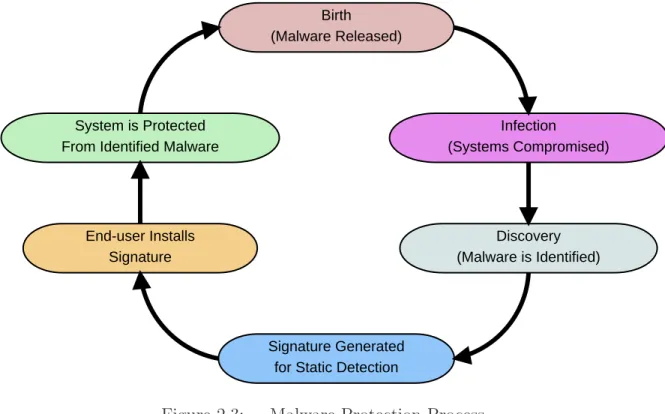
Malware may use a combination of methods to hide itself from signature-based detection software. Such methods include: altering the source code, using a packer, obfuscation, and editing the executable code [Kel09]. Each time one of these methods is used by the malware, a new signature must be generated and installed in the
Birth (Malware Released) Infection (Systems Compromised) Discovery (Malware is Identified) Signature Generated for Static Detection End-user Installs
Signature System is Protected From Identified Malware
Figure 2.3: Malware Protection Process.
signature-based detection software, requiring interaction by the user or the system to be connected to a network to access the update server to automatically install the new signatures. This is in addition to the time required to discover the modified malware and generate a new signature. Figure 2.3 shows the process of protecting a system with static detection. Once the malware is released in the wild, it must infect, or compromise, vulnerable systems. A compromised system or Honeypot then discovers the malware and submits it for analysis. After analysis, a signature is generated. This signature must be installed by the user before the system is protected.
Hash algorithms, such as MD5 [Riv92], are often used to create signatures of malware [Cla09b]. The hash algorithm produces a shorter representation of the file or file attributes into a fixed length fingerprint. The fixed length fingerprint is then used as the signature. In order to be used in fingerprinting the hash algorithm is required to produce large changes in the hash result for small changes in the file or file attributes. Using hashes to fingerprint files is not always infallible.
False positives occur when a file is identified as malicious when it really contains benign code [Vak10]. Anti-virus scanners, using static detection techniques, may give a large amount of false positive alerts [NAs02]. These alerts can be costly in terms of time and resources for individuals and organizations to investigate each misidentified file [YWL07] [Vak10]. False positives are possible, since the hashes used as fingerprints are a fixed length and the number of possible strings is infinite. According to the Pigeon Hole Principle, because the number of fingerprints is less than the number of possible strings, multiple strings will be represented by the same fingerprint. False positives can be reduced by using specific signatures [Szo05], such as generating the fingerprint by calculating the file hash of the malicious file. This would reduce the number of false positives, but may increase the number of false negatives (discussed later), in the case where the malicious file varies slightly from one instance to the next [Pau08]. A recent example of a false positive is when a signature in a McAfee anti-virus product identified the core Windows XP binary svchost.exe as a anti-virus crippling the operating system [McA10].
False negatives occur when a file is identified as benign when it really con-tains malicious code [Pau08]. This happens when a signature is missing from the virus database. This is possible for new malware or in cases where the database is outdated (i.e., the user does not regularly update the database to learn about new viruses). In order for static detection to be useful the malware must first be an-alyzed, a signature generated, and then the signature must be added to the users database. Here, the initial detection of the malware is required for the signature to be generated. Without the initial detection, anti-virus protection would be difficult or impossible [Coh86] [Coh87]. False negatives can be reduced by using generic signa-tures [Szo05]. A generic signature may be generated by basing the hash fingerprint on several malicious attributes shared by similar malicious software, if these attributes are found when scanning then there is a chance the file is malicious. Generic signatures have the side-effect of increasing false positives.
Using a combination of false positive and false negative reduction techniques lowers the chances of unwanted alerts (false positives) and infections (false negatives) [NAs02]. In addition, white listing of critical system files reduces the chance of one being identified as malicious.
2.3 MD5
The MD5 message digest algorithm was developed by Ronald Rivest in 1992 [Riv92]. It was developed for applications where a sequence of bytes, message, file, or other data must be represented by a small fixed length identifier. MD5 takes in a piece of data, of an arbitrary length, and outputs a 128-bit message digest. The algorithm is designed to be: easy to compute the digest; hard to compute the message from the digest; and hard to find two messages with the same digest [StL07]. Although it is known that many attacks exist on the MD5 algorithm to produce collisions [XiH05] [YJD09] or two messages with the same digest, it still provides a useful method for fingerprinting a sequence of bytes or files.
The MD5 algorithm starts by padding the raw data until its length is congruent to 448, modulo 512. A single ’1’ bit followed by enough ’0’ bits are used in the padding. At least one bit, is appended and at most 512 bits are appended to the raw data. Next, the length of the data before padding is appended to the end of the padded result. The length is represented as two bytes with the lower order byte added first. If the length of the data exceeds 264, then only the low-order 64 bits of
the length are appended. Four 32-bit registers are initialized to the following constant initialization values in hexadecimal with low-order bytes first [Riv92]:
GA = 01 23 45 67
GB = 89 ab cd ef
GC = fe dc ba 98
Four functions map three of the 32-bit registers to one 32-bit register. The functions are as follows [Riv92]:
F(B, C, D) = (B∧C)∨(¬B∧D) G(B, C, D) = (B∧D)∨C¬D
H(B, C, D) = B ⊗C⊗D
I(B, C, D) = C⊗(B∨ ¬D)
The data, message (M), is processed by the MD5 algorithm in 512-bit (64-byte) chunks. One MD5 operation is completed for each byte. An MD5 operation is shown in Figure 2.4 and starts with the local registers A, B, C, and D being initialized with the values from the global registers GA, GB, GC, and GD. For each byte (represented by [i]) of the 64 bytes in the chunk, a function from above is selected during each operation. For bytes 0 15 function F is used, bytes 16 31 function G, bytes 32 -47 function H, and bytes 48-63 function I. Each function takes registers B, C, and D as inputs. A fixed constant K is added to the byte from the message, the constant for each byte in a chunk is listed in RFC 1321 [Riv92]. A left shift (<<s) is also applied; the amount of the shifts are listed in RFC 1321 as well. The registers are then updated as follows:
temp (register)= D D = C
C = B
B = B + (A + function(B,C,D) + k[i] + M[i])<<s[i] A = temp
After all 64 bytes have been processed, the results in A, B, C, D and are added to the results from previous 64-byte chunks and stored in registers GA, GB, GC, GD (i.e., GA = GA + A, GB = GB + B, etc.). The message is processed in this manner until there are no more chunks left. The MD5 digest output is from the registers
<<s F,G, H or I A B C D A B C D Ki Mi
denotes addition modulo 232
Figure 2.4: MD5 Operation [Riv92].
GA, GB, GC, GD in alphabetical order. The digest output is often converted to a 32 character ASCII hexadecimal value for readability. The small 32 character ASCII value represents a large file, making MD5 a good algorithm for fingerprinting files in malware detection.
2.4 Intel Pentium 4 (CPU)
The Intel Pentium 4 processor, or central processing unit (CPU), is manufac-tured using Intel’s 90nm process supporting speeds of 2.40 - 2.80 GHz [Int05]. The processor has 16 KB of Level 1 (L1) data cache and 1 MB of Level 2 (L2) cache. The processor has a front side bus of 800 MHz, with support for Streaming SIMD Ex-tensions 2 (SSE2) and Streaming SIMD ExEx-tensions 3(SSE3). SSE2 defines hardware instructions for 64-bit floating point operations [Int00], while SSE3 defines hardware instructions for thread management [Int08].
The Pentium 4 supports Hyper-Threading (HT) technology which allows a single physical processor to function as two logical processors [Int05]. Each logical proces-sor has its own control registers, while sharing caches, execution units, and buses.
HT technology is designed to use processor resources more efficiently and improve performance of multi-threaded software [Int10a]. To use HT on the Pentium 4, a HT-enabled BIOS and operating system such as Microsoft Windows XP or newer is required.
The Pentium 4 was selected for this research because of its availability and abil-ity to run common operating systems, such as Windows XP [Mic01], Vista [Mic07b], Windows 7 [Mic10], and many distributions of Linux [Ubu10] [Dam10] [Pup09]. The Hyper-Threading technology is enabled on the Pentium 4 to use system resources more efficiently.
2.5 PCI Express 2.0
The latest NVIDIA GPUs, including the GeForce 9500 GT, connect to the motherboard through a PCI Express 2.0 (PCIe) bus. PCIe is a third generation high performance I/O bus designed for high bandwidth peripherals (end points), such as video controllers, memory, and disk drives [BAS04]. The bus is implemented as a serial point-to-point architecture allowing communication between two PCIe devices [BAS04]. PCIe supports data rates of 128 Gbit/sec [Int10b].
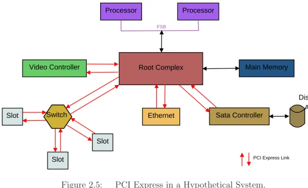
The PCIe fabric is comprised of a root complex, any number of switches, and any number of endpoints. The root complex connects CPUs and memory subsystem to the PCIe fabric. PCIe switches forward packets between endpoints and the root complex. Endpoints are devices that complete PCIe transactions (transmission and reception of requests), but are not the root complex or switches.
The root complex controls and routes high-throughput bus packet traffic be-tween endpoints [BAS04]. The root complex also transports PCIe packets from end-points to the memory controller for direct memory access (DMA) operations. As shown in Figure 2.5, processors connect to the root complex through the front side bus. High performance peripherals such as video cards and main memory controllers connect directly to the root complex [BAS04]. Other peripherals and PCIe expansion
Processor Processor
Root Complex
Video Controller Main Memory
Slot Ethernet Sata Controller
Slot Slot Switch FSB Disk Array
PCI Express Link
Figure 2.5: PCI Express in a Hypothetical System.
slots are connected with the system through PCIe switches [BAS04]. The switches are responsible for routing commands and data packets between various peripherals and the root complex.
Communication on the PCIe bus takes place with the transmission and reception (transaction) of transaction layer packets (TLPs). There are two types of transactions: non-posted and posted. In non-posted transactions a TLP request packet is sent to an endpoint, after the endpoint receives the request packet, a TLP completion packet is sent back to the original endpoint [BAS04]. The TLP completion packet confirms the request TLP was received. Read transactions contain the requested data in the completion TLP, while write transactions contain data in the request TLP [BAS04]. In posted transactions, a TLP request packet is sent to an endpoint, while no completion packets are sent back [BAS04]. Posted transactions are optimized for performance in quick transaction completion, at the expense of the requesting endpoint not knowing if the request was completed successfully [BAS04]. Request TLPs may contain data in posted transactions, but it is not required.
Control Cache DRAM ALU ALU ALU ALU DRAM CPU GPU
Figure 2.6: CPU and GPU similarities [NVI09b].
Each byte of data is converted into a 10 bit code (8b/10b encoding). 8b/10b encoding gives the PCIe bus greater robustness by allowing AC coupling of the dif-ferential pairs of signals (a transmit pair and a receive pair) and an embedded clock rate that improves as silicon technology is refined [PCI10]. The encoding scheme creates 25% additional overhead. PCIe 3.0 is expected to use a 128b/130b encoding scheme [PCI10]. This will reduce the overhead to about 1.6%. The expected over-head will allow higher bandwidths, decreasing the delay of memory reads and writes in global memory while increasing GPU performance.
2.6 Graphical Processing Unit (GPU)
The GPU is similar to a CPU, but is designed to handle streaming data [NVI09b]. As shown in Figure 2.6, a GPU devotes more transistors to data processing, whereas a CPU devotes more to data caching and flow control [NVI09b]. Since streaming data is already sequential, or cache-coherent, the GPU does not need a large amount of cache. This gives the GPU an advantage in highly arithmetic-intense parallel computations, where the number of arithmetic operations are far greater than memory operations. Arithmetic calculations hide memory latency on a GPU instead of data caches hiding memory latency on a CPU [NVI09b]. This means multi-threading is used to keep the GPU busy between costly memory accesses instead of fast data caches like a CPU.
Previous GPU architectures were based on a single instruction multiple data (SIMD) programming model, but recent GPU architectures, including CUDA (dis-cussed later) [NVI09b], are based on a single instruction, multiple thread (SIMT) programming model. In SIMT, hardware multithreading leverages thread-level par-allelism. SIMT is similar to single instruction, multiple data (SIMD) except pro-grammers have the ability to write code for coordinated threads and independent threads. This is referred to as a single program, multiple data (SPMD) program-ming model; which is a subset of the multiple instructions, multiple data (MIMD) programming model. SPMD consists of multiple SIMT multiprocessors running the same program, but each multiprocessor may execute a different instruction [HTA08]. In addition, each multiprocessor may have many threads, each operating on different data [NVI09b].
The NVIDIA GPU contains multi-threaded Streaming Multiprocessors (SMs) [NVI09b]. The number of SMs varies by version of the GPU; the GeForce 9500GT from NVIDIA (discussed later) contains four SMs. Individually a multiprocessor ex-ecutes one instruction at a time, but each thread may operate on different data or choose to idle while other threads execute the instruction. This means the multipro-cessor follows the SIMD programming model. Since each multipromultipro-cessor may execute a different instruction, the GPU as a whole follows the SPMD programming model.
2.6.1 NVIDIA GPU Basics. CUDA (discussed later) allows functions, called
kernels, to be defined. A kernel is the entry point for the code to be executed on the GPU. On the GPU the kernel is executed by a grid of equally sized thread blocks [NVI09b]. Figure 2.7 shows the CUDA object abstractions, where a grid is made up of thread blocks and thread blocks are made up of multiple CUDA threads. A grid is a group of blocks with no synchronization between individual blocks. There is only one grid per kernel, allowing only one kernel to be executed at a time. Each kernel may be executed by many lightweight CUDA threads.
Figure 2.7: CUDA Grid, Thread Blocks, and Threads [NVI09b].
CUDA assumes all threads execute on a separate secondary device, such as a GPU, from the central processor; with the secondary device operating as a coprocessor to the central processor [NVI09b]. All threads created with CUDA are lightweight, with little creation overhead and fast context switching. Threads are created, man-aged, scheduled, and executed as a group of 32 parallel threads called a warp. Each individual thread of a warp will start with the same program address, but will have its own instruction address counter and register state [NVI09b]. A thread will execute on a single multiprocessor and will not migrate to another after it has been created. Ev-ery thread has access to global, shared, local, texture and constant memory. Threads will also have registers (8192 registers divided equally by all threads in a block).
Conditional branching statements should be avoided within a thread context because all threads walk through each of the possible execution paths caused by
__global__ void function(int4* x) { if(threadIdx.x >= 4) { // Code Section 1 } else { // Code Section 2 } }
Figure 2.8: CUDA Example Code: Thread Divergence.
conditional branching. For example, the code in Figure 2.8 shows an example CUDA GPU kernel. The variable threadIdx.x refers to the thread ID and is provided by the CUDA runtime. If the conditional fails for some threads but not all, then all threads will walk through code section 1, with the failing threads idling. After code section 1 finishes, code section 2 is executed with previously idle threads executing and previously executing threads idling. Maximum efficiency is reached when all threads in a warp agree on the execution path [NVI09b].
Thread blocks are blocks of CUDA threads running the same kernel. Each block can contain 512 threads due to memory limits. The number of threads per block should be a multiple of the warp size to maximize performance [NVI09b]. Each thread block is required to execute independently of other thread blocks and must be able to execute in series or parallel with other blocks. Thread blocks execute independently to allow for scalability; a GPU with more cores can execute a program faster than a GPU with fewer cores [NVI09b]. Because of the independence of thread blocks, conditional statements may be used within the context of a thread block with no performance impact.
Several thread blocks reside concurrently on one multiprocessor, limited only by the amount of registers and shared memory available on the multiprocessor. The registers are partitioned among all threads in a block equally and shared memory
a block may share data and coordinate through shared memory, while threads from different blocks may not share data or coordinate. The CUDA architecture assumes all thread blocks run to completion without pre-emption.
A CUDA program should create as many thread blocks as multiprocessors on the device. This allows each multiprocessor to have a task (a kernel to execute). It is possible to execute fewer thread blocks than multiprocessors but doing so reduces performance. If there is only one block per multiprocessor, the multiprocessor may be forced to idle during thread synchronization and device memory reads [NVI09b]. Therefore it is more efficient to have as many thread blocks as possible allowing the GPU hardware to efficiently manage thread synchronization and device memory reads/writes.
Memory space available to a GPU includes global, local, shared, constant, and texture memory. The host and device are responsible for managing their own memory spaces in DRAM. Table 2.1 shows the characteristics of the available memory under CUDA 1.1, while Figure 2.9 shows a graphical representation of the memory visibility in relation to grids, thread blocks, and threads. The global, constant, and texture memory are persisted across kernel launches by the same application and can be accessed by all active threads on the GPU as well as the host CPU, because each is located off the GPU chip. Texture and constant memory are the only memory spaces cached on a GPU, but can only be read by the GPU with no write access allowed [NVI09b]. A multiprocessor takes four clock cycles to issue one memory instruction for a warp when accessing global or local memory [NVI09b]. Each type of memory is discussed in greater detail in the following paragraphs. Additional memory is available on chip through shared memory and registers. Shared memory can be accessed by all threads in the same thread block, while registers may only be accessed by the thread the register was assigned to when the kernel was launched.
Global memory is accessible by all active threads and the host CPU. The data lifetime (the period of time data remains in memory) of the global memory is from
Table 2.1: CUDA Memory Characteristics [NVI09c] [NVI09b].
Memory Location Cached
Access
Visibility
Registers on chip Resident Read/Write single thread
Global off chip No Read/Write All threads and host CPU Shared on chip Resident Read/Write All threads in a single block
Local off chip No Read/Write Single thread
Texture off chip Yes Read All threads and host CPU Constant off chip Yes Read All threads and host CPU
Block(0,0) Registers Registers Shared Memory Thread (0,0) Thread (1,0) Local Memory Local Memory Block(1,0) Registers Registers Shared Memory Thread (0,0) Thread (1,0) Local Memory Local Memory Global Memory Texture Memory Constant Memory Host
allocation to deallocation. Memory accesses are not cached, reducing the performance of the GPU for each access. A global memory request for a warp of threads is split into two memory requests, one for the first 16 threads and one for the last 16 threads. Global memory bandwidth is most efficiently used when memory accesses by a thread half-warp are combined into a single memory transaction maximizing PCIe bandwidth [NVI09b]. A single instruction can fetch 32, 64, or 128-bit words into registers from global memory [NVI09b].
Local memory is located off the multiprocessor chip in DRAM and cannot be accessed by the host. The memory retains data for the lifetime of the device thread, since the local memory is per thread. The cost of accessing local memory is as expensive as accessing global memory because local memory is not cached. This means local memory should be used sparingly. Local memory is similar to global memory except a single thread is the only one allowed to modify the data. This ensures data integrity for the thread’s individual data.
Shared memory is on chip and assigned per thread block. The data lifetime of shared memory is equal to the life of the block. It is divided into equally-sized memory banks, with different banks being accessed simultaneously [NVI09b]. This allows the maximum number of serviceable simultaneous memory requests to be the same as the number of memory addresses falling in to unique memory banks. If memory bank conflicts are avoided, then memory accesses can be as fast as registers. Caution must be used since multiple threads can access the same data; all threads must be synchronized after a write operation. The CUDA architecture includes a hardware synchronization instruction that idles a thread when it is executed. After all threads have executed the same synchronization instruction, all threads resume execution at the next instruction. All threads must execute the synchronization instruction before further execution is allowed. If all threads are not guaranteed to execute the synchronization instruction, then the NVCC compiler driver will return an error when compiling the source CUDA code. Synchronizing a thread after a memory write operation guarantees every thread sees the same data in memory.
Registers are provided by thread block and are evenly divided between all threads in a thread block. The life of the data in the register is equal to the life of the thread assigned to the register. A register access takes zero clock cycles per instruction, making it the fastest form of memory [NVI09b]. If there are not enough registers for a thread, some data may be placed in local memory. This will result in slow performance due to the high latency cost of accessing local memory. If there are not enough registers and not enough local memory available for register data, then the kernel execution will fail and an error code will be returned from the GPU.
Texture and constant memory are only readable by the device. Texture memory holds an object for reading data, and the data is cached. The host code binds data to a texture object and the kernel reads the data by fetching it from memory via a function on the texture object. A texture is optimized for 2D spatial locality, so maximum efficiency is reached when threads read texture addresses that are close together [NVI09b]. Textures are better at hiding latency of addressing calculations because they are designed for streaming fetches with a constant latency. In a texture, each cache hit reduces demand for the DRAM bandwidth, while fetch latency remains the same [NVI09b]. Constant memory is cached and is designed to hold data required by every thread. It can only be written to by the host and remains constant once the kernel starts to execute. When all threads in a warp read from the same address the access is as fast as a register, but when threads read multiple locations each access will be serialized. Pre-fetching of data will often eliminate cache misses on first constant memory access, since when there is a cache hit there is only one cycle of latency even though constant memory is in DRAM [NVI09b].
2.6.2 CUDA by NVIDIA. NVIDIA released the Compute Unified Device
Architecture (CUDA) in November of 2006 to provide developers with a general pur-pose computing architecture that leverages the parallel compute engine in NVIDIA GPGPUs. It facilitates the heterogeneous computing of CPU and GPU environments by allowing the code executing on the host (CPU) to link, load, and start the code
intended for execution on the device (GPU). CUDA provides a software development environment that allows developers to use C/C++ as the high-level programming lan-guage for programming GPUs and predefined data structures and methods that build upon the C/C++ programming languages to aid in parallel development through extensions to the C language [NVI09b]. The environment also provides access to CUDA device management, memory management, multi-threading, and execution control APIs for integration with host applications. CUDA supports other high-level languages such as FORTRAN, with support for more languages planned by NVIDIA [NVI09b].
2.6.2.1 NVCC. NVCC is a compiler driver provided with the CUDA
Toolkit. NVCC invokes all of the necessary tools and compilers included with the CUDA toolkit required to compile device code. Any kernels written in parallel thread execution (PTX) (CUDA instruction set architecture) or a high-level language like C must be compiled by NVCC into binary (cubin) code before being executed on the device [NVI09b]. Source code of a program may consist of sections of code intended for execution on the host and sections of code intended for execution on the device. Figure 2.10 provides an overview of compiling within the NVCC paradigm. NVCC
is responsible for separating all of the host source code from device source code and producing the GPU binary object used for linking into the host code [NVI09b]. Device code is compiled into PTX or binary form by NVCC. The host code is then output either as C code by NVCC or NVCC may directly invoke a C/C++ compiler to produce object files for the host source code.
Applications can then load and execute the PTX code or cubin objects from
NVCC using the CUDA driver API, allowing applications to ignore any generated host code produced when the PTX code or cubin objects were generated [NVI09b]. Applications may also link to any generated host code because the host code contains the necessary CUDA C runtime function calls to load and launch all PTX code or compiled kernels. Any PTX code loaded for execution by an application is compiled
C/C++ Program with CUDA Directives and/or API Calls
NVCC Compiler
C/C++ Compiler and Linker
CPU Binary CUDA GPU Binary
Figure 2.10: CUDA Nvcc Paradigm [NVI09b].
at runtime into binary code by the device driver for the GPU. This just-in-time-compilation does slow down the execution start, but allows applications to execute on devices that did not exist when the application was compiled [NVI09b].
PTX defines a virtual machine and instruction set for parallel thread execu-tion on a GPU. The PTX architecture is designed for efficiency on NVIDIA GPUs [NVI09a]. At execution time, PTX instructions are translated and optimized for
the target GPU architecture. This provides a scalable programming model for pro-gramming general purpose graphics processing units by allowing the binary code to be optimized just before execution to take advantage of new hardware. Since cubin binaries are compiled and contain hardware specific optimizations for the GPU hard-ware on which the binary is intended to run, the binaries are not guaranteed to run on different GPU hardware [NVI09b]. The cubin binary will start execution sooner than PTX code, but will be less flexible with hardware upgrades.
Figure 2.10 also shows how host code and PTX code (or cubin objects) interact during execution. The host thread is created and begins execution. The host thread will load the code to be executed on the GPU. When the code is executed on the GPU, multiple CUDA threads are created. After the CUDA threads finish, control returns to the host thread. This process may be repeated multiple times depending on the application.
2.6.2.2 CUDA Software Stack. CUDA includes three ways for an
application to execute code on a GPU through the CUDA software stack. Figure 2.11 shows the overview of the CUDA software stack and how an application would interact with each part of the stack individually or indirectly through other parts of the stack. The CUDA software stack includes: the CUDA Driver, the CUDA Runtime, and the CUDA libraries. An application may directly use all, anyone, or a combination of these to execute code on a GPU. Each part of the CUDA software stack is discussed in detail in the following paragraphs.
The CUDA driver API is an imperative API based on handles [NVI09b]. Func-tions implemented in the nvcuda dynamic library manipulate objects referenced by opaque handles. Table 2.2 lists the objects supported by the driver API. The device object contains numerous properties that track the state of the device and allow the status of the GPU to be easily checked. The context object must be created and attached to a device object before the host thread can execute any code. A context object creates a CPU-like process on the GPU used to execute the kernel and transfer
C P U Application CUDA Libraries CUDA Runtime
CUDA GPU Driver
GPU Application
Figure 2.11: CUDA Software Stack [NVI09b].
data to and from device memory. A module object is similar to a dynamic library and is loaded by the CUDA Driver prior to execution. Multiple module objects may exist if multiple libraries are required for execution. A kernel is represented by a function object, representing the entry point for the GPU code execution. The heap memory, CUDA array, and texture reference objects are representations of memory structures. The heap memory object is a pointer to the heap in device memory. A CUDA array object is a container for array data on the GPU while the texture reference object provides a way to access texture data.
Since the context object must be created before the CUDA Driver will pass any instructions to the GPU, the runtime and libraries will create the context object the first time a function is used from either the runtime or libraries. This means that
Table 2.2: CUDA Driver API Objects [NVI09b].
Object
Description
Device CUDA enabled device
Context Roughly equivalent to a CPU process Module Roughly equivalent to a dynamic library
Function Kernel
Heap Memory Pointer to device memory
CUDA array Opaque container for 1D or 2D data on device Texture reference Describes how to interpret texture data
knowledge of the CUDA driver functionality is not required because the runtime and libraries ensure the driver is properly initialized.
A CUDA context is created when a host thread first calls into the CUDA runtime library; the host thread that made the first call is the only thread with access to the CUDA context [NVI09b]. If a host system has multiple devices, any number of threads may execute device code on the same device. A thread on the host is limited to executing on one device at a time. If the host would like to execute on multiple devices simultaneously then multiple host threads (equal to the number of devices) would be required [NVI09b].
Two levels are provided by the CUDA Runtime API: the C API and the C++ API [NVI09c]. The C API provides an interface for C code and can be compiled using any C compiler and does not require the use ofNVCC. The C++ API provides an interface for C++ code and can be compiled using any C++ compiler. The API also contains CUDA wrappers dealing with special device functions and requires the use of NVCC to correctly generate the necessary GPU instruction code. The CUDA Runtime API uses the CUDA Driver API to execute code on a GPU. Because only a single version of the CUDA driver can be installed on any one system and the Runtime and libraries are dependent on the CUDA Driver, all applications and libraries on a system are required to use the same version of the CUDA driver API [NVI09b].
CUDA provides a set of libraries for use in CUDA based applications. The
cublas and cufft libraries are provided in the CUDA toolkit [NVI09c] [NVI09b]. The
cublas library provides helper functions for error handling, memory allocation, and
data transfer. Thecufft library provides functions for parallel computation of the Fast Fourier Transform algorithm. The libraries are available to be integrated into C/C++ applications to assist with parallel code development for the GPU. The libraries are installed as part of the CUDA Toolkit.
2.6.3 GeForce 9500 GT. The XFX 9500 GT graphics card is built around a
CUDA 1.1 enabled GeForce GPU by NVIDIA. It is made by XFX and is considered a mainstream graphics card [XFX09]. The low-profile design of the graphics card allows the card to be used in small compact desktops that may not be intended for gaming or powerful workstations. As shown in Table 2.3, the card contains 1 GB of DDR2 memory with a speed of 800 MHz and a 128-bit bus. The card supports resolutions up to 2560x1600, SLI configurations, and has a clock rate of 1.35 GHz. The PCI-Express 2.0 bus connects the graphics card to the host system. As shown in Table 2.4, the 9500 GT has 64 kB of constant memory and 16 kB of shared memory. It also supports concurrent memory copies and kernel execution, and places runtime limits on kernels to prevent runaway code. The GPU has four multiprocessors, each with eight cores, and allows multiple host threads to access the GPU simultaneously. The CUDA driver version 3.0 is installed on the host system to operate the 9500 GT graphics card. Version 2.30 of the CUDA runtime with Compute Capability 1.1 is also installed. The Compute Capability defines the hardware features each device is to implement and make available.
The GPU has a compute mode property set by the NVIDIA Control Panel, currently available only for Linux, that controls if the card is available for execution of a kernel. The default compute mode defines that multiple host threads may use the device. The exclusive compute mode limits device usage to only one host thread at a time. Prohibited compute mode disallows any thread to use the device. The
Table 2.3: XFX 9500 GT Hardware Specifications [XFX09].
Hardware Item
Value
Chipset GeForce 9500 GT
Engine Clock 550 MHz
Bus Type PCI-E 2.0
Number of Stream Processors 32
Memory Bus 128
Memory Type DDR2
Memory Size 1GB
Memory Speed 800 MHz
Shader Clock 1375 MHz
Features CUDA, DirectX 10, PhysX
Table 2.4: CUDA Memory Characteristics.
Property
Value
CUDA Driver Version 3.0
CUDA Runtime Version 2.30
CUDA Compute Capability 1.1
Total amount of global memory 1073454544 bytes
Number of multiprocessors 4
Number of cores 32
Total amount of constant memory 65536 bytes Total amount of shared memory per block 16384 bytes Total number of registers available per block 8192
Concurrent copy and execution Yes
Run time limit on kernels Yes
Compute Mode Multiple host threads
compute mode can be checked by retrieving the computer mode property from the device. If an application is requesting a specific device, then it is necessary to verify the device’s compute mode to ensure the device is available [NVI09b].
2.7 ClamAV Engine
ClamAV is an open source anti-virus toolkit. The toolkit consists of a shared library and virus database. The malware database includes support for standard,
compressed, obfuscated, or packed PE files [Cla09a]. It serves as the base for the ClamWin Anti-virus program for Microsoft Windows [Cla09c].
The ClamAV Virus Database is a [.cvd] file containing a 512 byte header and a compressed section of signature databases. The header contains various information about the CVD including MD5 checksum and a digital signature. The header has the following format [Cla09b]:
ClamAV-VDB:build time:version:number of signatures: function-ality level required:MD5 checksum:digital signature: builder name: build time(sec)
The compressed section of signature databases contains multiple databases. The header must be removed before the databases can be decompressed. Each database contains MD5 hashes or hex strings as the signature and serves a different purpose. Table 2.5 gives the databases with purpose and entry syntax. The [.hdb] and [.mdb] databases contain MD5 signatures for PE files. [.ndb] and [.db] databases contain hex signatures for PE files, while [.zmd] and [.rmd] databases contain CRC32 signatures for the meta data inside ZIP and RAR files. The [.fp] database contains a list of signatures that are white listed in all of the other databases.
The shared library is designed for a serial CPU and is not designed for use on a GPU. Therefore it is necessary to develop a parallel library. The Clam AV library will serve as a good example, providing code that can be ported to work on a GPU.
2.8 Related Work
The parallel nature of the GPU makes it a good choice for linear algebra and cryptography applications. Recently the GPU has been used in molecular bi-ology, physics, chemistry, and weather prediction to increase the performance of al-gorithms [NVI10] [MiV08]. GPUs have also been successfully applied to image and signal processing, database management, financial services, and audio encoding and
Table 2.5: ClamAV Databases with Purpose and Signature Format [Cla09b].
Database Purpose
Format
.hdb MD5 signatures for PE files MD5:number:filename .mdb MD5 signatures for PE file
sections
PESectionSize:MD5:MalwareName .ndb Hex signatures with
wild-card characters for PE files
MalwareName:TargetType:Offset: HexSignature[:MinEngine Funcationl-ityLevel:[max]]
.db Hex signatures for PE files MalwareName=HexSignature .zmd CRC32 signatures based on
metadata inside ZIP archive files
virname:encrypted:filename:normal size:csize:crc32:cmethod:fileno:max depth
.rmd CRC32 signatures based on metadata inside RAR archive files
virname:encrypted:filename:normal size:csize:crc32:cmethod:fileno:max depth
.fp List of signatures in the other databases that are white listed.
db name:line number:signature name
decoding [NVI10] [HoW04]. These are just a few of the uses of the GPU; there are many more applications.
Hu et al., proposed a high throughput GPU implementation of the MD5
algo-rithm [HMH09]. The proposed method is based on the standard MD5 algoalgo-rithm, but breaks the data into smaller blocks. Each block is hashed using MD5 individually, then the resulting hashes are then hashed using MD5 to produce a master hash result. The master hash can then be used as a fingerprint for the data. This implementation has been shown to increase the throughput of MD5 algorithm on the GPU 20 times over the standard implementation of MD5 [HMH09]. While the throughput of the MD5 algorithm has increased, the results (hashes) will be different than those pro-duced by the standard MD5 algorithm. This means this method is not compatible with current malware databases based on the MD5 algorithm. This method could be used in future malware databases designed to leverage the parallel power of the GPU. Collange et al. successfully applied the parallel power of the GPU to forensics data carving [CDD09]. They use a GPU to detect image file byte patterns in sample
individual disk clusters. The patterns are fingerprinted by hashing (using the CRC64 algorithm) and the hashes are then used for matching. The hashes of the patterns are compared against hashes of patterns from known images. The GPU implementation with all data in graphics memory was shown to outperform a software implementation on a CPU and improve the search process performance 13-fold by providing higher data throughput [CDD09]. This shows the GPU can increase the performance of hashing and hash searches (or hash matching).
Nigel Jacob and Carla Brodley proposed PixelSnort, a GPU port of the popular open source intrusion detection system (IDS) Snort [JaB06]. The authors noticed that the performance of Snort significantly decreases when the load on the IDS-host increases. PixelSnort is designed to off-load some of the IDS computation to a GPU [JaB06]. The GPU uses a string-matching algorithm to identify network packets; the authors use a simple algorithm and acknowledge it may not be optimal for a GPU. PixelSnort outperforms Snort by up to 40% under heavy loads [JaB06]. While the authors did not have a significant speed up under normal load conditions; PixelSnort demonstrates the GPU can be used for off-loading computational intensive tasks while providing performance increases.
Huang et al. also used a GPU to increase the performance of an IDS [HHL08]. The authors proposed an algorithm similar to the Wu-Manber algorithm designed to take advantage of the GPU’s parallel nature. Their proposed approach increases performance by two fold over the modified Wu-Manber algorithm used in Snort. The proposed approach can be applied to signature-based anti-virus systems to detect malware.
Kouzinopoulos and Margaritis explored using a GPU for string matching [KoM09]. This process looks for a small subset of string data within a larger set of data. By using the parallel architecture of the GPU, the authors were able to obtain a twenty-four fold increase over the serial implementation on a CPU. String matching is often used in malware detection. Some malware databases, like the one used in Clam AV,
contain strings that appear within malware, these strings are then compared to the file contents allowing for additional detailed detection. This shows a GPU increases the performance in string matching algorithms and supports the idea that a GPU could be used in commercial anti-virus products.
Mario Juric [Jur08] used a GPU and CPU to calculate hashes of strings and then compare each hash to a given hash database. The research determined that the optimal number of threads per block on a GPU for a GeForce 8800 Ultra is 63. It also showed that the GPU was 36 times faster than the CPU when executing the same code. The research was limited to strings of 56 characters, so all data would fit in shared memory. This research shows a GPU can increase the performance of MD5 hashing and database searching of strings.
Bhattarakosol and Suttichaya [BhS07] proposed using multiple threads and file size grouping to increase the speed of malware detection. This method makes use of the multiple threads on a standard CPU. The files are grouped according to size, with a thread assigned to each group. Malware detection speeds increased when compared to using a single threaded process. This research displays the advantage to using multiple threads during malware detection to maximize efficiency on the CPU, giving promise to the potential speed increase using a GPU with multiple lightweight threads. It also shows that grouping files by size for each thread block may provide a performance increase by reducing the time finished threads in the thread block idle, waiting on other threads to finish.
GPUs are used in two volunteer computing projects to achieve performance increases. Folding@Home is a community volunteer project that looks at protein folding [Sta10]. The project supports heterogeneous hardware (CPU and GPU). Fold-ing@Home distributes a problem over all CPUs and GPUs in the community. The project has shown that GPUs give a 10 fold performance increase over a CPU [Sta10]. BONIC is another community volunteer computing project. BONIC solves vari-ous scientific applications instead of just concentrating on protein folding like
Fold-ing@Home [Ber10]. It uses GPUs, but the performance increases have not been quan-tified. This shows the diversity of the GPU and how it has been applied to solve problems.
2.9 Summary
This chapter presents background information on static malware detection. The Portable Executable File Format used in Microsoft Windows operating systems, the use of MD5 for fingerprinting files, and the Pentium 4 CPU are also discussed. PCIe, the I/O bus connecting the GPU to the host system, is explored and its effects on data transfers discussed. The advancements of GPUs for general purpose computing are studied in detail, and the Clam AV database is presented. Finally, related work and research are discussed. Based on the information in this chapter, a GPU appears to be a good choice for offloading file fingerprinting and MD5 hash searches.
III. Methodology
T
his chapter outlines the methodology used to evaluate the performance of the GPU ID system using time to inspect executables and the number of correct identification as performance metrics. Section 3.1 discusses the goals and hypotheses, and Section 3.2 discusses the approach. The system boundaries are discussed in Sec-tion 3.3; the system services are discussed in SecSec-tion 3.4. A descripSec-tion of the workload is presented in Section 3.5; performance metrics and system parameters are presented in Section 3.6 and Section 3.7, respectively. The factors are discussed in Section 3.8, followed by the evaluation technique in Section 3.9. Finally, the experimental design is discussed in Section 3.10.3.1 Goals and Hypothesis
The primary goal of this research is to use a GPU to correctly discriminate be-tween malicious and benign files using predetermined signatures. Current techniques of detecting malware uses a serial scan of files, which can lead to increased scanning time as the number and size of the files increase. It is expected that the GPU will be able to rapidly hash the binary code of a file and compare the hash to a database, with 100% detection rate of known malware, because of its ability to operate like a CPU. It is also expected that since the GPU is highly parallelized it will simultaneously inspect multiple files at the same time.
The second goal of this research is to measure the performance of using a GPU for detection of malware. This determines whether the approach is feasible for prod-ucts such as commercial anti-virus prodprod-ucts. It is expected that GPU will increase the speed of detection and will result in faster processing of the executables because there is higher memory bandwidth available to a GPU, over a CPU.
The third goal of this research is to find the optimal number of threads per block for calculating MD5 hashes with the GPU ID system and for searching the signature database for matches. The GPU ID system uses two CUDA kernels, one for calculating the MD5 hashes of the files, and one for searching the MD5 database
Table 3.1: Graphic Processing Unit IDentifier Experiment Summary.
Experiment Metric
Goal
1 Time to Calculate
MD5 Hash of All Files
Find optimal number of threads per block for MD5 hashing.
2 Time to Search Signa-ture Database
Find optimal number of threads per block for searching the database
3 Probability of Detec-tion
Detect malicious and benign files using predefined signatures
3 Detection Time Measure performance of the GPU dur-ing detection
for a signature match. Since two kernels are used, each kernel may have a different number of threads per block. It is expected that the number of threads per block for calculating MD5 hashes will be 63; this is based on previous research by Mario Juric [Jur08]. The number of threads per block for searching the signature database is expected to be 512 (the maximum number of threads per block allowed). This is because the cost of loading the computed hashes to shared device memory first is best distributed across the maximum number of threads per block allowed.
For Goal #1, detecting Malicious and Benign Files Using Predetermined Signa-tures, the hypothesis is a GPU would detect 100% of the known malware with no false positives (disregarding MD5 collisions). For Goal #2, measuring the Perf
![Figure 2.1: Overview of the PE File Format Structure [Pie94] [Pie02] [Szo05].](https://thumb-us.123doks.com/thumbv2/123dok_us/762351.2596459/19.918.339.552.120.766/figure-overview-file-format-structure-pie-pie-szo.webp)
![Figure 2.2: Overview of a PE File in Memory [Pie02].](https://thumb-us.123doks.com/thumbv2/123dok_us/762351.2596459/21.918.246.664.115.539/figure-overview-pe-file-memory-pie.webp)
![Figure 2.6: CPU and GPU similarities [NVI09b].](https://thumb-us.123doks.com/thumbv2/123dok_us/762351.2596459/30.918.160.759.100.356/figure-cpu-and-gpu-similarities-nvi-b.webp)
![Figure 2.7: CUDA Grid, Thread Blocks, and Threads [NVI09b].](https://thumb-us.123doks.com/thumbv2/123dok_us/762351.2596459/32.918.269.643.110.595/figure-cuda-grid-thread-blocks-and-threads-nvi.webp)
![Figure 2.9: Overview of Visible Memory under CUDA [NVI09b].](https://thumb-us.123doks.com/thumbv2/123dok_us/762351.2596459/35.918.173.746.467.976/figure-overview-visible-memory-cuda-nvi-b.webp)
![Figure 2.10: CUDA Nvcc Paradigm [NVI09b].](https://thumb-us.123doks.com/thumbv2/123dok_us/762351.2596459/39.918.185.739.96.790/figure-cuda-nvcc-paradigm-nvi-b.webp)
![Figure 2.11: CUDA Software Stack [NVI09b].](https://thumb-us.123doks.com/thumbv2/123dok_us/762351.2596459/41.918.240.679.89.630/figure-cuda-software-stack-nvi-b.webp)
![Table 2.2: CUDA Driver API Objects [NVI09b].](https://thumb-us.123doks.com/thumbv2/123dok_us/762351.2596459/42.918.196.725.115.342/table-cuda-driver-api-objects-nvi-b.webp)