Corporate Headquarters Cisco Systems, Inc.
170 West Tasman Drive San Jose, CA 95134-1706 USA http://www.cisco.com Tel: 408 526-4000 800 553-NETS (6387) Fax: 408 526-4100
Software Configuration Guide
For Cisco 2600 Series, Cisco 3600
Series, and Cisco 3700 Series Routers
THE SPECIFICATIONS AND INFORMATION REGARDING THE PRODUCTS IN THIS MANUAL ARE SUBJECT TO CHANGE WITHOUT NOTICE. ALL STATEMENTS, INFORMATION, AND RECOMMENDATIONS IN THIS MANUAL ARE BELIEVED TO BE ACCURATE BUT ARE PRESENTED WITHOUT WARRANTY OF ANY KIND, EXPRESS OR IMPLIED. USERS MUST TAKE FULL RESPONSIBILITY FOR THEIR APPLICATION OF ANY PRODUCTS. THE SOFTWARE LICENSE AND LIMITED WARRANTY FOR THE ACCOMPANYING PRODUCT ARE SET FORTH IN THE INFORMATION PACKET THAT SHIPPED WITH THE PRODUCT AND ARE INCORPORATED HEREIN BY THIS REFERENCE. IF YOU ARE UNABLE TO LOCATE THE SOFTWARE LICENSE OR LIMITED WARRANTY, CONTACT YOUR CISCO REPRESENTATIVE FOR A COPY.
The Cisco implementation of TCP header compression is an adaptation of a program developed by the University of California, Berkeley (UCB) as part of UCB’s public domain version of the UNIX operating system. All rights reserved. Copyright © 1981, Regents of the University of California.
NOTWITHSTANDING ANY OTHER WARRANTY HEREIN, ALL DOCUMENT FILES AND SOFTWARE OF THESE SUPPLIERS ARE PROVIDED “AS IS” WITH ALL FAULTS. CISCO AND THE ABOVE-NAMED SUPPLIERS DISCLAIM ALL WARRANTIES, EXPRESSED OR IMPLIED, INCLUDING, WITHOUT
LIMITATION, THOSE OF MERCHANTABILITY, FITNESS FOR A PARTICULAR PURPOSE AND NONINFRINGEMENT OR ARISING FROM A COURSE OF DEALING, USAGE, OR TRADE PRACTICE.
IN NO EVENT SHALL CISCO OR ITS SUPPLIERS BE LIABLE FOR ANY INDIRECT, SPECIAL, CONSEQUENTIAL, OR INCIDENTAL DAMAGES, INCLUDING, WITHOUT LIMITATION, LOST PROFITS OR LOSS OR DAMAGE TO DATA ARISING OUT OF THE USE OR INABILITY TO USE THIS MANUAL, EVEN IF CISCO OR ITS SUPPLIERS HAVE BEEN ADVISED OF THE POSSIBILITY OF SUCH DAMAGES.
CCIP, the Cisco Powered Network mark, the Cisco Systems Verified logo, Cisco Unity, Fast Step, Follow Me Browsing, FormShare, Internet Quotient, iQ Breakthrough, iQ Expertise, iQ FastTrack, the iQ Logo, iQ Net Readiness Scorecard, Networking Academy, ScriptShare, SMARTnet, TransPath, and Voice LAN are trademarks of Cisco Systems, Inc.; Changing the Way We Work, Live, Play, and Learn, Discover All That’s Possible, The Fastest Way to Increase Your Internet Quotient, and iQuick Study are service marks of Cisco Systems, Inc.; and Aironet, ASIST, BPX, Catalyst, CCDA, CCDP, CCIE, CCNA, CCNP, Cisco, the Cisco Certified Internetwork Expert logo, Cisco IOS, the Cisco IOS logo, Cisco Press, Cisco Systems, Cisco Systems Capital, the Cisco Systems logo, Empowering the Internet Generation, Enterprise/Solver, EtherChannel, EtherSwitch, GigaStack, IOS, IP/TV, LightStream, MGX, MICA, the Networkers logo, Network Registrar, Packet, PIX, Post-Routing, Pre-Routing, RateMUX, Registrar, SlideCast, StrataView Plus, Stratm, SwitchProbe, TeleRouter, and VCO are registered trademarks of Cisco Systems, Inc. and/or its affiliates in the U.S. and certain other countries.
All other trademarks mentioned in this document or Web site are the property of their respective owners. The use of the word partner does not imply a partnership relationship between Cisco and any other company. (0201R)
Software Configuration Guide for the Cisco 2600 series, Cisco 3600 Series, and Cisco 3700 Series Routers Copyright © 2002, Cisco Systems, Inc.
Objectives
xiAudience
xiOrganization
xiiDocument Conventions
xiiAdditional Information
xiiiRelated and Referenced Documents
xiiiTo Access Online User Documentation (PDF and HTML Formats):
xivAccess User Documentation on the Documentation CD-ROM (HTML format only):
xivObtaining Documentation
xviWorld Wide Web
xviDocumentation CD-ROM
xviiOrdering Documentation
xviiDocumentation Feedback
xviiObtaining Technical Assistance
xviiCisco.com
xviiiTechnical Assistance Center
xviiiContacting TAC by Using the Cisco TAC Website
xviiiContacting TAC by Telephone
xviiiC H A P T E R 1
Understanding Interface Numbering and Cisco IOS Software Basics
1-1Understanding Interface Numbering
1-1Cisco 2600 Series Interface Numbering
1-1WAN and LAN Interface Numbering
1-2Voice Interface Numbering in Cisco 2600 Series Routers
1-4Cisco 3600 Series Interface Numbering
1-4Cisco 3600 Series Router Slot Numbering
1-4Cisco 3600 Series Router Unit Numbering
1-8Cisco 3600 Series Routers Voice Interface Numbering
1-9Cisco 3700 Series Interface Numbering
1-9Cisco 3725 Router Slot Numbering
1-10Cisco 3745 Router Slot Numbering
1-11Cisco 3700 Series Routers Voice Interface Numbering
1-13Understanding Cisco IOS Software Basics
1-13Getting Help
1-13Understanding Command Modes
1-14Undoing a Command or Feature
1-15Saving Configuration Changes
1-15Upgrading to a New Cisco IOS Release
1-15Where to Go Next
1-15C H A P T E R 2
Using the Setup Command Facility
2-1Before Starting Your Router
2-1Using the setup Command Facility
2-2Configuring Global Parameters
2-2Configuring Interface Parameters
2-6Ethernet Interface Configuration
2-6FastEthernet Interface Configuration
2-6Token Ring Interface Configuration
2-7Serial Interface Configuration
2-7Frame Relay Encapsulation
2-8LAPB Encapsulation
2-8X.25 Encapsulation
2-9ATM-DXI Encapsulation
2-9SMDS Encapsulation
2-9Serial Cisco IOS Commands Generated
2-9Asynchronous/Synchronous Serial Interface Configuration
2-10Synchronous Configuration
2-10Asynchronous Configuration
2-12ISDN BRI Interface Configuration
2-12ISDN BRI Line Configuration
2-15ISDN BRI Provisioning by Switch Type
2-16Defining ISDN Service Profile Identifiers
2-17E1/T1 ISDN PRI Configuration
2-18E1/T1 PRI Mode
2-18E1 Channelized Mode
2-18T1 Channelized Mode
2-211-Port, 4-Wire 56-kbps DSU/CSU Configuration Setup
2-22Choosing Circuit-Switched or Dedicated-Line Service
2-23Switched Mode
2-23Dedicated Mode
2-23Completing the Configuration
2-24Where to Go Next
2-25C H A P T E R 3
Configuring with the Command-Line Interface
3-1Configuring the Host Name and Password
3-2Verifying the Host Name and Password
3-3Configuring 1-Port and 2-Port Ethernet Interfaces
3-3Configuring Fast Ethernet Interfaces
3-4Configuring Asynchronous/Synchronous Serial Network Modules or WAN Interface Cards
3-5Configuring 16-Port and 32-Port Asynchronous Network Modules
3-9Configuring ISDN BRI WAN Interface Cards
3-10Configuring ISDN BRI Lines
3-12ISDN BRI Provisioning by Switch Type
3-13Defining ISDN Service Profile Identifiers
3-14Configuring T1 and E1 Interfaces
3-15Configuring T1 Interfaces
3-15Configuring E1 Interfaces
3-16Configuring TDM Connect (Data Pass-Through)
3-17Configuring Codec Complexity
3-18Configuring T1 (FT1) WAN Interface Cards
3-19Default Configuration
3-19Configuring ATM Interfaces
3-20Configuring PVCs
3-21Configuring SVCs
3-22Configuring Inverse Multiplexing for ATM Interfaces
3-23Configuring the ATM T1/E1 Interface
3-23Configuring the IMA Interface
3-25Checking the IMA Configuration
3-26Configuring Analog Modem Interfaces
3-26Checking the Modem Configuration
3-28Configuring Wireless Multipoint Interfaces
3-29Checking the Interface Configuration
3-29Configuring 1-Port ADSL WAN Interface Card
3-29Benefits
3-30Restrictions
3-30Prerequisites
3-31Configuration Tasks
3-31Configuring the ADSL Port on the ADSL WAN Interface Card
3-31Verifying ATM Configuration
3-32Configuration Examples
3-34Serial Communication Channels
3-35Serial Data Channel
3-36Asynchronous Craft Port
3-36Configuring the AIC
3-36Configuration Tasks
3-37Configuring the AIC
3-38Accessing the AIC
3-40Configuring the NOC IP Address
3-40Configuring Alarms
3-41Programming the Analog Contact Points
3-41Programming the Discrete Contact Points
3-43Verifying the IP Address
3-43Troubleshooting Tips
3-45Monitoring and Maintaining the NM-AIC-64 Contact Closure Network Module
3-45Software Upgrade
3-45Configuration Backup
3-46Override
3-46Configuration Examples
3-46Configuring the 1-Port HSSI Network Module
3-46Configuration Tasks
3-47Specify a HSSI
3-47Specify HSSI Encapsulation
3-47Invoke ATM on a HSSI Line
3-48Convert HSSI to Clock Master
3-48Disable Fair Queueing
3-48Configuration Examples
3-48Configuring the Compression Network Module for the
Cisco 3600 Series Routers
3-49Configuration Task
3-49Configuration Example
3-50Configuring the Digital Modem Network Module for the
Cisco 3640 Router
3-50Prerequisites
3-51Configuration Tasks
3-51Configure the E1/T1 Network Module for ISDN PRI
3-52Configure Channelized E1 ISDN PRI
3-52Configure Channelized T1 ISDN PRI
3-53Configure the ISDN D-Channel Serial Interfaces
3-53Configure the ISDN D-Channel Serial Interface for E1 Modules
3-54Configure the ISDN D-Channel Serial Interface for T1 Modules
3-54Configure the Loopback Interface
3-55Configure the LAN Interface
3-55Create the Group Asynchronous Interface
3-55Configure the ISDN Dialer Interface
3-56Configure the Default IP Pool Information
3-57Configure Modem Lines for Dial-In and Dial-Out
3-57Configure the Modem for Dial-In
3-58Configure the Modem for Dial-Out
3-58Configuration Example
3-58Configuring 1-Port G.SHDSL WAN Interface Card
3-58Restrictions
3-60Prerequisites
3-60Configuration Tasks
3-60Configuring G.SHDSL on a Cisco Router
3-60Configuring ILMI on the DSLAM Connected to the ADSL WAN
3-62Verifying ATM Configuration
3-62Configuration Examples
3-64Saving Configuration Changes
3-65Where to Go Next
3-65C H A P T E R 4
Configuring Voice-over-IP
4-1Voice-over-IP Prerequisites
4-1Configuring the Voice Interface
4-2Voice-over-IP Configuration Examples
4-3FXS-to-FXS Connection Using RSVP
4-4Configuration for Router RLB-1
4-4Configuration for Router RLB-w
4-5Configuration for Router R12-e
4-5Configuration for Router RLB-2
4-6Linking PBX Users with E&M Trunk Lines
4-6Router SJ Configuration
4-7Router SLC Configuration
4-8PSTN Gateway Access Using FXO Connection
4-8Router SJ Configuration
4-9Router SLC Configuration
4-9PSTN Gateway Access Using FXO Connection (PLAR Mode)
4-10Router SJ Configuration
4-10Router SLC Configuration
4-11Router 1 Configuration
4-12Router 2 Configuration
4-12Router 3 Configuration
4-12Where to Go Next
4-12A P P E N D I X A
Configuration Examples
A-1Cisco 2600 Series Router Configuration Example
A-1Cisco 3631 Router Configuration Example
A-6Cisco 3725 Router Configuration Example
A-101-Port ADSL WAN Interface Card Configuration Examples
A-11VoATM over AAL2 on the ATM Interface Configuration Example
A-12VoATM over AAL5 on the ATM Interface Configuration Example
A-14NM-AIC-64, Contact Closure NetworkConfiguration Examples
A-16AIC IP Address Configuration Example
A-16IP Route to the AIC Configuration Examples
A-20With an Unnumbered IP Address
A-20Without an Unnumbered IP Address
A-21AIC CLI Configuration for Alarms
A-22Discrete Alarm
A-22Analog Alarm Monitoring Current
A-22Analog Alarm Monitoring Current Configured as a Discrete
A-22Cisco 3640 Central Site Configuration to Support ISDN and Modem Calls
A-23Configuration in CPE Mode Example
A-25Configuration in CO Mode Example
A-27A P P E N D I X B
Formatting the Compact Flash Memory Cards
B-1Formatting Procedures for Compact Flash Memory Cards
B-1Formatting Procedures
B-1Determining the File System on a Compact Flash Memory Card
B-1Formatting Compact Flash Memory as a Class B Flash File System
B-3Formatting Compact Flash Memory as a Class C File System
B-4File and Directory Operations
B-4Operations for Use With Class B Flash File System
B-4Operations for Use with Class C Flash File System
B-7File Operations for Class C Flash File System
B-7Directory Operations for Class C Flash File System
B-10 B-12A P P E N D I X C
Using the ROM Monitor
C-1Entering the ROM Monitor Mode
C-1Configure
C-1Verify
C-1ROM Monitor Commands
C-2ROM Monitor Syntax Conventions
C-2Command Descriptions
C-3Debugging Commands
C-5Configuration Register Commands
C-5Using the show rom-monitor command
C-6Using the upgrade rom-monitor Command
C-7Procedures for Recovering Boot and System Images
C-8Using the xmodem Command
C-8Using the tftpdnld Command
C-8 IN D E XPreface
This preface discusses the objectives, audience, organization, and conventions of this software configuration guide, and where to get the latest version of this guide.
Objectives
After installing the router, use this guide to complete a basic router configuration using the setup command facility. It also contains information on using the Cisco IOS software to perform other configuration tasks, such as configuring a Voice-over-IP interface and other features.
This guide does not provide complete configuration instructions. Refer to the Cisco IOS configuration guides and command references for detailed configuration instructions. These publications are available on the Documentation CD-ROM that came with your router and on Cisco.com. See the “Obtaining Documentation” section on page xvi for more information.
Audience
This publication is designed for the person who will be responsible for configuring your router. This guide is intended primarily for the following audiences:
• Customers with technical networking background and experience
• System administrators who are familiar with the fundamentals of router-based internetworking, but who might not be familiar with Cisco IOS software
• System administrators who are responsible for installing and configuring internetworking equipment, and who are familiar with Cisco IOS software
Organization
The major sections of this software configuration guide include:
Document Conventions
This publication uses the following conventions to convey instructions and information:
Chapter Title Description
Chapter 1 Understanding Interface Numbering and Cisco IOS Software Basics
Provides an overview of the interface numbering conventions for the Cisco routers. Also provides a basic understanding of the Cisco IOS software.
Chapter 2 Using the Setup Command Facility
Describes how to use the setup command facility to configure your router.
Chapter 3 Configuring with the Command-Line Interface
Describes how to use the Cisco IOS software
command-line interface (CLI) to configure basic router functionality.
Chapter 4 Configuring Voice-over-IP Describes how to configure voice network modules with recEive and transMit (E&M), Foreign Exchange Office (FXO), and Foreign Exchange Station (FXS) interfaces for your router.
Appendix A Configuration Examples Provides configuration examples of the Cisco 2600 series, Cisco 3600 series, and Cisco 3700 series routers. Appendix B Appendix B, “Formatting
the Compact Flash Memory Cards”
Provides configuration information for the Cisco Flash memory.
Appendix C Appendix C, “Using the ROM Monitor”
Describer how the ROM Monitor works in the Cisco 2600 series, Cisco 3600 series, and Cisco 3700 series routers.
Convention Description
boldface font Commands and keywords.
italic font Variables for which you supply values.
[ ] Keywords or arguments that appear within square brackets are optional. {x | y | z} A choice of required keywords appears in braces separated by vertical bars.
You must select one.
screen font Examples of information displayed on the screen.
boldface screen font
Examples of information you must enter.
< > Nonprinting characters, for example passwords, appear in angle brackets in contexts where italic font is not available.
Note This symbol means reader take note. Notes contain helpful suggestions or references to additional information and material.
Timesaver This symbol means the described action saves time. You can save time by performing the action described in the paragraph.
Caution This symbol means reader be careful. In this situation, you might do something that could result in equipment damage or loss of data.
Tip This symbol means the following information will help you solve a problem. The tips information might not be troubleshooting or even an action, but could be useful information, similar to a Timesaver.
Additional Information
This guide does not contain the following: • Network design information
• Application case studies • Troubleshooting information
• A comprehensive reference to access services
For l information about any of the above topics, refer to the following resources: • Cisco.com
• Documentation CD-ROM
• Cisco Technical Assistance Center (TAC)
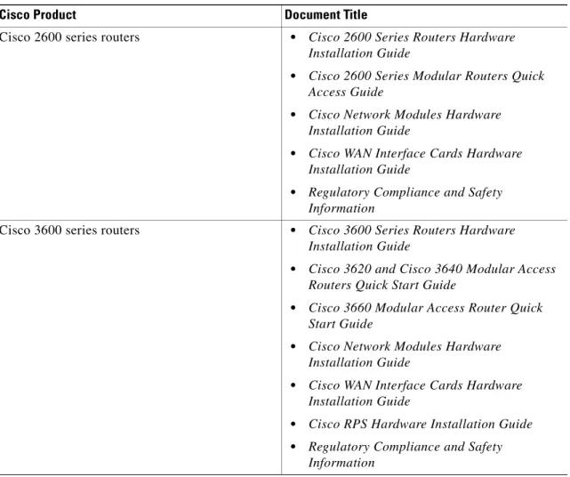
Related and Referenced Documents
The documents described here are available online and on the documentation CD-ROM that you received with your router. To be sure of obtaining the latest information, you should access the online
documentation.
To print a document in its original page format, access the online document, and click on the PDF icon. You can also order printed copies of documents. See the Ordering Documentation.
To Access Online User Documentation (PDF and HTML Formats):
From Cisco.com at http://www.cisco.com, under Service & Support, select Technical Documents and select Cisco Product Documentation.
Access User Documentation on the Documentation CD-ROM (HTML format only):
On the Documentation CD-ROM, select Cisco Product Documentation.
Paths to specific documents are provided below, starting at Cisco Product Documentation.
Tip To navigate up to the next higher level in the documentation hierarchy, click on CONTENTS in the navigation bar at the top of each page.
Table 1 Related and Referenced Documents
Cisco Product Document Title
Cisco 2600 series routers • Cisco 2600 Series Routers Hardware
Installation Guide
• Cisco 2600 Series Modular Routers Quick
Access Guide
• Cisco Network Modules Hardware
Installation Guide
• Cisco WAN Interface Cards Hardware
Installation Guide
• Regulatory Compliance and Safety
Information
Cisco 3600 series routers • Cisco 3600 Series Routers Hardware
Installation Guide
• Cisco 3620 and Cisco 3640 Modular Access
Routers Quick Start Guide
• Cisco 3660 Modular Access Router Quick
Start Guide
• Cisco Network Modules Hardware
Installation Guide
• Cisco WAN Interface Cards Hardware
Installation Guide
• Cisco RPS Hardware Installation Guide
• Regulatory Compliance and Safety
Cisco 3700 series routers • Cisco 3700 Series Routers Hardware Installation Guide
• Cisco 3725 and Cisco 3745 Modular Access
Routers Quick Start Guide
• Cisco Network Modules Hardware
Installation Guide
• Cisco WAN Interface Cards Hardware
Installation Guide
• Regulatory Compliance and Safety
Information
Cisco IOS software
Note Refer to the modular reference publication that corresponds to the Cisco IOS software release installed on your server.
• Cisco IOS Configuration Fundamentals
Configuration Guide
• Cisco IOS Configuration Fundamentals
Command Reference
• Cisco IOS Dial Technologies Configuration
Guide
• Cisco IOS Wide-Area Networking
Configuration Guide
• Cisco IOS IP Configuration Guide
Release 12.2
• Cisco IOS Wide-Area Networking Command
Reference
• Debug Command Reference
• System Error Messages
• Cisco IOS Software Command Summary
• Cisco IOS Release notes for your release
Table 1 Related and Referenced Documents (continued)
Obtaining Documentation
The following sections provide sources for obtaining documentation from Cisco Systems.
World Wide Web
You can access the most current Cisco documentation on the World Wide Web at the following sites: • http://www.cisco.com
• http://www-china.cisco.com • http://www-europe.cisco.com
Other documents • Information about TL1 commands can be
found in the Telcordia Technology (formerly Bellcore) document Network Maintenance:
Network Element and Transport Surveillance Messages, GR-833-CORE, Issue 5,
November 1996. For a reference of
security-related commands (ACT-USER and CANC-USER) refer to Telcordia
Technology’s Operations Applications
Messages-Network Element and Network System Security Admin Messages,
TR-NWT-000835, Issue 2, January 1993. • Information about the PRI network module,
refer to the 1-Port and 2-Port ISDN-PRI
Network Module Configuration Note. For
information on how to install an Ethernet module, refer to the 1-Port Ethernet Network
Module Configuration Note or the 4-Port Ethernet Network Module Configuration Note.
• For information on how to correctly install and configure the Digital Network module and the PRI module, refer to the Digital
Modem Network Module Configuration Note.
• To configure the router for voice traffic, refer to the Voice over IP Configuration document • To configure DLAMs, refer to the
Configuration Guide for DSLAs with NI-2.
Table 1 Related and Referenced Documents (continued)
Documentation CD-ROM
Cisco documentation and additional literature are available in a CD-ROM package, which ships with your product. The Documentation CD-ROM is updated monthlyand may be more current than printed documentation. The CD-ROM package is available as a single unit or as an annual subscription.
Ordering Documentation
Cisco documentation is available in the following ways:
• Registered Cisco Direct Customers can order Cisco Product documentation from the Networking Products MarketPlace:
http://www.cisco.com/cgi-bin/order/order_root.pl
• Registered Cisco.com users can order the Documentation CD-ROM through the online Subscription Store:
http://www.cisco.com/go/subscription
• Nonregistered Cisco.com users can order documentation through a local account representative by calling Cisco corporate headquarters (California, USA) at 408 526-7208 or, in North America, by calling 800 553-NETS(6387).
Documentation Feedback
If you are reading Cisco product documentation on the World Wide Web, you can submit technical comments electronically. Click Feedback in the toolbar and select Documentation. After you complete the form, click Submit to send it to Cisco.
You can e-mail your comments to [email protected].
To submit your comments by mail, for your convenience many documents contain a response card behind the front cover. Otherwise, you can mail your comments to the following address:
Cisco Systems, Inc.
Document Resource Connection 170 West Tasman Drive
San Jose, CA 95134-9883 We appreciate your comments.
Obtaining Technical Assistance
Cisco provides Cisco.com as a starting point for all technical assistance. Customers and partners can obtain documentation, troubleshooting tips, and sample configurations from online tools. For Cisco.com registered users, additional troubleshooting tools are available from the TAC website.
Cisco.com
Cisco.com is the foundation of a suite of interactive, networked services that provides immediate, open access to Cisco information and resources at anytime, from anywhere in the world. This highly integrated Internet application is a powerful, easy-to-use tool for doing business with Cisco.
Cisco.com provides a broad range of features and services to help customers and partners streamline business processes and improve productivity. Through Cisco.com, you can find information about Cisco and our networking solutions, services, and programs. In addition, you can resolve technical issues with online technical support, download and test software packages, and order Cisco learning materials and merchandise. Valuable online skill assessment, training, and certification programs are also available. Customers and partners can self-register on Cisco.com to obtain additional personalized information and services. Registered users can order products, check on the status of an order, access technical support, and view benefits specific to their relationships with Cisco.
To access Cisco.com, go to the following website: http://www.cisco.com
Technical Assistance Center
The Cisco TAC website is available to all customers who need technical assistance with a Cisco product or technology that is under warranty or covered by a maintenance contract.
Contacting TAC by Using the Cisco TAC Website
If you have a priority level 3 (P3) or priority level 4 (P4) problem, contact TAC by going to the TAC website:
http://www.cisco.com/tac
P3 and P4 level problems are defined as follows:
• P3—Your network performance is degraded. Network functionality is noticeably impaired, but most business operations continue.
• P4—You need information or assistance on Cisco product capabilities, product installation, or basic product configuration.
In each of the above cases, use the Cisco TAC website to quickly find answers to your questions. To register for Cisco.com, go to the following website:
http://www.cisco.com/register/
If you cannot resolve your technical issue by using the TAC online resources, Cisco.com registered users can open a case online by using the TAC Case Open tool at the following website:
http://www.cisco.com/tac/caseopen
Contacting TAC by Telephone
If you have a priority level 1(P1) or priority level 2 (P2) problem, contact TAC by telephone and immediately open a case. To obtain a directory of toll-free numbers for your country, go to the following website:
P1 and P2 level problems are defined as follows:
• P1—Your production network is down, causing a critical impact to business operations if service is not restored quickly. No workaround is available.
• P2—Your production network is severely degraded, affecting significant aspects of your business operations. No workaround is available.
C H A P T E R
1
Understanding Interface Numbering and
Cisco IOS Software Basics
This chapter provides an overview of the interface numbering in the Cisco 2600 series, Cisco 3600 series, and Cisco 3700 series routers. It also describes how to use the Cisco IOS software commands.
Understanding Interface Numbering
This section contains information with which you should be familiar before you begin to configure your router for the first time, including interface numbering and what you should do before starting your router.
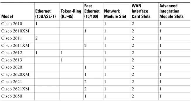
Cisco 2600 Series Interface Numbering
Each network interface on a Cisco 2600 series router is identified by a slot number and a unit number. Table 1-1 lists the router models and summarizes the interfaces supported on each model that are available in the Cisco 2600 series routers.
Table 1-1 Summary of Cisco 2600 Series Router Models and Interfaces
Model Ethernet (10BASE-T) Token-Ring (RJ-45) Fast Ethernet (10/100) Network Module Slot WAN Interface Card Slots Advanced Integration Module Slots Cisco 2610 1 1 2 1 Cisco 2610XM 1 1 2 1 Cisco 2611 2 1 2 1 Cisco 2611XM 2 1 2 1 Cisco 2612 1 1 1 2 1 Cisco 2613 1 1 2 1 Cisco 2620 1 1 2 1 Cisco 2620XM 1 1 2 1 Cisco 2621 2 1 2 1 Cisco 2621XM 2 1 2 1 Cisco 2650 1 1 2 1
Note The number and type of interfaces vary depending on the router.
WAN and LAN Interface Numbering
The Cisco 2600 series router chassis contains the following wide-area network (WAN) and local-area network (LAN) interface types:
• Built-in LAN interfaces: Ethernet, FastEthernet, Token Ring
• Two or three slots in which you can install WAN interface cards (WICs) • One slot in which you can install a network module
The numbering format is Interface-type Slot-number/Interface-number. Two examples are:
Ethernet 0/0 Serial 1/2
The slot number is 0 for all built-in interfaces and 0 for all WIC interfaces; the slot number is 1 for network module interfaces.
Interface (port) numbers begin at 0 for each interface type, and continue from right to left and (if necessary) from bottom to top.
Figure 1-1 below shows a router of 1 RU height with:
• A WIC in each WIC slot (containing interface Serial 0/0 in physical slot W0, and interface Serial 0/1 in physical slot W1)
• A 4-serial-port network module in slot 1 (containing the following ports: Serial 1/0, Serial 1/1, Serial 1/2, and Serial 1/3)
• First built-in Ethernet interface—Ethernet 0/0
• Second built-in Ethernet interface—Ethernet 0/1, or optionally in Cisco 2612 and Cisco 2613 only: Token Ring interface 0/0
Cisco 2650XM 1 1 2 1
Cisco 2651 2 1 2 1
Cisco 2651XM 2 1 2 1
Cisco 2691 2 1 3 2
Table 1-1 Summary of Cisco 2600 Series Router Models and Interfaces (continued)
Model Ethernet (10BASE-T) Token-Ring (RJ-45) Fast Ethernet (10/100) Network Module Slot WAN Interface Card Slots Advanced Integration Module Slots
Figure 1-1 Example of 1RU Router
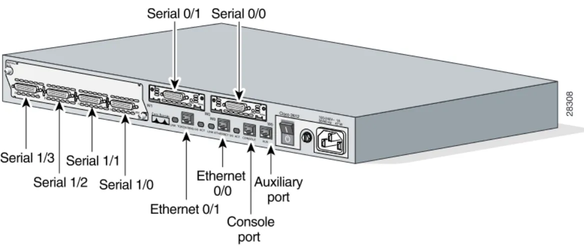
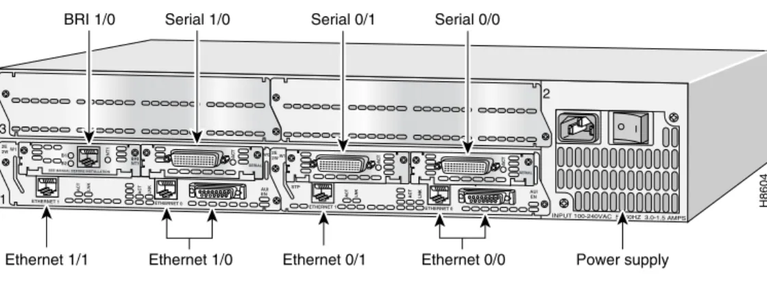
Figure 1-2 below shows a router of 2 RU height with:
• A WIC in each WIC slot (containing interfaces Serial 0/0 and Serial 0/1 in physical slot W0, interface Serial 0/2 in physical slot W1, and interface BRI 0/0 in physical slot W2)
• A 2-port T1 network module in slot 1 (containing the following ports: T1 1/0 and T1 1/1) • Two built-in Ethernet 10/100 interfaces—FastEthernet 0/0 and FastEthernet 0/1
Figure 1-2 Example of a 2RU Router
28308 Cisco 2612 100-240V– 1A50/60 Hz 47 W Serial 1/0 Serial 1/2 Serial 1/1 Serial 1/3 W1 CN/LP 2 1 0 3RXC RXDTXCTXD CN/LP RXC RXDTXCTXD CN/LP RXC RXDTXCTXD CN/LP RXC RXDTXCTXD EN SERIAL A/S W0 SERIAL CONN W0 SERIAL CONN AUX CONSOLE ETHERNET 0/0 ACT LINK ACT TOKEN RING 0/0 LINK W0 Ethernet 0/0 Auxiliaryport Console port Ethernet 0/1 Serial 0/0 Serial 0/1 BANK 4BA NM-HDV
Note The slot number for all WIC interfaces is always 0. (The W0 and W1 slot designations are for physical slot identification only.) Interfaces in the WICs are numbered from right to left, starting with 0/0 for each interface type, regardless of which physical slot the WICs are installed in. Some examples are:
– If physical slot W0 is empty and physical slot W1 contains a 1-port serial WIC, the interface number in the WIC is numbered Serial 0/0.
– If slot W0 contains a 2-port serial WIC and slot W1 contains a 1-port serial WIC, the interfaces in physical slot W0 are numbered Serial 0/0 and Serial 0/1, and the interface in physical slot W1 is numbered Serial 0/2.
– If slot W0 contains a 2-port serial WIC and slot W1 contains a 1-port BRI WIC, the interfaces in physical slot W0 are numbered Serial 0/0 and Serial 0/1, and the interface in physical slot W1 is numbered BRI 0/0.
Voice Interface Numbering in Cisco 2600 Series Routers
Voice interfaces are numbered differently from the WAN interfaces described in the previous section. Voice interfaces are numbered as follows:
chassis slot/voice module slot/voice interface
If a 4-channel voice network module is installed in chassis slot 1, the voice interfaces are: • 1/0/0—Chassis slot 1/Voice module slot 0/Voice interface 0
• 1/0/1—Chassis slot 1/Voice module slot 0/Voice interface 1 • 1/1/0—Chassis slot 1/Voice module slot 1/Voice interface 0 • 1/1/1—Chassis slot 1/Voice module slot 1/Voice interface 1
Cisco 3600 Series Interface Numbering
Each individual network interface on a Cisco 3600 series router is identified by a slot number and a unit number.
Cisco 3600 Series Router Slot Numbering
A Cisco 3600 series router chassis includes up to six slots in which you can install modules. The Cisco 3600 series includes the Cisco 3660 (see Figure 1-3), Cisco 3640 (see Figure 1-4) and Cisco 3620 routers (see Figure 1-5). The Cisco 3660 has six network module slots, the Cisco 3640 has four slots, the Cisco 3620 has two slots, and the Cisco 3631 (see Figure 1-6) has four slots. You can install any module into any available slot in the chassis.
Figure 1-3 Cisco 3660 Router Rear View
Figure 1-4 Cisco 3640 Router Rear View
Figure 1-5 Cisco 3620 Router Rear View
18030 VCC OK SYSTEM FDX LINK 100Mbps FDX 1 0 LINK 100Mbps ETH 0 ETH 3 ETHERNET 4E ETH 2 ETH 1 1 2 3 ACT LINK 0 CN/LP RXC
SERIAL 3 SERIAL 2 SERIAL 1 SERIAL 0
RXDTXCTXD CN/LP RXC RXD TXC TXD CN/LP RXC RXD TXC TXD CN/LP RXC RXD TXC TXD EN SERIAL 4T VOICE 2V V0 V1 EN
HIGH SPEED SERIAL 1HSSI H TD TC RD RC LB/CN Slot 5 Slot 3 Slot 1 Slot 6 Slot 4 Slot 2
SEE MANUAL BEFORE INSTALLATION VIC FXS IN USE IN USE 1 0 Slot 0 Slot 0
Slot 1 Power supply
Slot 3
H6551
INPUT 100-240VAC 50/60HZ 3.0-1.5 AMPS 2E 2WW1 ETHERNET 1 ETHERNET 0 EN AUI WO ACT LNK ACT LNK AC T SERIAL BRI NT1 B1 B2 NT1 2 3 1 2E 2WW1 STP ETHERNET 0 AUI EN ACT LNK ACT LNK
DO NOT INSTALL WAN INTERFACE CARDS WITH POWER APPLIED
Slot 2
AC
T
SERIAL SEE MANUAL BEFORE INSTALLATION
ETHERNET 1 2E 2WW1 1 ETHERNET 1 ETH 1 ETHERNET 0 EN AUI WO ACT LNK ACT LNK AC T SERIAL BRI NT1 B1 B2 NT1 2E 2WW1 ETHERNET 0 AUI EN ACTLNK ACT LNK DO NOT INSTALL WAN INTERFACECARDS WITH POWER APPLIED
AC
T
SERIAL
SEE MANUAL BEFORE INSTALLATION
Slot 0
H7238
Slot 1
0
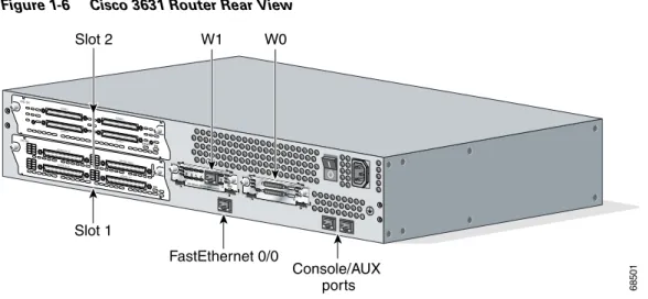
Figure 1-6 Cisco 3631 Router Rear View
For the Cisco 3660 router (see Figure 1-3), the slots are numbered as follows: • Slot 0 contains fixed FastEthernet ports and is located at the top of the chassis.
• Slot 1 is at the bottom right (as viewed from the rear of the chassis), near the power supply. • Slot 2 is at the bottom left.
• Slot 3 is at the right, above slot 1. • Slot 4 is at the left, above slot 2 • Slot 5 is at the right, above slot 3. • Slot 6 is at the left, above slot 4.
For the Cisco 3620 and Cisco 3640 routers shown in Figure 1-4 and Figure 1-5, the slots are numbered as follows:
• Slot 0 is at the bottom right (as viewed from the rear of the chassis), near the power supply. • Slot 1 is at the bottom left.
• Slot 2 is at the top right, above slot 0. • Slot 3 is at the top left, above slot 1.
For the Cisco 3631 router shown in Figure 1-6, the slots are numbered as follows:
• Slot 0 for all built-in interfaces like the FastEthernet port at the bottom center near the Console/AUX ports
• Slot 0 for all WAN interface card (WIC) interfaces • Slot 1 for network module interfaces at the bottom left.
• Slot 2 for network module interfaces at the top left, above slot 1.
68501
SEE MANUAL BEFORE INS TALLATION AL CD LP RD TD
SEE MANUAL BEFORE INS TALLATION DSU 56K EN AIC-64 CONN 2 STAT CONN 4 CONN 1 CONN 3 EN ASYNC ASYNC 8-15 ASYNC 0-7 15 14 13 12 11 10 9 8 7 6 5 4 3 2 1 0 ASYNC 24-31 ASYNC 16-23 31 30 29 28 27 26 25 24 23 22 21 20 19 18 17 16 W1 Slot 2 W0 Console/AUX ports FastEthernet 0/0 Slot 1
Figure 1-7 Example of the Cisco 3631 Router Interface Numbering
Figure 1-7 shows an example of the interface numbering where the following interfaces are installed: • A WIC in each WIC slot (containing interfaces serial 0/0 and serial 0/1 in physical slot W0, and
interface serial 0/2 in physical slot W1)
• A 32-port asynchronous network module in slot 1 (containing interfaces serial 1/0 through serial 1/31)
• An alarm interface controller network module in slot 2 (internally connected to interface serial 2/0) • One built-in Ethernet 10/100 interface—FastEthernet 0/0
Note The logical slot number for all WIC interfaces is always 0. (The W0 and W1 slot designations are for physical slot identification only.) Interfaces in the WICs are numbered from right to left, starting with 0/0 for each interface type, regardless of which physical slot the WICs are installed in. Some examples are:
– If physical slot W0 is empty and physical slot W1 contains a 1-port serial WIC, then the logical interface in the WIC is numbered serial 0/0.
– If physical slot W0 contains a 2-port serial WIC and slot W1 contains a 1-port serial WIC, then the logical interfaces in physical slot W0 are numbered serial 0/0 and serial 0/1 and the logical interface in physical slot W1 is numbered Serial 0/2.
– If physical slot W0 contains a 2-port serial WIC and slot W1 contains a 1-port BRI WIC, then the logical interfaces in physical slot W0 are numbered serial 0/0 and serial 0/1, and the logical interface in physical slot W1 is numbered BRI 0/0.
62052
SEE MANUAL BEFORE INSTALLATION
AL
CD
LP
RD
TD
SEE MANUAL BEFORE INSTALLATION DSU 56K EN AIC-64 CONN 2 STAT CONN 4 CONN 1 CONN 3 EN ASYNC ASYNC 8-15 ASYNC 0-7 15 14 13 12 11 10 9 8 7 6 5 4 3 2 1 0 ASYNC 24-31 ASYNC 16-23 31 30 29 28 27 26 25 24 23 22 21 20 19 18 17 16 Serial 0/2 Serial 1/0 to 1/7 Serial 1/16 to 1/23 Serial 1/8 to 1/15 Serial 1/24 to 1/31
Internal connections to serial 2/0
Console/AUX ports FastEthernet 0/0
Serial 0/0 Serial 0/1
Some modules have two small slots, labeled W0 and W1, for WAN interface cards. For example, Figure 1-8 shows the W0 and W1 slots of the 2 Ethernet 2 WAN card slot (2E 2-slot) module. You can install WAN interface cards into the small module slots (W0 and W1). Integrated Services Digital Network (ISDN) Basic Rate Interface (BRI) WAN interface cards are keyed so that you can install them into slot W1 only. Serial WAN interface cards can be installed into either slot, W0 or W1.
Figure 1-8 WAN Interface Card Slots
Cisco 3600 Series Router Unit Numbering
Cisco 3600 series routers unit numbers identify the interfaces on the modules and WAN interface cards installed in the router. Unit numbers begin at 0 for each interface type, and continue from right to left and (if necessary) from bottom to top. Modules and WAN interface cards are identified by interface type, slot number, followed by a forward slash
(/), and then the unit number; for example, Ethernet 0/0.
Note In the Cisco 3660 router, the fixed FastEthernet ports are located in chassis slot 0, and are identified by:
interface type chassis slot/ unit number
For example: FastEthernet 0/0
Figure 1-9 shows a router with a 2E 2-slot module in slots 0 and 1. Two serial WAN interface cards are installed in the module in slot 0. One serial and one ISDN BRI WAN interface card are installed in the module in slot 1.
As shown in Figure 1-9, the unit numbers are as follows: • Slot 0, Ethernet interface 0, referred to as Ethernet 0/0 • Slot 0, Ethernet interface 1, referred to as Ethernet 0/1 • Slot 0, serial interface 0, referred to as serial 0/0 • Slot 0, serial interface 1, referred to as serial 0/1 • Slot 1, Ethernet interface 0, referred to as Ethernet 1/0 • Slot 1, Ethernet interface 1, referred to as Ethernet 1/1 • Slot 1, serial interface 0, referred to as serial 1/0 • Slot 1, BRI interface 0, referred to as BRI 1/0
Note The 2E 2-slot module described in this example provides both an attachment unit interface (AUI) and 10BASE-T port. Only one of these ports can be used at a time. The module automatically detects which port, AUI or 10BASE-T, is in use.
2E 2WW1 STP ETHERNET 0 ETHERNET 1 AUI EN ACT LNK WO ACT ILNK Slot W1 Slot W0 H8603
Cisco 3600 Series Routers Voice Interface Numbering
Voice interfaces are numbered differently from WAN interfaces described in the previous section, “Cisco 3600 Series Router Unit Numbering.” Voice interfaces are numbered as follows:
interface type chassis slot/voice module slot/voice interface
If you have a 4-channel voice network module installed in slot 1 of your router, the voice interfaces will be:
• Slot 1, voice network module slot 0, voice interface 0, referred to as voice 1/0/0 (closest to chassis slot 0)
• Slot 1, voice network module slot 0, voice interface 1, referred to as voice 1/0/1 • Slot 1, voice network module slot 1, voice interface 0, referred to as voice 1/1/0
• Slot 1, voice network module slot 1, voice interface 1, referred to as voice 1/1/1 (farthest from chassis slot 0)
Figure 1-9 Cisco 3600 Series Unit Numbers
Cisco 3700 Series Interface Numbering
Each WAN and LAN interface on a Cisco 3700 series router is identified by a slot number and a unit number. The Cisco 3700 series includes the Cisco 3725 and Cisco 3745.
Cisco 3725 Router Interface Numbering
The Cisco 3725 router chassis contains the following wide-area network (WAN) and local area network (LAN) interface types:
• Two built-in FastEthernet LAN interfaces
• Three slots in which you can install WAN interface cards (WICs)
• One single-width slot (slot 1) in which you can install one network module
• One double-width slot (slot 2) in which you can install one single-width or double-width network module
Power supply BRI 1/0
Ethernet 1/0 Ethernet 0/1 Ethernet 0/0
Ethernet 1/1
H8604
INPUT 100-240VAC 50/60HZ 3.0-1.5 AMPS 2E 2WW1 ETHERNET 1 ETHERNET 0 EN AUI WO ACT LNK ACT LNK AC T SERIAL BRI NT1 B1 B2 NT1 2 3 1 2E 2WW1 STP ETHERNET 0 AUI EN ACT LNK ACT LNK AC T SERIAL AC T
SEE MANUAL BEFORE INSTALLATION
ETHERNET 1
Cisco 3725 Router Slot Numbering
The numbering format is Interface-type Slot-number/Interface-number. Two examples are:
FastEthernet 0/0 Serial 1/2.
The slot numbers are as follows: • 0 for all built-in interfaces • 0 for all WIC interfaces
• 1 for interfaces in the single-width network module slot • 2 for interfaces in the double-width network module slot
Interface (port) numbers begin at 0 for each interface type, and continue from right to left and (if necessary) from bottom to top.
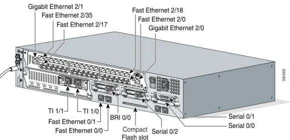
Figure 1-10 below shows an example of interface numbering on a Cisco 3725 router with: • A WIC in each WIC slot (containing interfaces Serial 0/0 and Serial 0/1 in physical slot W0,
interface Serial 0/2 in physical slot W1, and interface BRI 0/0 in physical slot W2) • A 2-port T1 network module in slot 1 (containing the following ports: T1 1/0 and T1 1/1) • A 36-port Etherswitch network module in slot 2 (containing the following ports: FastEthernet 2/0
through 2/35, and GigabitEthernet 2/0 and 2/1)
• Two built-in Ethernet 10/100 interfaces—FastEthernet 0/0 and FastEthernet 0/1
Figure 1-10 Cisco 3725 Router Rear View
Serial 0/2 Compact
Flash slot
56482
SEE MANUAL BEFORE INS TALLATION AL CD LP RD TD
SEE MANUAL BEFORE INSTALLATION DSU 56K AL CD LP RD TD
SEE MANUAL BEFORE INS TALLATION DSU 56K EN V0 BANK 4BANK 3 BANK 2 BANK 1 BANK 0 NM-HDV VWIC 2MFT-E1 SEE MANUAL BEFORE INSTALLATION CTRLR E2 CTRLR E1 AL LP CD Gigabit Ethernet 2/1 Fast Ethernet 2/35 Fast Ethernet 2/17 Gigabit Ethernet 2/0 Fast Ethernet 2/0 Fast Ethernet 2/18 Serial 0/1 Serial 0/0 TI 1/1 TI 1/0 Fast Ethernet 0/1 Fast Ethernet 0/0 BRI 0/0 1 2
Note The slot number for all WIC interfaces is always 0. (The W0 and W1 slot designations are for physical slot identification only.) Interfaces in the WICs are numbered from right to left, starting with 0/0 for each interface type, regardless of which physical slot the WICs are installed in. Some examples are:
– If physical slot W0 is empty and physical slot W1 contains a 1-port serial WIC, the interface in the WIC is numbered Serial 0/0.
– If slot W0 contains a 2-port serial WIC and slot W1 contains a 1-port serial WIC, the interfaces in physical slot W0 are numbered Serial 0/0 and Serial 0/1, and the interface in physical slot W1 is numbered Serial 0/2.
– If slot W0 contains a 2-port serial WIC and slot W1 contains a 1-port BRI WIC, the interfaces in physical slot W0 are numbered Serial 0/0 and Serial 0/1, and the interface in physical slot W1 is numbered BRI 0/0.
Cisco 3745 Router Interface Numbering
The Cisco 3745 router chassis contains the following wide-area network (WAN) and local-area network (LAN) interface types:
• 2 built-in FastEthernet LAN interfaces
• 3 slots in which you can install WAN or voice interface cards • 4 network module slots.
Cisco 3745 Router Slot Numbering
The numbering format in the Cisco 3745 router is Interface type Slot number/Interface number. Two examples are:
FastEthernet 0/0 Serial 1/2.
The slot numbers are as follows: • 0 for all built-in interfaces • 0 for all WIC interfaces
• 1 for the lower right network module slot • 2 for the lower left network module slot • 3 for the upper right network module slot • 4 for the upper left network module slot
If double-wide network modules are installed, the slot numbers are as follows: • 2 for the lower double-wide slot
• 4 for the upper double-wide slot
Interface (port) numbers begin at 0 for each interface type, and continue from right to left and (if necessary) from bottom to top.
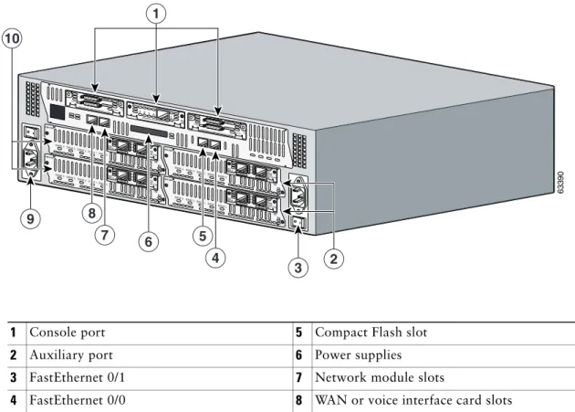
Figure 1-11 shows the rear panel of the Cisco 3745 with: • A WIC in each of the three WAN interface card slots
• A single-width network module in each of the four network module slots • Two AC power supplies
Figure 1-11 Cisco 3745 Rear Panel
Note The slot number for all WIC interfaces is always 0. (The W0, W1, and W2 slot designations are for physical slot identification only.) Interfaces in the WICs are numbered from right to left, starting with 0/0 for each interface type, regardless of which physical slot the WICs are installed in. Some examples are:
– If physical slot W0 is empty and physical slot W1 contains a 1-port serial WIC, the interface in the WIC is numbered Serial 0/0.
– If slot W0 contains a 2-port serial WIC and slot W1 contains a 1-port serial WIC, the interfaces in physical slot W0 are numbered Serial 0/0 and Serial 0/1, and the interface in physical slot W1 is numbered Serial 0/2.
– If slot W0 contains a 2-port serial WIC and slot W1 contains a 1-port BRI WIC, the interfaces in physical slot W0 are numbered Serial 0/0 and Serial 0/1, and the interface in physical slot W1 is numbered BRI 0/0.
1 Console port 5 Compact Flash slot
2 Auxiliary port 6 Power supplies
3 FastEthernet 0/1 7 Network module slots
4 FastEthernet 0/0 8 WAN or voice interface card slots
63390
EN V0
BANK 4BANK 3BANK 2 BANK 1 BANK 0 NM-HDV VWIC 2MFT-E1 SEE MANUAL BEFORE INSTALLATION CTRLR E2 CTRLR E1 AL LP CD EN V0 BANK 4 BANK 3BANK 2BANK 1 B
ANK 0 NM-HDV VWIC 2MFT-E1 SEE MANUAL BEFORE INSTALLATION CTRLR E2 CTRLR E1 AL LP CD EN V0 BANK 4 BANK 3BANK 2BANK 1 B
ANK 0 NM-HDV VWIC 2MFT-E1 SEE MANUAL BEFORE INSTALLA TION CTRLR E2 CTRLR E1 AL LP CD EN V0 BANK 4BANK 3 BANK 2BANK 1 BANK 0
NM-HDV
VWIC 2MFT-E1 SEEMANUAL
BEFORE INSTALLATION CTRLR E2 CTRLR E1 AL LP CD SEE MANUAL BEFO
RE INSTALLATION SERIAL 1 SERIAL 0 CONN CONNWIC 2T
SEE MANUAL BEFO RE INSTALLATION SERIAL 1 SERIAL 0 CONN CONNWIC 2T SEE MANUAL BEFO
RE INSTALLATION DSU 56K CD A L LP RD TD 8 7 6 9 3 5 4 2 1 10
Cisco 3700 Series Routers Voice Interface Numbering
Voice interfaces in Cisco 3725 and Cisco 3745 routers are numbered differently from the WAN interfaces described in the previous section Voice interfaces are numbered as follows:
chassis slot/voice module slot/voice interface
If a 4-channel voice network module is installed in chassis slot 1, the voice interfaces are: • 1/0/0—Chassis slot 1/Voice module slot 0/Voice interface 0
• 1/0/1—Chassis slot 1/Voice module slot 0/Voice interface 1 • 1/1/0—Chassis slot 1/Voice module slot 1/Voice interface 0 • 1/1/1—Chassis slot 1/Voice module slot 1/Voice interface 1
Understanding Cisco IOS Software Basics
This section describes what you need to know about the Cisco IOS software before you configure the router using the command-line interface (CLI). This chapter includes the following:
• Getting Help, page 1-13
• Understanding Command Modes, page 1-14 • Undoing a Command or Feature, page 1-15 • Saving Configuration Changes, page 1-15 • Where to Go Next, page 1-15
Understanding these concepts will save time as you begin to use the CLI. If you have never used the Cisco IOS software or need a refresher, take a few minutes to read this chapter before you proceed to the next chapter.
If you are already familiar with Cisco IOS software, proceed to Chapter 2, “Using the Setup Command Facility.”
Getting Help
Use the question mark (?) and arrow keys to help you enter commands: • For a list of available commands, enter a question mark:
Router> ?
• To complete a command, enter a few known characters followed by a question mark (with no space):
Router> s?
• For a list of command variables, enter the command followed by a space and a question mark:
Router> show ?
• To redisplay a command you previously entered, press the up arrow key. You can continue to press the up arrow key for more commands.
Understanding Command Modes
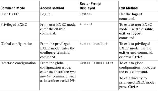
The Cisco IOS user interface is divided into different modes. Each command mode permits you to configure different components on your router. The commands available at any given time depend on which mode you are currently in. Entering a question mark (?) at the prompt displays a list of commands available for each command mode. Table 1-2 lists the most common command modes.
Timesaver Each command mode restricts you to a subset of commands. If you are having trouble entering a command, check the prompt, and enter the question mark (?) for a list of available commands. You might be in the wrong command mode or using the wrong syntax.
In the following example, notice how the prompt changes after each command to indicate a new command mode:
Router> enable
Password: <enable password> Router# configure terminal
Router(config)# interface serial 0/0 Router(config-if)# line 0
Router(config-line)# controller t1 0 Router(config-controller)# exit Router(config)# exit
Router#
%SYS-5-CONFIG_I: Configured from console by console
The last message is normal and does not indicate an error. Press Return to get the Router# prompt.
Table 1-2 Common Command Modes
Command Mode Access Method
Router Prompt
Displayed Exit Method
User EXEC Log in. Router> Use the logout
command. Privileged EXEC From user EXEC mode,
enter the enable command.
Router# To exit to user EXEC
mode, use the disable, exit, or logout
command. Global configuration From the privileged
EXEC mode, enter the configure terminal command.
Router (config)# To exit to privileged
EXEC mode, use the exit or end command, or press Ctrl-z. Interface configuration From the global
configuration mode, enter the interface type
number command, such
as interface serial 0/0.
Router (config-if)# To exit to global
configuration mode, use the exit command. To exit directly to privileged EXEC mode, press Ctrl-z.
Note You can press Ctrl-z in any mode to immediately return to enable mode (Router#), instead of
entering exit, which returns you to the previous mode.
Undoing a Command or Feature
If you want to undo a command you entered or disable a feature, enter the keyword no before most commands; for example, no ip routing.
Saving Configuration Changes
You need to enter the copy running-config startup-config command to save your configuration changes to nonvolatile random-access memory (NVRAM), so the changes are not lost if there is a system reload or power outage. For example:
Router# copy running-config startup-config Building configuration...
It might take a minute or two to save the configuration to NVRAM. After the configuration has been saved, the following appears:
[OK] Router#
Upgrading to a New Cisco IOS Release
To install or upgrade to a new Cisco IOS release, refer to Appendix B, “Formatting the Compact Flash Memory Cards.”
Where to Go Next
Now that you have learned some Cisco IOS software basics, you can begin to configure the router using the CLI.
Remember that:
• You can use the question mark (?) and arrow keys to help you enter commands.
• Each command mode restricts you to a set of commands. If you have difficulty entering a command, check the prompt and then enter the question mark (?) for a list of available commands. You might be in the wrong command mode or using the wrong syntax.
• To disable a feature, enter the keyword no before the command; for example, no ip routing. • You need to save your configuration changes to NVRAM so the changes are not lost if there is a
system reload or power outage.
C H A P T E R
2
Using the Setup Command Facility
This chapter describes how to use the setup command facility to configure your router. The setup command facility prompts you to enter information needed to start a router functioning quickly. The facility steps you through a basic configuration, including local-area network (LAN) and wide-area network (WAN) interfaces. The following sections are included:
• Before Starting Your Router, page 2-1 • Using the setup Command Facility, page 2-2 • Configuring Global Parameters, page 2-2 • Configuring Interface Parameters, page 2-6 • Completing the Configuration, page 2-24 • Where to Go Next, page 2-25
If you prefer to configure the router manually or you wish to configure a module or interface that is not included in the setup command facility, proceed to “Chapter 3, “Configuring with the Command-Line Interface,” for step-by-step instructions.
Before Starting Your Router
Before you power on your router and begin to use the setup command facility, make sure you follow these steps:
Step 1 Set up the hardware as described in the documentation appropriate to your router.
Step 2 Configure your PC terminal emulation program for 9600 baud, 8 data bits, no parity, and 1 stop bit. Step 3 Determine which network protocols you are supporting (for example, AppleTalk, IP, Novell IPX, and so
on).
Step 4 Determine the following for each network protocol: • Addressing plan
• Which WAN protocols you will run on each interface (for example, Frame Relay, HDLC, X.25, and so on)
Using the setup Command Facility
The setup command facility displays from your PC terminal emulation program window. To create a basic configuration for your router, do the following:
• Complete the steps in the “Configuring Global Parameters” section on page 2-2.
• Complete the steps in the “Configuring Interface Parameters” section on page 2-6 that apply to your router and network.
• Complete the steps in the “Completing the Configuration” section on page 2-24.
Note If you make a mistake while using the setup command facility, you can exit and run the facility again. Press Ctrl-c, and type setup at the enable mode prompt (2600#).
Configuring Global Parameters
Step 1 Power on the router. The power switch is on the rear panel of the router, at the lower right corner, near the power cord.
Messages will begin to appear in your terminal emulation program window.
Caution Do not press any keys on the keyboard until the messages stop. Any keys pressed during this time are interpreted as the first command typed when the messages stop, which might cause the router to power off and start over. It takes a few minutes for the messages to stop.
The messages look similar to the following:
Note The messages vary, depending on the Cisco IOS software release, interface modules in place in your router, and feature set you select. The screen displays in this section are for reference only and might not exactly reflect the messages on your console.
System Bootstrap, Version 11.3(1)XA, PLATFORM SPECIFIC RELEASE SOFTWARE (fc1) Copyright (c) 1998 by cisco Systems, Inc.
C2600 platform with 32768 Kbytes of main memory rommon 1 b f
program load complete, entry point: 0x80008000, size: 0xef4e0
Self decompressing the image : ############################################### [OK]
Notice: NVRAM invalid, possibly due to write erase.
program load complete, entry point: 0x80008000, size: 0x415b20 Self decompressing the image :
########################################################################################## ########################################################################################## ########################################################################################## ###############[OK]
Use, duplication, or disclosure by the Government is subject to restrictions as set forth in subparagraph (c) of the Commercial Computer Software - Restricted Rights clause at FAR sec. 52.227-19 and subparagraph (c) (1) (ii) of the Rights in Technical Data and Computer Software clause at DFARS sec. 252.227-7013.
Cisco Systems, Inc. 170 West Tasman Drive
San Jose, California 95134-1706
Cisco Internetwork Operating System Software
IOS (tm) C2600 Software (C2600-JS-M), Version 11.3(2)XA, PLATFORM SPECIFIC RELEASE SOFTWARE (fc1)
Copyright (c) 1986-1998 by cisco Systems, Inc. Compiled Tue 10-Mar-98 14:18 by rnapier
Image text-base: 0x80008084, data-base: 0x809CD49C
cisco 2611 (MPC860) processor (revision 0x100) with 24576K/8192K bytes of memory. Processor board ID 04614954
M860 processor, part number 0 mask 32 Bridging software.
X.25 software, Version 3.0.0. 2 Ethernet/IEEE 802.3 interface(s) 3 Serial network interface(s) 32 terminal line(s)
DRAM configuration parity is disabled.
32K bytes of non-volatile configuration memory.
8192K bytes of processor board System flash (Read/Write) System Configuration Dialog
---At any point you may enter a question mark '?' for help. Use ctrl-c to abort configuration dialog at any prompt. Default settings are in square brackets '[]'.
Step 2 When the following message appears, enter yes to begin the initial configuration dialog:
Would you like to enter the initial configuration dialog? [yes/no]:
Note If you answer no to this message, you are prompted to terminate AutoInstall. AutoInstall is a procedure that configures a new router based on the configuration of an existing router. If you terminate AutoInstall, you enter the Cisco IOS software CLI.
Note The interface numbering that appears in the next step is dependent on the type of Cisco modular router platform. This example shows a Cisco 2600 series router.
Step 3 When the following message appears, press Return to see the current interface summary:
First, would you like to see the current interface summary? [yes]:
Any interface listed with OK? value “NO” does not have a valid configuration Interface IP-Address OK? Method Status Protocol
Ethernet0/0 unassigned NO unset up up Serial0/0 unassigned NO unset up down BRI0/0 unassigned NO unset up up Serial0/1 unassigned NO unset up down Serial0/2 unassigned NO unset up down
Step 4 Enter a host name for the router (this example uses 2600):
Configuring global parameters: Enter host name [Router]: 2600
The enable secret is a password used to protect access to privileged EXEC and
configuration modes. This password, after entered, becomes encrypted in the configuration.
Step 5 Enter an enable secret password. This password is encrypted (more secure) and cannot be seen when viewing the configuration:
Enter enable secret: xxxx
The enable password is used when you do not specify an enable secret password, with some older software versions, and some boot images.
Step 6 Enter an enable password that is different from the enable secret password. This password is not encrypted (less secure) and can be seen when viewing the configuration:
Enter enable password: guessme
The virtual terminal password is used to protect access to the router over a network interface.
Step 7 Enter the virtual terminal password, which prevents unauthenticated access to the router through ports other than the console port:
Enter virtual terminal password: guessagain
Step 8 Respond to the following prompts as appropriate for your network:
Configure SNMP Network Management? [yes]: Community string [public]:
Configure LAT? [no]: Configure AppleTalk? [no]: Configure DECnet? [no]: Configure IP? [yes]:
Configure IGRP routing? [yes]:
Your IGRP autonomous system number [1]: 15
Note If you answer no to IGRP, you are prompted to configure RIP.
Configure CLNS? [no]: Configure IPX? [no]: Configure Vines? [no]: Configure XNS? [no]: Configure Apollo? [no]: Configure bridging? [no]: