Fujitsu Semiconductor (Shanghai) Co., Ltd.
Application Note
MCU-AN- 500056-E-10F
2
MC-8FX FAMILY
8-BITMICROCONTROLLER
MB95200 SERIES
ELECTRONIC SAFE DEMO
REFERENCE SOLUTION
APPLICATION NOTE
Electrionic Safe Demo V1.0 Revision History
Revision History
Date Author Change of Records
2009-11-4 Kevin Lin V1.0
This manual contains 18 pages.
1. The products described in this manual and the specifications thereof may be changed without prior notice. To obtain up-to-date information and/or specifications, contact your Fujitsu sales representative or Fujitsu authorized dealer.
2. Fujitsu will not be liable for infringement of copyright, industrial property right, or other rights of a third party caused by the use of information or drawings described in this manual.
3. The contents of this manual may not be transferred or copied without the express permission of Fujitsu. 4. The products contained in this manual are not intended for use with equipment which requires extremely
high reliability such as aerospace equipment, undersea repeaters, nuclear control systems or medical equipments for life support.
5. Some of the products described in this manual may be strategic materials (or special technology) as defined by the Foreign Exchange and Foreign Trade Control Law. In such cases, the products or portions thereof must not be exported without permission as defined under the law.
Electrionic Safe Demo V1.0 CONTENTS
CONTENTS
REVISION HISTORY ... 2
CONTENTS ... 3
1
OVERVIEW ... 4
2
DEMO PLATFORM ... 5
2.1 Platform ... 53
FEATURES ... 6
3.1 Multiple Password Level ... 6
3.2 Alterable Code Length ... 6
3.3 Operation Indication and Error Alarm ... 6
3.4 Low Battery Capacity Alarm ... 6
3.5 Error Lock... 6
3.6 Dual Power Supply Source ... 6
4
FUNCTIONS ... 7
4.1 How to open the Safe... 8
4.2 Main Code Operation ... 8
4.3 User Code Operation ... 8
4.4 Emergency Code ... 9
5
HARDWARE ... 10
5.1 System Block ... 10
5.2 Modules ... 12
6
FIRMWARE ... 15
6.1 Flow Chart of Main Function ... 15
6.2 Firmware Project ... 16
7
MORE INFORMATION ... 17
8
APPENDIX ... 18
8.1 Tables ... 18
Electrionic Safe Demo V1.0 Chapter 1 Overview
1 Overview
Fujitsu Electronic Safe demo set which is based on Fujitsu MB95200 series is a high cost-effective solution.
It consists of the components below:
1 x main board with a MB95F214K
1 x 12-key keyboard
1 x electronic valve
1 x battery case for 4
×
5# batteriesThis demo set supports these features:
Multiple password levels
Alterable code length
Operation and error indications
Low battery capacity alarm
Error lock
Electrionic Safe Demo V1.0 Chapter 2 Demo Platform
2 Demo
Platform
2.1 Platform
The electronic safe system consists of a main board which is combined with a 12-key board, an electronic valve and a battery case for 4 × 5# batteries.
Electrionic Safe Demo V1.0 Chapter 3 Features
3
Features
3.1 Multiple Password Level
The password has three levels of code: main code, user code and emergency code. They are ranked by priority from high to low. Each code is used independently.
3.2 Alterable Code Length
The code length is compatible from 6 to 12 bits.
3.3 Operation Indication and Error Alarm
In this system, a buzzer is used to indicate the operations or errors. When different keys are pressed or error occurs, the buzzer sounds differently to indicate the corresponding status.
(1) 100ms on at 1KHZ means key press. (2) 1s on at 500HZ means correct operation.
(3) 4 times of 100ms on at 250HZ and 50ms off means incorrect operation.
(4) 100ms on at 1KHZ and 50ms off in every 5 minutes means being in 15-minute-lock.
3.4 Low Battery Capacity Alarm
A LED is used to indicate the battery capacity.
(1) Normal
–LED keeps on.
(2) Low –LED flashes at the frequency of 500HZ continually.
3.5 Error Lock
The Safe will lock automatically for 30 seconds when enter an incorrect password 5 times or less, while when an incorrect password is entered for more than 5 times, the Safe will be locked for 15 minutes.
3.6 Dual Power Supply Source
When low battery capacity occurs, the power supply will shift to a backup battery package automatically. User can open the Safe to replace the main batteries first.
Electrionic Safe Demo V1.0 Chapter 4 Functions
4 Functions
The Safe keeps sleeping until being waked up by pressing * or PU1, Figure4-1 shows the
back of the demo. PU1 and PU2 can be found on the back. In wake-up mode, an interval of
longer than 5 seconds between two key-presses will switch the Safe to sleep mode. The main functions of this electronic Safe will be introduced as follow.
PU2
PU1
Electrionic Safe Demo V1.0 Chapter 4 Functions
4.1 How to open the Safe
The Safe have three levels of password. When the Safe is powered on, user can enter a password according to the format below to open it.
a. Press [*].
b. Enter [password]. c. Press [#].
Example: [*] 123456 [#].
4.2 Main Code Operation
Condition: The Safe has been opened by main code.
4.2.1 Set main code
a. Press [*]. b. Enter [5][3]. c. Press [PU2].
d. Enter [main code] [#] twice.
Example: [*] [5][3] [PU2] [543210] [#] [543210] [#].
4.2.2 Modify main code
a. Press [*]. b. Press [0]. c. Press [PU1].
d. Enter [old main code] [#]. e. Enter [new main code] [#] twice.
Example: [*] [0] [PU1] [012345] [#] [543210] [#] [543210] [#].
4.3 User Code Operation
Condition: The Safe has been opened by main code or User code
4.3.1 Set user code
a. Press [PU1].
b. Enter [user code][#] twice.
Example: [PU1] [543210] [#] [543210] [#].
4.3.2 Modify user code
a. Press [*]. b. Press [1]. c. Press [PU1].
d. Enter [old user code] [#].
e. Enter [new user code] [#] twice.
Electrionic Safe Demo V1.0 Chapter 4 Functions
4.4 Emergency Code
Condition: The Safe has been opened by main code or Emergency code.
4.4.1 Set emergency code
a. Press [*]. b. Enter [5][2]. c. Press [PU2].
d. Enter [emergency code][#] twice.
Example: [*] [5][2] [012345] [#] [012345] [#] .
4.4.2 Modify emergency code
a. Press [*]. b. Press [8]. c. Press [PU1].
d. Enter [old emergency code] [#]. e. Enter [new emergency code] [#] twice.
Example: [*] [8] [PU1] [012345] [#] [543210] [#] [543210] [#].
4.4.3 Cancel emergency code
a. Press [*]. b. Press [8]. c. Press [PU2].
d. Enter [1234567890] [#].
Electrionic Safe Demo V1.0 Chapter 5 Hardware
5 Hardware
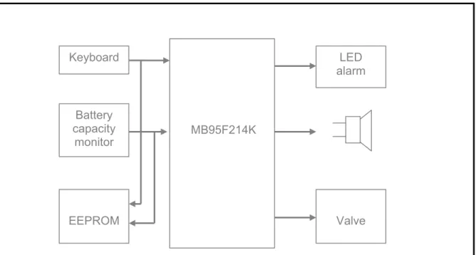
5.1 System Block
The whole system consists of 7 blocks: -MCU
-Key input
-Electronic valve driver lve driver -Power interface -Power interface -EEPROM -EEPROM
-Battery capacity monitoring and alarm -Battery capacity monitoring and alarm -Buzzer
-Buzzer
A system block diagram is shown in Figure5-1. A system block diagram is shown in Figure5-1.
MB95F214K Keyboard Battery capacity monitor LED alarm EEPROM Valve
Figure 5-1: System Block Diagram Figure 5-1: System Block Diagram
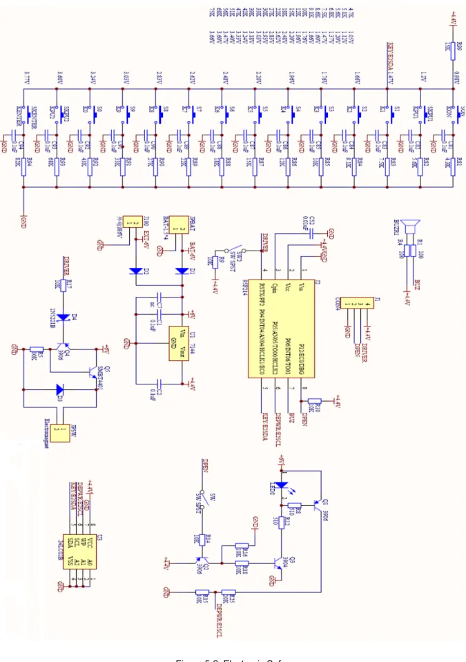
In this demo, many functions share the same pin and completed perfectly. In this demo, many functions share the same pin and completed perfectly. Please refer to Figure 5-2 for details (see next page).
Please refer to Figure 5-2 for details (see next page).
Electrionic Safe Demo V1.0 Chapter 5 Hardware
Electrionic Safe Demo V1.0 Chapter 5 Hardware
5.2 Modules
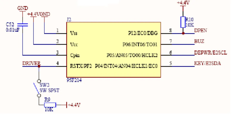
■ MCU
The MCU is MB95F214K, an 8 pins IC with 16K bytes FLASH, 496 bytes RAM and 5 general I/Os.
Figure 5-3: MCU Table 5-1: Pin Function
Number Pin Direction Function 4 RSTX/PF2 OUTPUT Electronic valve drive
5 P04/INT04/AN04/HCLK1/EC0 INPUT Key input, E2 SDA pin
6 P05/AN05/TO00/HCLK2 INPUT Battery capacity monitoring,E2 SCL pin 7 P06/INT06/TO01 OUTPUT Buzzer output
8 P12/EC0/DBG OUTPUT Battery capacity monitoring enable, LED
■
Power interface
The demo has two power supplies. When the LED flashes to indicate low battery capacity, a backup battery package will work. User can open the Safe to replace the 5# batteries. D1 and D2 are used to prevent the counter current.
Electrionic Safe Demo V1.0 Chapter 5 Hardware
■
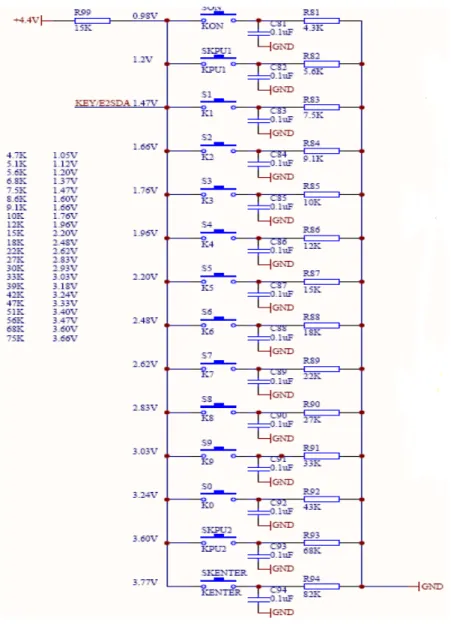
Key input
The key scan is implemented via only one AD channel. When MCU is sleeping, the pin acts as a general I/O to monitor the high-to-low eagle from key input that will produce an interrupt to wake the MCU up. After being waked up, the pin will be set to analog input for scanning keys.
Figure 5-5: Key Input
■
EEPROM
The EEPROM shares pins with the key input and battery capacity monitoring. When the EEPROM is enabled, the pins act as I/O, otherwise they act as analog input. The EEPROM is used to store the passwords. For an unused Safe, the default passwords are 123456.
Electrionic Safe Demo V1.0 Chapter 5 Hardware
■
Battery capacity monitoring and alarm
This part has two functions. One is to control the LED, and another is to monitor the battery capacity. DPEN controls the whole circuit. When DPEN is set as 1, the circuit work, otherwise the circuit is disabled to save power. DEPWR is used to detect the battery capacity.
Electrionic Safe Demo V1.0 Chapter 6 Firmware
6 Firmware
6.1 Flow Chart of Main Function
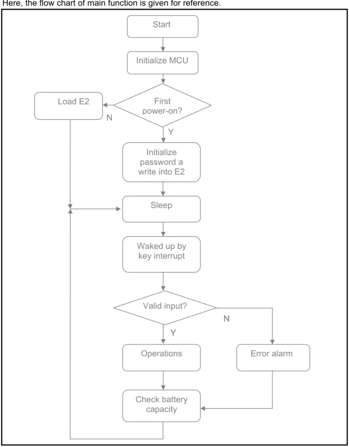
Here, the flow chart of main function is given for reference.
N Y N N Y Y
Figure 6-1: Main Function Figure 6-1: Main Function
Initialize MCU First power-on? Initialize password a write into E2 Valid input? Operations Check battery capacity Sleep Load E2 Waked up by key interrupt Error alarm Start
Electrionic Safe Demo V1.0 Chapter 6 Firmware
When routine starts, initialize the MCU first, then get the information of the Safe: is it a new Safe? If it is, a default password will be set and written into the external EEPROM; otherwise the password will be loaded from EEPROM. Then the Safe enters into sleep mode to save power till a key interrupt comes. In wake-up mode, if password was input, the safe will check the validity. If the input is valid, execute according operation, or Error alarm. Checking the battery capacity is the last function that will be executed every time. In the end, the Safe enters sleep mode.
6.2 Firmware Project
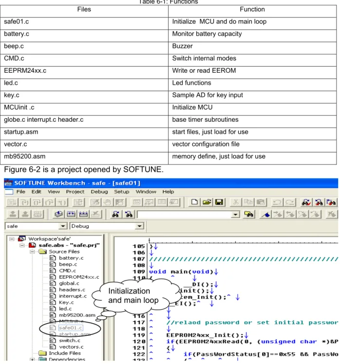
A table was given to explain the function of the main files below.
Table 6-1: Functions
Files Function safe01.c Initialize MCU and do main loop
battery.c Monitor battery capacity
beep.c Buzzer
CMD.c Switch internal modes EEPRM24xx.c Write or read EEROM
led.c Led functions
key.c Sample AD for key input MCUinit .c Initialize MCU
globe.c interrupt.c header.c base timer subroutines
startup.asm start files, just load for use vector.c vector configuration file
mb95200.asm memory define, just load for use
Figure 6-2 is a project opened by SOFTUNE.
Initialization and main loop
Electrionic Safe Demo V1.0 Chapter 7 More Information
7 More
Information
For more information on FUJITSU MB95200 products, please visit following website: English version:
http://www.fujitsu.com/cn/fsp/services/mcu/mb95/application_notes.html Simplified Chinese Version:
http://www.fujitsu.com/cn/fss/services/mcu/mb95/application_notes.html
Electrionic Safe Demo V1.0 Chapter 8 Appendix
8 Appendix
8.1 Tables
Table 5-1: Pin Function ... 12
Table 6-1: Functions ... 16
8.2 Figures
Figure 2-1: Front of Electronic Safe Demo ... 5Figure 4-1: Back of Electronic Safe Demo ... 7
Figure 5-1: System Block Diagram ... 10
Figure 5-2: Electronic Safe ... 11
Figure 5-3: MCU ... 12
Figure 5-4: Power Interface ... 12
Figure 5-5: Key Input ... 13
Figure 5-6: EEPROM ... 13
Figure 5-7: Battery Capacity Monitoring and Alarm ... 14
Figure 6-1: Main Function ... 15