INSTALLATION
START-UP
MAINTENANCE
PARTS
Water Heater Models*
UGC55S-100 / UGC55S-130 / UGC55S-160 / UGC55S-199 UGC80S-100 / UGC80S-130 / UGC80S-160 / UGC80S-199 UGC120S-100 / UGC120S-130 / UGC120S-160 / UGC120S-199
*A suffix of “LP” denotes propane gas
NOTICE:GIANT reserves the right to make product changes or updates without notice and will not be held liable for typographical errors in literature.
NOTE TO CONSUMER: PLEASE KEEP ALL INSTRUCTIONS FOR FUTURE REFERENCE.
This manual must only be used by a qualified heating installer/service technician. Read and understand all instructions in this manual before installing. Perform steps in the order given. Failure to comply will result in substantial property damage, severe personal injury, or death.
IF THE INFORMATION IN THIS MANUAL IS NOT FOLLOWED EXACTLY, A FIRE OR EXPLOSION MAY RESULT, CAUSING PROPERTY DAMAGE, PERSONAL INJURY, OR LOSS OF LIFE. DO NOT STORE GASOLINE OR OTHER FLAMMABLE VAPORS AND LIQUIDS IN THE VICINITY OF THIS OR ANY OTHER APPLIANCE.
WHAT TO DO IF YOU SMELL GAS
Do not try to light any appliance.
Do not touch any electrical switch.
Do not use any phone in your building.
Immediately call your gas supplier from a neighbor’s phone. Follow the gas supplier’s instructions.
If you cannot reach your gas supplier, call the fire department. Installation and service must be provided by a qualified installer, service agency, or the gas supplier.
The following defined terms are used throughout this manual to bring attention to the presence of hazards of various risk levels, or to important product information.
DANGER indicates an imminently hazardous situation which, if not avoided, will result in death or serious injury.
WARNING indicates a potentially hazardous situation which, if not avoided, could result in death or serious injury.
CAUTION indicates a potentially hazardous situation which, if not avoided, may result in minor or moderate injury.
CAUTION used without the safety alert symbol indicates a potentially hazardous situation which, if not avoided, may result in property damage.
FOREWORD
This manual is intended to be used in conjunction with other literature provided with the Phoenix Gas-Fired Water Heater. This includes all related control information. It is important that this manual, all other documents included with this system, and additional publications including the National Fuel Gas Code, ANSI Z223.1-2002, be reviewed in their entirety before beginning any work.
Installation should be made in accordance with the regulations of the Authority Having Jurisdiction, local code authorities, and utility companies which pertain to this type of water heating equipment.
Authority Having Jurisdiction (AHJ) – The Authority Having Jurisdiction may be a federal, state, local government, or individual such as a fire chief, fire marshal, chief of a fire prevention bureau, labor department or health department, building official or electrical inspector, or others having statutory authority. In some circumstances, the property owner or his/her agent assumes the role, and at government installations, the commanding officer or departmental official may be the AHJ.
NOTE: GIANT, Inc. reserves the right to modify product technical specifications and components without prior notice.
FOR THE INSTALLER
This water heater must be installed by qualified and licensed personnel. The installer should be guided by the instructions furnished with the heater, and with local codes and utility company requirements. In the absence of local codes, preference should be given to the National Fuel Gas Code, ANSI Z223.1-2002.
INSTALLATIONS MUST COMPLY WITH:
Local, state, provincial, and national codes, laws, regulations and ordinances.
The latest version of the National Fuel Gas Code, ANSI Z223.1, from American Gas Association Laboratories, 8501 East Pleasant Valley Road, Cleveland, OH 44131.
In Canada – CGA No. B149 (latest version), from Canadian Gas Association Laboratories, 55 Scarsdale Road, Don Mills, Ontario, Canada M3B 2R3. Also, Canadian Electrical Code C 22.1, from Canadian Standards Association, 5060 Spectrum Way, Suite 100, Mississauga, Ontario, Canada L4W 5N6.
Code for the installation of Heat Producing Appliances (latest version), from American Insurance Association, 85 John Street, New York, NY 11038.
The latest version of the National Electrical Code, NFPA No. 70.
NOTE: The gas manifold and controls met safe lighting and other performance criteria when undergoing tests specified in ANSI Z21.10.3 – latest edition.
This manual must only be used by a qualified heating installer/service technician. Read and understand all instructions in this manual before installing. Perform steps in the order given. Failure to comply will result in substantial property damage, severe personal injury, or death.
TABLE OF CONTENTS
FOREWORD ... 3
FOR THE INSTALLER... 3
PART 1 – GENERAL SAFETY INFORMATION ... 6
A. PRECAUTIONS ... 6
B. IMPROPER COMBUSTION ... 6
C. GAS ... 6
D. WHEN SERVICING THE HEATER ... 6
E. HEATER WATER... 6
PART 2 – BEFORE YOU START ... 7
A. WHAT’S IN THE BOX ... 7
B. HOW THE HEATER OPERATES ... 7
C. OPTIONAL EQUIPMENT ... 8
PART 3 – PREPARE WATER HEATER LOCATION ... 8
A. BEFORE LOCATING THE HEATER ... 9
B. LEVELING ... 9
C. CLEARANCES FOR SERVICE ACCESS ... 10
D. RESIDENTIAL GARAGE INSTALLATION ... 10
E. EXHAUST VENT AND INTAKE PIPE ... 10
1. DIRECT VENT INSTALLATION OF EXHAUST VENT AND INTAKE PIPE ... 11
2. INDOOR COMBUSTION AIR INSTALLATION IN CONFINED OR UNCONFINED SPACE ... 11
F. PREVENT COMBUSTION AIR CONTAMINATION ... 11
G. REMOVING A HEATER FROM A COMMON VENT SYSTEM ... 12
H. WATER CHEMISTRY ... 13
PART 4 – HEATER PIPING ... 15
A. GENERAL PIPING INFORMATION ... 15
B. SCALDING ... 16
C. TEMPERATURE AND PRESSURE RELIEF VALVE ... 16
D. BACKFLOW PREVENTER ... 16
E. POTABLE EXPANSION TANK ... 16
F. WATER PIPING ... 17
G. AUXILIARY CONNECTIONS ... 17
H. PIPING DIAGRAM ... 18
PART 5 – VENTING, COMBUSTION AIR AND CONDENSATE REMOVAL ... 24
A. GENERAL ... 24
B. APPROVED MATERIALS FOR EXHAUST VENT AND INTAKE PIPE ... 24
C. REQUIREMENTS FOR INSTALLATION IN CANADA ... 25
D. EXHAUST VENT AND INTAKE PIPE LOCATION ... 25
1. DETERMINE EXHAUST VENT LOCATION ... 25
2. DETERMINE INTAKE PIPE LOCATION ... 26
F. LONGER VENT RUNS ... 27
G. EXHAUST VENT AND INTAKE PIPE INSTALLATION ... 28
H. VENTING DRAWINGS ... 28
1. DIRECT VENT INSTALLATION OF EXHAUST VENT AND INTAKE PIPE ... 28
2. VENTING THROUGH AN EXISTING SYSTEM ... 33
3. INDOOR COMBUSTION AIR INSTALLATION IN CONFINED OR UNCONFINED SPACE ... 35
I. CONDENSATE REMOVAL SYSTEM ... 37
PART 6 – WIRING ... 38
A. LINE VOLTAGE INPUT ... 38
B. LINE VOLTAGE CONDENSATE OUTPUT ... 38
C. LOW VOLTAGE OUTDOOR SENSOR INPUT ... 38
D. INTERNAL WIRING DIAGRAM ... 39
PART 7 – GAS CONNECTIONS ... 41
A. GAS PIPING ... 41
B. GAS TABLE ... 41
C. GAS VALVE ... 42
PART 8 – START-UP PROCEDURE ... 43
A. OPERATING INSTRUCTIONS ... 43
B. OVERALL WATER HEATER AND CONTROL OPERATION ... 43
C. STATUS MENU ... 43
D. OUTDOOR RESET ... 44
E. TEST MODE ... 45
F. MAINTENANCE ... 45
PART 9 – SHUTDOWN... 46
A. SHUTDOWN PROCEDURE ... 46
B. VACATION PROCEDURE ... 46
C. FAILURE TO OPERATE ... 46
PART 10 – TROUBLESHOOTING ... 46
A. ERROR CODE ... 46
B. HEATER ERROR ... 46
C. LOCKOUT ... 46
PART 11 - MAINTENANCE ... 51
MAINTENANCE NOTES ... 52
PART 1 – GENERAL SAFETY INFORMATION
A. PRECAUTIONS
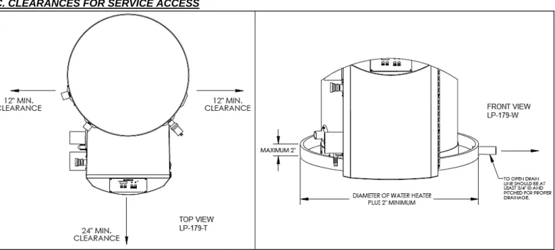
This water heater is for indoor installations only. Clearance to combustible materials: 0” top, bottom, sides and back. Unit must have room for service: 24” (61 cm) front and 12” (30 cm) sides are minimum recommended service clearances. (A combustible door or removable panel is acceptable front clearance.) This water heater has been approved for closet installation, and installation on combustible flooring. Do not install this water heater directly on carpeting. Use only Category IV vent systems.
INSTALLER – Read all instructions in this manual before installing. Perform steps in the order given.
USER – This manual is for use only by a qualified heating installer/service technician. Have this heater serviced/inspected by a qualified service technician annually.
FAILURE TO ADHERE TO THE GUIDELINES ON THIS PAGE AND HAVE THIS HEATER SERVICED/INSPECTED ANNUALLY CAN RESULT IN SUBSTANTIAL PROPERTY DAMAGE, SEVERE PERSONAL INJURY, OR DEATH.
If the heater is exposed to the following, do not operate until all corrective steps have been made by a qualified serviceman: 1. FIRE
2. DAMAGE 3. WATER
Any claims for damage or shortage in shipment must be filed immediately against the transportation company by the consignee.
DO NOT USE THIS APPLIANCE IF ANY PART HAS BEEN SUBMERGED IN WATER. Immediately call a qualified service technician. The appliance MUST BE replaced if it has been submerged. Attempting to operate an appliance that has been submerged could create numerous harmful conditions, such as a potential gas leakage causing a fire and/or explosion, or the release of mold, bacteria, or other harmful particulates into the air. Operating a previously submerged appliance could result in property damage, severe personal injury, or death.
NOTE: Appliance damage due to flood or submersion is considered an Act of God, and IS NOT covered under product warranty.
B. IMPROPER COMBUSTION
Do not obstruct the flow of combustion and ventilating air. Adequate air is necessary for safe operation. Failure to keep the vent and combustion air intake clear of ice, snow, or other debris could result in property damage, serious personal injury, or death.
C. GAS
Should overheating or gas supply fail to shut off, turn off the manual gas control valve to the water heater.
D. WHEN SERVICING THE HEATER
To avoid electric shock, disconnect electrical supply before performing maintenance.
To avoid severe burns, allow heater to cool.
E. HEATER WATER
Do not use petroleum-based cleaning or sealing compounds in a heater system. Gaskets and seals in the system may be damaged. This can result in substantial property damage.
Do not use “homemade cures” or “heater patent medicines”. Substantial property damage, damage to heater, and/or serious personal injury may result.
PART 2 – BEFORE YOU START
A. WHAT’S IN THE BOX
Also included with the heater:
Intake PVC Tee with Screens
Exhaust PVC Coupling with Screens
Temperature and Pressure Relief Valve
Installation Manual
Warranty
Solar Addendum (Solar Models Only)
LP Conversion Kit (Natural Gas Models Only)
B. HOW THE HEATER OPERATES
Modulation Condensing Technology is an intelligent system that delivers highly efficient water heating, while maximizing efficiency by measuring the data parameters of your water heating system. Some of its features are:
Stainless Steel Water Storage Tank
The stainless steel water storage tank has a combustion chamber submerged into the tank water. When the water heater is fired, combustion gases heat the combustion chamber walls, transferring heat directly into the surrounding water. These hot gases are blown into secondary heat exchanger coils, where more heat is transferred into the water, removing even more heat from the gases.
Modulating Combustion System
Modulation during water heating operation is based on tank temperature. The control monitors the system to regulate burner output during operation to match system demand. This increase in efficiency allows for substantial fuel savings.
Gas Valve
The gas valve senses suction from the blower, allowing gas to flow only if the gas valve is energized and combustion air is flowing. Upper Supply Tank Sensor
This sensor monitors the upper portion water temperature (system supply) of the water heater. The control module adjusts the burner firing rate so the outlet water temperature meets the set point.
Lower Return Tank Sensor
This sensor monitors the lower portion of the water heater inlet water temperature (system return). The control module reduces or increases input, depending on how close the water temperature is to the outlet water temperature set point.
Control
The integrated control system monitors upper and lower water temperature and regulates fan speed to regulate the unit’s energy output. This allows the unit to deliver the required amount of heated energy and nothing more.
Burner
Constructed of high grade stainless steel, the burner uses pre-mixed air and gas and provides a wide range of firing rates. Condensate Drain Connection
This is a condensing high efficiency water heater, and therefore has a condensate removal system. Condensate is nothing more than water vapor, derived from combustion products and similar to an automobile when it is initially started. It is very important that the condensate line slopes away from the water heater and down to a suitable inside drain.
If the condensate outlet on the heater is lower than the drain, you must use a condensate removal pump (kit p/n 554200 available from GIANT.) In addition, local authorities may require a condensate neutralizer to neutralize the condensate. Condensate neutralizers are made up of lime crystals, marble or phosphate chips. Neutralizers can be installed in the field by the installer and purchased from GIANT (p/n 7450P-212).
It is also very important not to expose the condensate line to freezing temperatures or any type of blockage. Plastic tubing must be the only material used for the condensate line. Steel, brass, copper or other materials will be subject to corrosion or deterioration. A second vent may be necessary to prevent condensate line vacuum lock on a long horizontal run. Also, an increase in pipe size may be necessary to allow condensate to drain properly. Support of the condensation line may be necessary to avoid blockage of the condensate flow.
Spark Ignition
The burner flame is ignited by applying high voltage to the system spark electrode. This causes a spark from electrode to ground.
C. OPTIONAL EQUIPMENT
Below is a list of optional equipment available from GIANT:
3” (7.6 cm) Stainless Steel Outside Termination Vent Kit (V1000)
4” (10 cm) Stainless Steel Outside Termination Vent Kit (V2000)
2” (5 cm) PVC Concentric Vent Kit (Part # KGAVT0501CVT)
3" (7.6 cm) PVC Concentric Vent Kit (Part # KGAVT0601CVT)
3” (7.6 cm) Polypro Vent Kit (Part # 8400P-001)
3” (7.6 cm) Polypro Pipe (33’ (10 m) length Part # 8400P-002, 49.5’ (15 m) length Part # 8400P-003)
PC Connection Kit (Part # 7250P-320)
Condensate Neutralizer (Part # 7450P-212)
Outdoor Sensor (Part # 7250P-319)
Sanitizer Booster Kit (Part # VSBK-1200)
PART 3 – PREPARE WATER HEATER LOCATION
Carefully consider installation when determining heater location. Please read the entire manual before attempting installation. Failure to properly take factors such as heater venting, piping, condensate removal, and wiring into account before installation could result in wasted time, money, and possible property damage and personal injury.
A. BEFORE LOCATING THE HEATER
Incorrect ambient conditions can lead to damage to the heating system and put safe operation at risk. Ensure that the heater installation location adheres to the information included in this manual. Failure to do so could result in property damage, serious personal injury, or death.
Failure of heater or components due to incorrect operating conditions IS NOT covered by product warranty. 1. Installation Area (Mechanical Room) Operating Conditions
Ensure ambient temperatures are higher than 32oF (0oC) and lower than 104oF (40oC).
Prevent the air from becoming contaminated by the products, places, and conditions listed in this manual, Part 3, Section F.
Avoid continuously high levels of humidity
Never close existing ventilation openings
Ensure a minimum 1” (2.5 cm) clearance around hot water and exhaust vent pipes
The service life of the heater’s exposed metallic surfaces, such as the casing, as well as internal surfaces, such as the heat exchanger, are directly influenced by proximity to damp and salty marine environments. In such areas, higher concentration levels of chlorides from sea spray coupled with relative humidity can lead to degradation of the heat exchanger and other heater components. In these environments, heaters must not be installed using direct vent systems which draw outdoor air for combustion. Such heaters must be installed using room air for combustion. Indoor air will have a much lower relative humidity and, hence, potential corrosion will be minimized.
This heater is certified for indoor installations only. Do not install the heater outdoors. Failure to install this heater indoors could result in substantial property damage, severe personal injury, or death.
2. Check for nearby connections to:
System water piping
Venting connections
Gas supply piping
Electrical power
Condensate drain
3. Check area around heater. Remove any combustible materials, gasoline, and other flammable liquids.
Failure to keep heater area clear and free of combustible materials, liquids, and vapors can result in substantial property damage, severe personal injury, or death.
4. Gas control system components must be protected from dripping water during operation and service. 5. If the heater is to replace an existing heater, check for and correct any existing system problems, such as:
System leaks
Location that could cause the system and heater to freeze and leak.
Incorrectly-sized expansion tank
6. Clean and flush system when reinstalling a heater.
NOTE: When installing in a zero clearance location, it may not be possible to read or view some product labeling. It is recommended to make note of the heater model and serial number.
B. LEVELING
In order for the condensate to properly flow out of the collection system, the area where you locate the heater must be level. Location must also fully support the weight of the filled water heater.
C. CLEARANCES FOR SERVICE ACCESS
Figure 1: Minimum Service Clearances
NOTE: If you do not provide the minimum clearances shown in Figure 1, it might not be possible to service the heater without removing it from the space.
The space must be provided with combustion/ventilation air openings correctly sized for all other appliances located in the same space as the heater. The heater cover must be securely fastened to prevent the heater from drawing air form the heater room. This is particularly important if the heater is in a room with other appliances. Failure to comply with the above warnings could result in substantial property damage, severe personal injury, or death.
D. RESIDENTIAL GARAGE INSTALLATION
PRECAUTIONSIf the heater is located in a residential garage, per ANSI Z223.1:
Mount the bottom of the heater a minimum of 18” (46 cm) above the floor of the garage, to ensure the burner and ignition devices are well off the floor.
When raising the heater, fully support the entire bottom of the water heater.
Locate or protect the heater so it cannot be damaged by a moving vehicle.
E. EXHAUST VENT AND INTAKE PIPE
The heater is rated ANSI Z21.10.3 Category IV (pressurized vent, likely to form condensate in the vent) and requires a special vent system designed for pressurized venting.
NOTE: The venting options described here (and further detailed in Venting, Part 5 in this manual) are the lone venting options approved for this water heater. Failure to vent the water heater in accordance with the provided venting instructions will void the warranty.
Failure to vent the water heater properly will result in serious personal injury or death.
Vents must be properly supported. Heater exhaust and intake connections are not designed to carry heavy weight. Vent support brackets must be within 1’ (30 cm) of the heater and the balance at 4’ (1.2 m) intervals. Heater must be readily accessible for visual inspection for the first 3’ (91 cm) from the heater.
1. DIRECT VENT INSTALLATION OF EXHAUST VENT AND INTAKE PIPE
If installing a direct vent option, combustion air must be drawn from the outdoors directly into the water heater intake, and exhaust must terminate outside. There are three basic direct vent options detailed in this manual:
1. Side Wall Venting 2. Roof Venting 3. Unbalanced Venting
Be sure to locate the heater such that the exhaust vent and intake piping can be routed through the building and properly terminated. Different vent terminals can be used to simplify and eliminate multiple penetrations in the building structure (refer to the Venting Section). The exhaust vent and intake piping lengths, routing and termination methods must all comply with the methods and limits given in the Venting section, Part 5 of this manual.
When installing a combustion air intake from outdoors, care must be taken to utilize uncontaminated combustion air. To prevent combustion air contamination, see Table 1: Contaminant Table.
2. INDOOR COMBUSTION AIR INSTALLATION IN CONFINED OR UNCONFINED SPACE
This heater requires fresh, uncontaminated air for safe operation and must be installed in a mechanical room where there is adequate combustion and ventilating air. NOTE: To prevent combustion air contamination, see Table 1: Contaminant Table.
Combustion air from the indoor space can be used if the space has adequate area or when air is provided through a duct or louver to supply sufficient combustion air based on the water heater input. Never obstruct the supply of combustion air to the water heater. If the water heater is installed in areas where indoor air is contaminated (see Table 1) it is imperative that the water heater be installed as direct vent so that all combustion air is taken directly from the outdoors into the water heater intake connection.
Unconfined space is space with volume greater than 50 cubic feet per 1,000 Btu/hour (4.8 cubic meters per kW) of the total input rating of all fuel-burning appliances installed in that space. Rooms connected directly to this space, through openings not furnished with doors, are considered part of the space. See
Figure , p. 36 for details.
Confined space is space with volume less than 50 cubic feet per 1,000 Btu/hour (4.8 cubic meters per kW) of the total input rating of all fuel-burning appliances installed in that space. Rooms connected directly to this space, through openings not furnished with doors, are considered part of the space.
When drawing combustion air from inside a conventionally constructed building to a confined space, such space should be provided with two permanent openings: one located 6” (15 cm) below the space ceiling, the other 6” (15 cm) above the space floor. Each opening should have a free area of one square inch per 1,000 Btu/hr (22 cm2/kW) of the total input of all appliances in the space, but not less than 100 square inches (645 cm2).
If the confined space is within a building of tight construction, air for combustion must be obtained from the outdoors as outlined in the Venting section, Part 5 of this manual.
When drawing combustion air from the outside into the mechanical room, care must be taken to provide adequate freeze protection.
Do not attempt to vent this water heater by any means other than those described in this manual. Doing so will void the warranty, and may result in severe personal injury or death.
Failure to provide an adequate supply of fresh combustion air can cause poisonous flue gases to enter living space, resulting in severe personal injury or death.To prevent combustion air contamination, see Table 1.
F. PREVENT COMBUSTION AIR CONTAMINATION
Install intake piping for the heater as described in the Venting Section. Do not terminate exhaust in locations that can allow contamination of intake air.
Ensure that the intake air will not contain any of the contaminants below. Contaminated air will damage the heater, resulting in possible substantial property damage, severe personal injury, or death. For example, do not pipe intake near a swimming pool. Also, avoid areas subject to exhaust fumes from laundry facilities. These areas always contain contaminants.
PRODUCTS TO AVOID AREAS LIKELY TO HAVE CONTAMINANTS
Spray cans containing fluorocarbons Dry cleaning/laundry areas and establishments
Permanent wave solutions Swimming pools
Chlorinated waxes/cleaners Metal fabrication plants Chlorine-based swimming pool chemicals Beauty shops
Calcium chloride used for thawing Refrigeration repair shops Sodium chloride used for water softening Photo processing plants
Refrigerant leaks Auto body shops
Paint or varnish removers Plastic manufacturing plants
Hydrochloric or Muriatic acid Furniture refinishing areas and establishments
Cements and glues New building construction
Antistatic fabric softeners used in clothes dryers Remodeling areas Chlorine-type bleaches, laundry detergents, and cleaning solvents Garages and workshops Adhesives used to fasten building products
Table 1: Contaminant Table
G. REMOVING A HEATER FROM A COMMON VENT SYSTEM
Do not install the heater into a common vent with any other appliance. This will cause flue gas spillage or appliance malfunction, resulting in possible substantial property damage, severe personal injury, or death.
Failure to follow all instructions can result in flue gas spillage and carbon monoxide emissions, causing severe personal injury or death. When removing an existing heater, follow the steps below.
1. Seal any unused openings in the common venting system.
2. Visually inspect the venting system for proper size and horizontal pitch to determine if there is blockage, leakage, corrosion or other deficiencies that could cause an unsafe condition.
3. If practical, close all building doors, windows and doors between the space in which the water heater remains connected to the common venting system and other spaces in the building. Turn on clothes dryers and any appliances not connected to the common venting system. Turn on any exhaust fans, such as range hoods and bathroom exhausts, at maximum speed. Do not operate a summer exhaust fan. Close all fireplace dampers.
4. Place in operation the appliance being inspected. Follow the lighting instructions. Adjust the thermostat so the appliance will operate continuously.
5. Test for spillage at the draft hood relief opening after 5 minutes of main burner operation. Use the flame of a match or candle.
6. After it has been determined that each appliance remaining connected to common venting system properly vents when tested as outlined, return doors, windows, exhaust fans, fireplace dampers and any other gas burning appliance to their previous condition of use. 7. Any improper operation of the common venting system should be corrected to conform to the National Fuel Gas Code, ANSI Z223.1. When resizing any portion of the common venting system, the system should approach the minimum size as determined using the appropriate tables in Appendix G in the National Fuel Gas Code, ANSI Z 223.1.
NOTE: DAMAGE TO THE HEATER CAUSED BY EXPOSURE TO CORROSIVE VAPORS IS NOT COVERED BY WARRANTY. (Refer to the limited warranty for complete terms and conditions).
H. WATER CHEMISTRY
Chemical imbalance of the water supply may affect efficiency and cause severe damage to the water heater and associated equipment. GIANT recommends having water quality professionally analyzed to determine whether it is necessary to install a water softener. It is important that the water chemistry on both the domestic hot water and central heating sides are checked before installing the water heater, as water quality will affect the reliability of the system. Failure of a heat exchanger due to lime scale build-up on the heating surface, low pH, or other chemical imbalance IS NOT covered by the warranty.
Operating temperatures above 135oF (57oC) will further accelerate the build-up of lime scale on the heating surface and may shorten the service life of the water heater. Failure of a heat exchanger due to lime scale build-up on the heating surface, low pH, or other chemical imbalance IS NOT covered by the warranty.
Outlined below are water quality parameters which need to be met in order for the system to operate efficiently for many years. Water Hardness
Water hardness is mainly due to the presence of calcium and magnesium salts dissolved in water. The concentration of these salts is expressed in mg/L, ppm, or grains per gallon as a measure of relative water hardness. ‘‘Grains per gallon’’ is the common reference measurement used in the U.S. water heater industry. Hardness expressed as mg/L or ppm may be divided by 17.1 to convert to grains per gallon. Water may be classified as very soft, slightly hard, moderately hard, or hard based on its hardness number. The minerals in the water precipitate out as the water is heated and cause accelerated lime scale accumulation on a heat transfer surface. This lime scale build-up may result in premature failure of the heat exchanger. Operating temperatures above 135oF (57oC) will further accelerate the build-up of lime scale on the heating surface and may shorten the service life of the water heater.
Water that is classified as hard and very hard must be softened to avoid heat exchanger failure. See below for further information about water hardness. CLASSIFICATION MG/L OR PPM GRAINS/GAL Soft 0 – 17.1 0 - 1 Slightly Hard 17.1 – 60 1 – 3.5 Moderately Hard 60 – 120 3.5 – 7.0 Hard 120 – 180 7.0 – 10.5
Very Hard 180 and over 10.5 and over
If the hardness of the water exceeds the maximum level of 7 grains per gallon, water should be softened to a hardness level no lower than 5 grains per gallon. Water softened as low as 0 to 1 grain per gallon may be under-saturated with respect to calcium carbonate, resulting in water that is aggressive and corrosive.
pH of Water
pH is a measure of relative acidity, neutrality or alkalinity. Dissolved minerals and gases affect water pH. The pH scale ranges from 0 to 14. Water with a pH of 7.0 is considered neutral. Water with a pH lower than 7 is considered acidic. Water pH higher than 7 is considered alkaline. A neutral pH (around 7) is desirable for most potable water applications. Corrosion damage and heater failures resulting from water pH levels of lower than 6 or higher than 8 ARE NOT covered by the warranty. The ideal pH range for water used in a storage tank or a water heater system is 7.2 to 7.8.
Total Dissolved Solids
Total Dissolved Solids (TDS) is a measurement of all minerals and solids dissolved in a water sample. The concentration of total dissolved solids is usually expressed in parts per million (ppm).
Water with a high TDS concentration will greatly accelerate lime and scale formation in the hot water system. Most high TDS concentrations precipitate out of the water when heated. This can generate a scale accumulation on the heat transfer surface that will greatly reduce the service life of a water heater. This scale accumulation can also impede the ability of the heat exchanger to transfer heat into the water. A heat exchanger damaged or blocked by lime/scale accumulation must be replaced.
The manufacturer of the water heater has no control of water quality, especially TDS levels in your system. Total dissolved solids in excess of 2,000 ppm will accelerate lime and scale formation in the heat exchanger. Heat exchanger failure due to total dissolved solids in excess of 2,000 ppm is a non-warrantable condition. Failure of a water heater due to lime scale build up on the heating surface IS NOT covered by the warranty.
Hardness: 7 grains Chloride levels: 100 ppm pH levels: 6-8
TDS: 2,000 ppm Sodium: 20 MGL
Figure 3 –
*All dimensions are approximate – A suffix of “LP” denotes propane gas - LP-179-BUNCRATING HEATER – Any claims for damage or shortage in shipment must be filed immediately against the transportation company by the consignee.
COLD WEATHER HANDLING – If the heater has been stored in a very cold location (BELOW 0oF (-18oC)) before installation, handle with care until the plastic components come to room temperature.
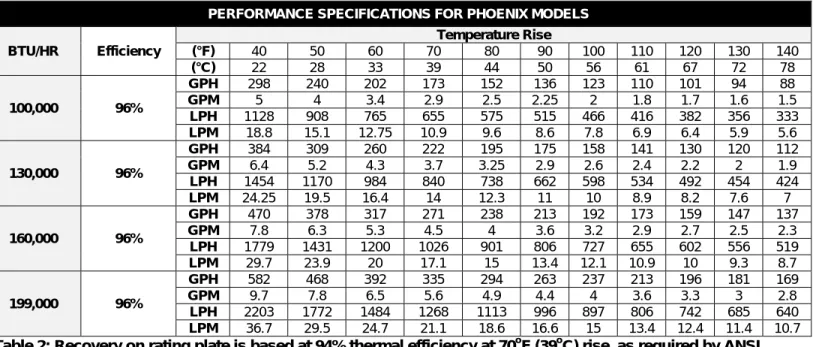
Remove all sides of the shipping crate to allow the heater to be lifted into its installation location. PERFORMANCE SPECIFICATIONS FOR PHOENIX MODELS
BTU/HR Efficiency Temperature Rise (°F) 40 50 60 70 80 90 100 110 120 130 140 (°C) 22 28 33 39 44 50 56 61 67 72 78 100,000 96% GPH 298 240 202 173 152 136 123 110 101 94 88 GPM 5 4 3.4 2.9 2.5 2.25 2 1.8 1.7 1.6 1.5 LPH 1128 908 765 655 575 515 466 416 382 356 333 LPM 18.8 15.1 12.75 10.9 9.6 8.6 7.8 6.9 6.4 5.9 5.6 130,000 96% GPH 384 309 260 222 195 175 158 141 130 120 112 GPM 6.4 5.2 4.3 3.7 3.25 2.9 2.6 2.4 2.2 2 1.9 LPH 1454 1170 984 840 738 662 598 534 492 454 424 LPM 24.25 19.5 16.4 14 12.3 11 10 8.9 8.2 7.6 7 160,000 96% GPH 470 378 317 271 238 213 192 173 159 147 137 GPM 7.8 6.3 5.3 4.5 4 3.6 3.2 2.9 2.7 2.5 2.3 LPH 1779 1431 1200 1026 901 806 727 655 602 556 519 LPM 29.7 23.9 20 17.1 15 13.4 12.1 10.9 10 9.3 8.7 199,000 96% GPH 582 468 392 335 294 263 237 213 196 181 169 GPM 9.7 7.8 6.5 5.6 4.9 4.4 4 3.6 3.3 3 2.8 LPH 2203 1772 1484 1268 1113 996 897 806 742 685 640 LPM 36.7 29.5 24.7 21.1 18.6 16.6 15 13.4 12.4 11.4 10.7
Table 2: Recovery on rating plate is based at 94% thermal efficiency at 70
oF (39
oC) rise, as required by ANSI
PERFORMANCE EQUATIONS
Rated Input x .9
GPM = Temp Rise (oF) x 500 GPH = GPM x 60
PART 4 – HEATER PIPING
Failure to follow the instructions in this section WILL VOID the warranty and may result in property damage, serious injury, or death.
A. GENERAL PIPING INFORMATION
Use two (2) wrenches when tightening water piping at heater. Use one wrench to prevent the heater return or supply line from turning. Failure to prevent piping connections from turning could cause damage to heater components.
The heater control module uses temperature sensors to provide both high limit protection and modulating temperature control. The control module also provides low water protection by sensing the water level in the tank. Some codes/jurisdictions may require additional external controls.
Never use dielectric unions or galvanized steel fittings when connecting to a stainless steel storage tank or heater. Use only copper or brass fittings. Teflon thread sealant must be used on all connections.
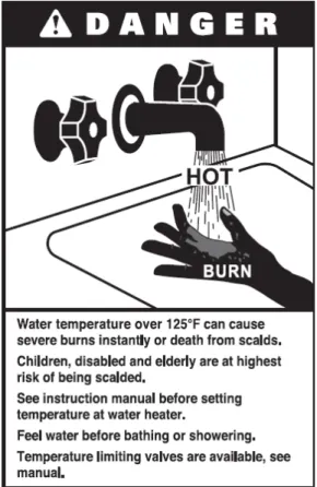
B. SCALDING
This heater can deliver scalding water. Be careful whenever using hot water to avoid scalding injury. Certain appliances, such as dishwashers and automatic clothes washers may require increased water temperature. By setting the thermostat on this heater to obtain the increased water temperature required by these appliances, you may create the potential for scald injury.
To protect against injury, you should install a mixing valve in the water system. This valve will reduce point of discharge temperature by mixing cold and hot water in branch supply lines. Such valves are available from your local plumbing supplier.
Table 3 details the relationship of water temperature and time with regard to scald injury and may be used as a guide in determining the safest water temperature for your applications.
C. TEMPERATURE AND PRESSURE RELIEF VALVE
To avoid water damage or scalding due to relief valve operation:
Discharge line must be connected to relief valve outlet and run to a safe place of disposal. Terminate the discharge line in a manner that will prevent possibility of severe burns or property damage should the relief valve discharge.
Discharge line must be as short as possible and the same size as the valve discharge connection throughout its entire length.
Discharge line must pitch downward from the valve and terminate at least 6” (15 cm) above the floor drain, making discharge clearly visible.
The discharge line shall terminate plain, not threaded, with a material serviceable for temperatures of 375oF (191oC) or greater.
Do not pipe discharge to any location where freezing could occur.
No shutoff valve may be installed between the relief valve and heater or in the discharge line. Do not plug or place any obstruction in the discharge line.
Test the operation of the relief valve after filling and pressurizing the system by lifting the lever. Make sure the valve discharges freely. If the valve fails to operate correctly, immediately replace with a new properly rated relief valve.
Test T&P valve at least once annually to ensure the waterway is clear. If valve does not operate, turn the heater “off” and call a plumber immediately.
Take care whenever operating relief valve to avoid scalding injury or property damage.
FAILURE TO COMPLY WITH THE ABOVE GUIDELINES COULD RESULT IN FAILURE OF RELIEF VALVE OPERATION, RESULTING IN POSSIBILITY OF SUBSTANTIAL PROPERTY DAMAGE, SEVERE PERSONAL INJURY, OR DEATH.
Do not thread a cap or plug into the relief valve under any circumstances! Explosion and property damage, serious injury, or death may result.
D. BACKFLOW PREVENTER
Use a backflow preventer specifically designed for water heater installations. This valve should be installed on the cold water fill supply line per local codes.
E. POTABLE EXPANSION TANK
A potable hot water expansion tank is required to offset heated water expansion. In most city plumbing systems, the water meter has a no return or back flow device built into the system to prevent back flowing of water into city mains. Some local codes require back flow preventers on all incoming water supplies. The hot water expansion tank must be listed for potable water use. The expansion tank should be located on the cold inlet piping close to the water heater.
Table 3
APPROXIMATE TIME / TEMPERATURE RELATIONSHIPS IN SCALDS 120oF (49oC) More than 5 minutes
125oF (52oC) 1 ½ to 2 minutes 130oF (54oC) About 30 seconds 135oF (57oC) About 10 seconds 140oF (60oC) Less than 5 seconds 145oF (63oC) Less than 3 seconds 150oF (66oC) About 1 ½ seconds 155oF (68oC) About 1 second
EXPANSION TANK AND MAKE-UP WATER
1. Ensure that the expansion tank is sized to correctly handle heater and system water volume and temperature.
Undersized expansion tanks cause system water to be lost from the relief valve, causing make-up water to be added. Eventual heater failure can result due to excessive make-up water addition. SUCH FAILURE IS NOT COVERED BY WARRANTY.
2. The expansion tank must be located as shown in the Heater Piping Details, or following recognized design methods. See expansion tank manufacturer’s instructions for details.
The expansion tank must be suitable for hot potable water.
F. WATER PIPING
Never use dielectric unions or galvanized steel fittings on any domestic water or auxiliary connections. Use only copper or brass fittings. Thread sealant must be used on all connections.
The domestic water connections must be installed in accordance to all local and national plumbing codes, or any applicable standard which prevails. The inlet and outlet ports are 1" (2.5 cm) on 55 gallon (208 L) models, and 1 ½” (3.8 cm) on 80 (303 L) and 119 gallon (451 L) models.
On the cold inlet, install a 1" (2.5 cm) brass tee on 55 gallon (208 L) models, or a 1 ½" (3.8 cm) tee on 80 (303 L) and 119 gallon (451 L) models. On the run of the 1" (2.5 cm) brass tee, install a brass drain cock or equivalent with pipe sealant compound. In the branch of the 1" (2.5 cm) or a 1 ½" (3.8 cm) brass tee, install a copper male adapter to match your copper plumbing system. For convenience, you may install a sweat shut off valve and a union in the cold inlet piping to ease future servicing. If there is a back flow preventer or any type of a no return valve in the system, you must install an additional tee here, suitable for a potable hot water expansion tank. In the hot outlet, install a suitable adapter to match the copper tubing of the plumbing system. A thermal trap or heat trap loop may be installed here to provide additional energy savings and prevent the thermal siphoning of domestic hot water.
G. AUXILIARY CONNECTIONS
The auxiliary connections are additional connections for air handlers, plate exchangers, or other devices that supply hot water. These connections must be installed in accordance with all local and national codes or any applicable standard that prevails. Auxiliary connections are 1" (2.5 cm) on all models. Never use dielectric unions or galvanized steel fittings. Use only copper or brass fittings. Sealant must be used on all connections. The top port is the supply outlet and the bottom port is the return inlet.
Never connect auxiliary connections to any system that uses glycol or other solutions formulated for hydronic systems. These auxiliary connections are to be used only in a potable water system. Failure to follow this warning could result in serious injury or death.
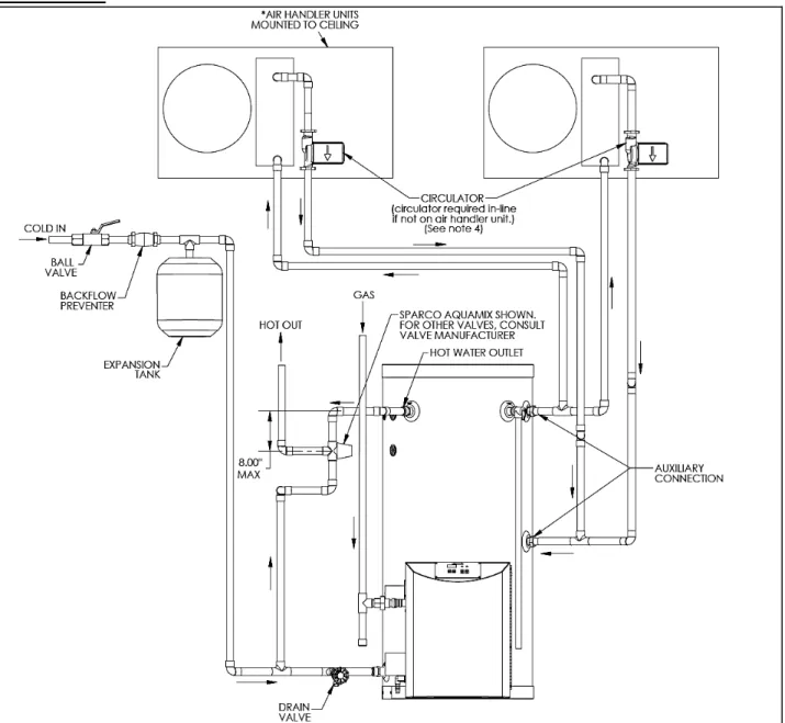
H. PIPING DIAGRAM
Figure 4: Phoenix With Air Handler
NOTES:
1. Minimum pipe size should match unit connection size. Upsize pipe accordingly if greater flow is required.
2. A thermal expansion tank suitable for potable water must be sized and installed within this piping system between the backflow preventer and the cold water inlet.
3. Gas line must be rated to the unit maximum input capacity. Unit must have 10’ (3 m) of pipe after gas regulator. 4. All circulators should have an integral flow check.
5. Check with air handler manufacturer for proper sizing.
6. This drawing is meant to demonstrate system piping only. The installer is responsible for all equipment and detailing required by local codes.
NOTES FOR AIR HANDLER APPLICATION:
1. ALL WATER PIPING MUST BE INSULATED.
2. YOU MUST INSTALL A VACUUM RELIEF VALVE PER 248 CMR.
NOTE: THIS DRAWING IS MEANT TO DEMONSTRATE SYSTEM PIPING ONLY. THE INSTALLER IS RESPONSIBLE FOR ALL EQUIPMENT AND DETAILING REQUIRED BY LOCAL CODES.
An ASSE 1017 thermostatic mixing valve MUST be installed when using outdoor reset. Failure to do so could result in substantial property damage, serious injury, or death.
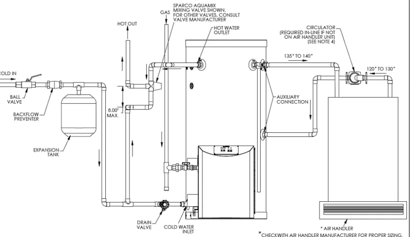
Figure 5: Phoenix with Air Handler on Side
NOTES:
1. Minimum pipe size should match unit connection size. Upsize pipe accordingly if greater flow is required.
2. A thermal expansion tank suitable for potable water must be sized and installed within this piping system between the backflow preventer and the cold water inlet.
3. Gas line must be rated to the unit maximum input capacity. Unit must have 10’ (3 m) of pipe after gas regulator. 4. All circulators should have an integral flow check.
5. Check with air handler manufacturer for proper sizing.
6. This drawing is meant to demonstrate system piping only. The installer is responsible for all equipment and detailing required by local codes.
NOTES FOR AIR HANDLER APPLICATION: 1. ALL WATER PIPING MUST BE INSULATED.
2. YOU MUST INSTALL A VACUUM RELIEF VALVE PER 248 CMR.
NOTE: THIS DRAWING IS MEANT TO DEMONSTRATE SYSTEM PIPING ONLY. THE INSTALLER IS RESPONSIBLE FOR ALL EQUIPMENT AND DETAILING REQUIRED BY LOCAL CODES.
An ASSE 1017 thermostatic mixing valve MUST be installed when using outdoor reset. Failure to do so could result in substantial property damage, serious injury, or death.
Figure 6: Reverse Manifold and Piping Diagram for Phoenix - LP-179-N
NOTES:
1. Minimum pipe size should match unit connection size. Upsize pipe accordingly if greater flow is required.
2. A thermal expansion tank suitable for potable water must be sized and installed within this piping system between the backflow preventer and the cold water inlet.
3. Gas line must be rated to the unit maximum input capacity. Unit must have 10’ (3 m) of pipe after gas regulator. 4. All circulators should have an integral flow check.
5. Check with air handler manufacturer for proper sizing.
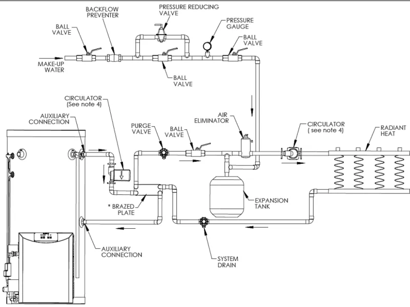
Figure 7: Closed Loop with Radiant Heating - LP-179-U
NOTES:
1. Minimum pipe size should match unit connection size. Upsize pipe accordingly if greater flow is required.
2. A thermal expansion tank suitable for potable water must be sized and installed within this piping system between the backflow preventer and the cold water inlet.
3. Gas line must be rated to the unit maximum input capacity. Unit must have 10’ (3 m) of pipe after gas regulator. 4. All circulators should have an integral flow check.
5. Check with brazed plate manufacturer for correct plate connections and orientation.
6. This drawing is meant to demonstrate system piping only. The installer is responsible for all equipment and detailing required by local codes.
Figure 8: Phoenix With Storage Tank
NOTES:
1. Minimum pipe size should match unit connection size. Upsize pipe accordingly if greater flow is required.
2. A thermal expansion tank suitable for potable water must be sized and installed within this piping system between the backflow preventer and the cold water inlet.
3. Gas line must be rated to the unit maximum input capacity. Unit must have 10’ (3 m) of pipe after gas regulator. 4. All circulators should have an integral flow check.
5. Drains and check valve between unit and storage tank will assist in purging air from system.
6. This drawing is meant to demonstrate system piping only. The installer is responsible for all equipment and detailing required by local codes.
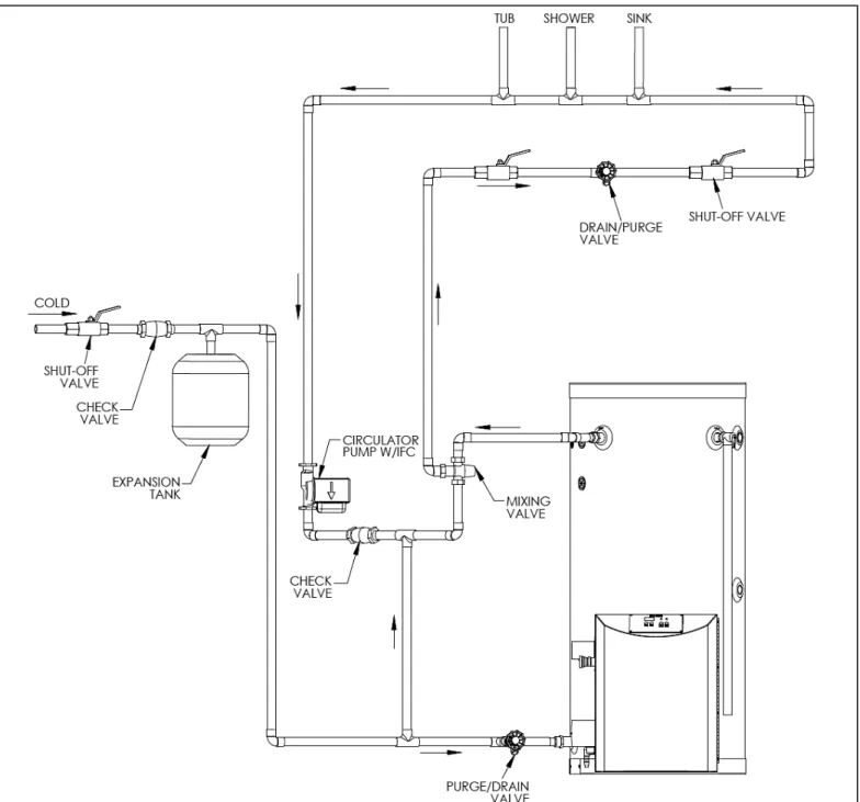
Figure 9: Phoenix with Recirculation Line and Thermostatic Mixing Valve Piping
NOTES:
1. Minimum pipe size should match unit connection size. Upsize pipe accordingly if greater flow is required.
2. A thermal expansion tank suitable for potable water must be sized and installed within this piping system between the backflow preventer and the cold water inlet.
3. Gas line must be rated to the unit maximum input capacity. Unit must have 10’ (3 m) of pipe after gas regulator. 4. All circulators should have an integral flow check.
5. Drains and check valve between unit and storage tank will assist in purging air from system.
6. This drawing is meant to demonstrate system piping only. The installer is responsible for all equipment and detailing required by local codes.
An ASSE 1017 thermostatic mixing valve MUST be installed when using outdoor reset. Failure to do so could result in substantial property damage, serious injury, or death.
PART 5 – VENTING, COMBUSTION AIR AND CONDENSATE REMOVAL
The heater must be vented as detailed in this Venting Section. Ensure exhaust vent and intake piping complies with these instructions regarding vent system. Inspect finished exhaust vent and intake piping thoroughly to ensure all joints are well secured, airtight, and comply with all applicable code requirements, as well as with the instructions provided in this manual. Failure to properly install the vent system will result in severe personal injury or death.
A. GENERAL
This heater is certified as a “Category IV” appliance, and requires a special venting system. The vent system will operate with a positive pressure in the pipe. Exhaust gases must be piped directly outdoors using the vent materials and rules outlined in these instructions. Do not connect vent connectors serving appliances vented by natural draft into any portion of mechanical draft systems operating under positive pressure. Follow the venting instructions below carefully. Failure to do so will result in substantial property damage, severe personal injury, or death.
1. Installation should be made in accordance with the regulations of the Authority Having Jurisdiction, local code authorities, and utility companies which pertain to this type of water heating equipment.
2. Install the venting system in accordance with these instructions and with the National Fuel Gas Code, ANSI Z223.1/NFPA 54, CAN/CGA B149, and/or applicable provisions of local building codes.
3. This water heater must be vented with materials, components, and systems listed and approved for Category IV appliances.
Exhaust vent and intake pipes are to be piped separately. This heater cannot share a common exhaust or intake with multiple appliances. Failure to follow this instruction will result in substantial property damage, severe personal injury, or death.
NOTE: To avoid contamination often contained in indoor air, it is best to pipe all intake combustion air directly to the outdoors.
NOTE: If exhaust vent pipe system passes through an unheated space, such as an alcove or attic, the space must be heated or the pipe must be insulated. The insulation must have an R value sufficient to prevent freezing of the condensate.
Improper seating of vent pipe gaskets can cause eventual gasket failure and exhaust gas leakage. Ensure the exhaust vent pipe is properly beveled and seated before insertion into the flue adapter. Failure to do so could result in property damage, severe personal injury, or death.
Due to the extreme flammability of most glue, cements, solvents, and primers used to join plastic exhaust vent and intake pipes, explosive solvent vapors must be cleared from all vent piping before start-up. Avoid using excess cement or primer, as this may pool in the vent pipes. Vent assemblies should be allowed to cure for a period of at least eight (8) hours before powering a connected appliance. Failure to follow these instructions will result in substantial property damage, severe personal injury, or death. It is the installers’ responsibility to understand the hazards associated with explosive solvents and take the necessary precautions to avoid these risks.
B. APPROVED MATERIALS FOR EXHAUST VENT AND INTAKE PIPE
APPROVED EXHAUST VENT AND INTAKE PIPE MATERIAL
Item Material Standards for Installation in:
United States Canada
Exhaust vent or Intake pipe and fittings
PVC schedule 40/80 ANSI/ASTM D1785 PP, CPVC, and PVC venting must be ULC-S636 Certified.
IPEX is an approved manufacturer in Canada, supplying vent material listed to
ULC-S636.
PVC-DWV* ANSI/ASTM D2665
CPVC schedule 40/80 ANSI/ASTM F441
Polypropylene ULCS636 Stainless Steel AL29-4C Certified for Category IV and
direct vent appliance venting
Certified for Category IV and direct vent appliance venting
Pipe cement/primer PVC ANSI/ASTM D2564 IPEX System 636 Cements &
Primers
CPVC ANSI/ASTM F493
The exhaust and intake components installed with this heater must be used for near heater piping BEFORE transitioning to the approved materials listed above. DO NOT REMOVE these installed components. Doing so WILL VOID heater warranty.
PVC/CPVC pipe and fittings of the same diameter are considered interchangeable.
DO NOT use Foam Core Pipe in any portion of the exhaust piping from this water heater.
DO NOT connect PVC/CPVC to PP without an approved vent connector.
When installing AL29-4C vent piping, install a PVC-to-stainless adapter at the heater vent connection, and at the termination when using an GIANT PVC termination kit. DO NOT mix AL-29-4C piping from different manufacturers unless using adapters specifically designed for the purpose by the manufacturer.
*PVC-DWV for air intake applications ONLY.
Failure to follow these directions will result in substantial property damage, severe personal injury, or death.
DO NOT mix components from different venting systems. The vent system could fail, causing leakage of flue products into the living space. Use only the approved pipe and fitting materials, and primer and cement specifically designed for the material used, as listed in Table 4. Failure to do so could result in property damage, severe personal injury, or death.
Exhaust vent adaptors are not designed as load-bearing devices, and must not be used to support exhaust vent piping. All vent pipes must be properly connected, supported, and the exhaust must be pitched a minimum of ¼” (6.3 mm) per foot back to the heater to allow drainage of condensate. Failure to properly support vent piping and follow the information in this statement could result in product damage, severe personal injury, or death.
NOTE: The use of double-wall vent or insulated material for the combustion air inlet pipe is recommended in cold climates to prevent the condensation of airborne moisture in the incoming combustion air.
C. REQUIREMENTS FOR INSTALLATION IN CANADA
1. Installations must be made with a vent pipe system certified to ULC-S636. IPEX is an approved vent manufacturer in Canada supplying vent material listed to ULC-S636. Additionally you may use AL29-4C stainless steel venting to comply with Canadian requirements.
2. The first three (3) feet (91 cm) of vent pipe from the water heater flue outlet must be readily accessible for visual inspection. 3. The components of the certified vent system must not be interchanged
with other vent systems or unlisted pipe / fittings.
Cellular foam core piping may be used on air inlet piping only.
You must not use “B” vent in an exhaust application. “B” vent is for intake applications ONLY. Using “B” vent in an exhaust application will result in serious injury or death.
D. EXHAUST VENT AND INTAKE PIPE LOCATION
1. DETERMINE EXHAUST VENT LOCATION
a. The vent piping for this water heater is approved for zero clearance to combustible construction.
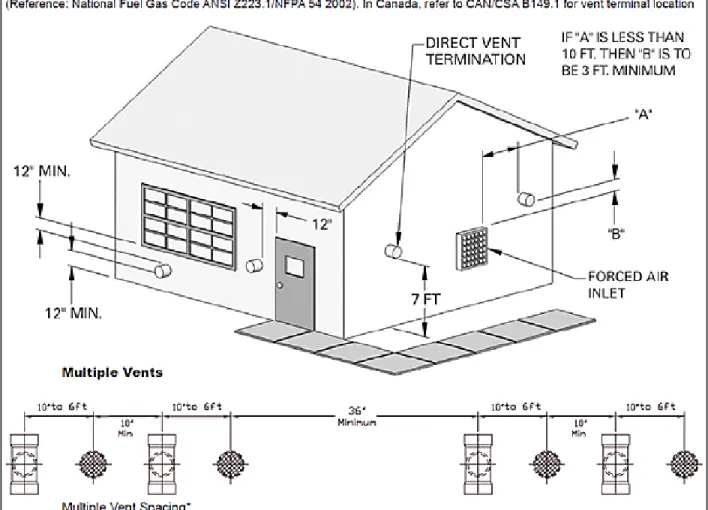
b. See illustration within this section of clearances for location of exit terminals of direct-vent venting systems.
c. This water heater vent system shall terminate at least three (3) feet (91 cm) above any forced air intake located within ten (10) feet (3 m). Note: this does not apply to the combustion air intake of a direct-vent appliance.
d. Provide a minimum of one (1) foot (30 cm) distance from any door, operable window, or gravity intake into any building. e. Provide a minimum of one (1) foot (30 cm) clearance from the bottom of the exhaust above the expected snow accumulation level. Snow removal may be necessary to maintain clearance.
f. Provide four (4) feet (1.2 m) horizontal clearance from electrical meters, gas meters, gas regulators, relief equipment, exhaust fans and inlets. In no case shall the exit terminal be above or below the aforementioned equipment unless the four (4) feet (1.2 m) horizontal distance is maintained.
g. When adjacent to a public walkway, locate exit terminal at least seven (7) feet (2.1 m) above grade.
h. Do not locate the exhaust directly under roof overhangs to prevent icicles from forming.
i. Provide four (4) feet (1.2 m) clearance from the inside corner of vertical walls, chimneys, etc., as well as horizontal corners created by roof overhangs.
2. DETERMINE INTAKE PIPE LOCATION
a. Provide one (1) foot (30 cm) clearance from the bottom of the intake pipe and the level of maximum snow accumulation. Snow removal may be necessary to maintain clearances.
b. Do not locate intake pipe in a parking area where machinery may damage the pipe.
c. When venting with a two pipe system, maximum distance between exhaust vent and intake pipe is six (6) feet (1.8 m). Minimum distance between exhaust vent and intake pipe on single water heater is 10” (25 cm) center-to-center. Minimum distance between exhaust vents and intake pipes on multiple water heaters is 10” (25 cm) center-to-center.
NOTE: Due to potential moisture build-up, sidewall venting may not be the preferred venting option. Carefully consider venting installation and location to save time and cost.
The building owner is responsible for keeping the exhaust and intake terminations free of snow, ice, or other potential blockages, as well as scheduling routine maintenance. Failure to keep the vent piping terminations clear and properly maintain the heater could result in property damage, severe personal injury, or death.
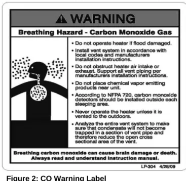
For each floor containing bedroom(s), a carbon monoxide detector and alarm shall be placed in the living area outside the bedrooms, as well as in the room that houses the heater. Detectors and alarms shall comply with NFPA 720 (latest edition). Failure to comply with requirements for detectors and alarms could result in property damage, severe personal injury, or death.
E. EXHAUST VENT AND INTAKE PIPE SIZING
1. The exhaust vent and intake pipe size is 2" (5 cm) for the PH100 and PH130 and 3" (7.6 cm) for the PH160 and PH199.
2. The maximum total equivalent length of 2” (5 cm) exhaust vent and intake pipe must not exceed 85 feet (26 m). The total maximum equivalent length of 3” (7.6 cm) exhaust vent and intake pipe must not exceed 200 feet (61 m).
a. The equivalent length of elbows, tees, and other fittings are listed in the Friction Loss Table, Table 5: FRICTION LOSS EQUIVALENT IN PIPING AND FITTINGS
FITTINGS OR PIPING EQUIVALENT FEET
2” (5 cm) 3” (7.6 cm) 4” (10 cm)
90 DEGREE ELBOW* 5’ (1.5 m) 5’ (1.5 m) 3’ (91 cm)
45 DEGREE ELBOW 3’ (91 cm) 3’ (91 cm) 1’ (30 cm)
COUPLING 0’ 0’ 0’
AIR INLET TEE 0’ 0’ 0’
STRAIGHT PIPE 1’ (30 cm) 1’ (30 cm) 1’ (30 cm)
CONCENTRIC VENT KIT 3’ (91 cm) 3’ (91 cm) N/A
V500 2” (5 cm) VENT KIT 1’ (30 cm) N/A N/A
V1000 3” (7.6 cm) VENT KIT N/A 1’ (30 cm) 1’ (30 cm)
V2000 4” (10 cm) VENT KIT N/A 1’ (30 cm) 1’ (30 cm)
Table 5 - *Friction loss for long radius elbow is one (1) foot (30 cm) less.
NOTE: Consult Polypropylene venting instructions for friction loss and pressure drop equivalents.b. For example: If the exhaust vent has two (2) 90° elbows and ten (10) feet (3 m) of PVC pipe we will calculate: Exhaust Vent Equivalent Length = (2x5) + 10 = 20 feet (6 m).
Further, if the intake pipe has two (2) 90° elbows, one (1) 45° elbow and ten (10) feet (3 m) of PVC pipe, the following calculation applies:
Intake Pipe Equivalent Length = (2x5) + 3 + 10 = 23 feet (7 m). Finally, if a concentric vent kit is used we find:
Total Equivalent Length = 20 + 23 + 3 = 46 feet (14 m).
The total equivalent length is 46 feet (14 m) which is well below the maximum of 85 feet (26 m). 3. The minimum total equivalent length is 16 equivalent feet (5 m).
Failure to provide a minimum total vent length of 16 equivalent feet (5 m) could result in property damage and improper product operation.
F. LONGER VENT RUNS
The maximum total equivalent length can be extended by increasing the diameter of both exhaust vent and intake pipe equally. However, the transitions should begin a minimum of 15 total equivalent feet (4.6 m) from the water heater.
a. The maximum total equivalent length for increased diameter vent pipes is 125 feet (38 m) for 2” (5 cm) transitioning to 3” (7.6 cm) pipe (this number includes the minimum 15 total equivalent feet (4.6 m) necessary for transition), and 200 maximum total equivalent feet (61 m) for 3” (7.6 cm) transitioning to 4” (10 cm) pipe (including the minimum 15 total equivalent feet (4.6 m) necessary for transition).
b. Transitions should always be made in vertical sections of pipe to prevent the condensate from pooling in the vent pipe. MODEL MAXIMUM TOTAL EQUIVALENT LENGTH AT
STANDARD VENT CONNECTION
REDUCING COUPLING
MAXIMUM TOTAL EQUIVALENT LENGTH AT MAXIMUM INCREASED VENT SIZE PH100 PH130 85’ (26 m) @ 2” (5 cm) 3” (7.6 cm) X 2” (5 cm) 125’ (38 m) at 3” (7.6 cm) PH160 PH199 200’ (61 m) @ 3” (7.6 cm) 4” (10 cm) X 3” (7.6 cm) 200’ (61 m) at 4” (10 cm)
Table 6: Vent Sizing – Diameter and Length
c. If the transition occurs at a distance greater than 15 equivalent feet (4.6 m) from the water appliance, the maximum equivalent length will be reduced.
Total maximum equivalent length of increased diameter exhaust vent and intake pipe must not exceed the lengths defined in this manual. 125 maximum total equivalent feet (38 m) for 2” (5 cm) increased to 3” (7.6 cm) diameter vent pipe; 200 maximum total equivalent feet (61 m) for 3” (7.6 cm) increased to 4” (10 cm) diameter vent pipe. Failure to keep the total equivalent length below the maximum lengths determined in this manual will result in faulty appliance operation, substantial property damage, serious personal injury, or death.
TRANSITION POINT (FT. FROM
WATER APPLIANCE) TEL OF OVERSIZED VENT PIPE (FT.)* MAXIMUM TEL OF ALL VENT PIPE (FT.)
15 (4.6 m) 95 (29.0 m) 125 (38.0 m) 20 (6.0 m) 77.5 (23.6 m) 117.5 (35.8 m) 25 (7.6 m) 60.5 (18.4 m) 110.5 (33.7 m) 30 (9.1 m) 43 (13.1 m) 103 (31.4 m) 35 (10.7 m) 26 (7.9 m) 96 (29.3 m) 40 (12.2 m) 8.5 (2.6 m) 88.5 (27.0 m) NONE 0 85 (26.0 m)
Table 7 – TEL = Total Equivalent Length *Oversized vent pipe diameter is 1” (2.5 cm) or greater than factory
supplied connection.
G. EXHAUST VENT AND INTAKE PIPE INSTALLATION
All joints of positive pressure vent systems must be sealed completely to prevent leakage of flue products into living space. 1. Use only solid PVC or CPVC pipe or a Polypropylene vent system approved for use with Category IV appliances.
FOAM CORE PIPING IS NOT APPROVED FOR EXHAUST VENT APPLICATIONS. Foam core piping may be used on air inlet piping only.
2. Remove all burrs and debris from joints and fittings.
3. When using PVC or CPVC pipe, all joints must be properly cleaned, primed, and cemented. Use only cement and primer approved for use with the pipe material. Cement must conform to ASTM D2564 for PVC and ASTM F493 for CPVC pipe. NOTE: DO NOT CEMENT POLYPROPYLENE PIPE.
4. Ensure the vent is located where it will not be exposed to prevailing winds.
5. In all roof venting applications, exhaust discharge must point away from the pitch of the roof. 6. To prevent water leakage, install adequate roof flashing where the pipe enters the roof.
7. Do not locate vent over public walkways, driveways, or parking lots. Condensate could drip and freeze, resulting in a slip hazard or damage to vehicles and machinery.
8. Due to potential moisture build-up, sidewall venting may not be the preferred venting option. To save time and cost, carefully consider venting installation and location.
9. Horizontal lengths of exhaust vent must slope back towards the water heater not less than ¼" (6.3 mm) per foot to allow condensate to drain from the vent pipe.
10. The exhaust vent must terminate where vapors cannot make accidental contact with people or pets, or damage shrubs or plants. 11. In vacant chimney applications, install and seal a rain cap over existing chimney openings.
12. All piping must be fully supported. Use pipe hangers at a minimum of four (4) foot (1.2 m) intervals to prevent sagging of the pipe where condensate may form.
13. Do not use the heater to support any piping.
14. A screened straight coupling is provided with the heater for use as an outside exhaust termination. 15. A screened inlet air tee is provided with the heater to be used as an outside intake termination. Table 8 lists optional intake air/exhaust vent terminations available from GIANT:
DESCRIPTION STOCK CODE
2” (5 cm) PVC CONCENTRIC VENT TERMINATION KIT KGAVT0501CVT 3” (7.6 cm) PVC CONCENTRIC VENT TERMINATION KIT KGAVT0601CVT
2” (5 cm) STAINLESS STEEL VENT TERMINATION KIT V500 3” (7.6 cm) STAINLESS STEEL VENT TERMINATION KIT V1000
4” (10 cm) STAINLESS STEEL VENT TERMINATION KIT V2000
3” (7.6 cm) POLYPRO VENT KIT 8400P-001
Table 8
H. VENTING DRAWINGS
1. DIRECT VENT INSTALLATION OF EXHAUST VENT AND INTAKE PIPE
If installing a direct vent option, combustion air must be drawn from the outdoors directly into the water heater intake, and exhaust must terminate outside. There are three (3) basic direct vent options detailed in this manual:
1. Side Wall Venting 2. Roof Venting 3. Unbalanced Venting
Be sure to locate the heater such that the exhaust vent and intake piping can be routed through the building and properly terminated. Different vent terminals can be used to simplify and eliminate multiple penetrations in the building structure (refer to the Venting Section). The exhaust vent and intake piping lengths, routing and termination methods must all comply with the methods and limits given in the Venting section, Part 5 of this manual.
When installing a combustion air intake from outdoors, care must be taken to utilize uncontaminated combustion air. NOTE: To prevent combustion air contamination, see Table 1: Contaminant Table.
Take extra precaution to adequately support the weight of vent pipes terminating through the roof. Failure to properly support roof terminated vent piping could result in property damage, serious personal injury, or death due to flue gas leakage.
Figure 11: Sidewall Venting -
NOTE: This drawing is meant to demonstrate system venting only. The installer isresponsible for all equipment and detailing required by local codes.
LP
Figure 12: Concentric Venting -
NOTE: This drawing is meant to demonstrate system venting only. The installer is responsible for all equipment and detailing required by local codes.LP
Figure 13: LP-179-F -
NOTE: This drawing is meant to demonstrate system venting only. The installer is responsible for all equipment and detailing required by local codes.Figure 14: Horizontal Venting -
NOTE: Drawing is meant to demonstrate system venting ONLY.NOTES:
A. For every 1” (2.5 cm) of overhang, the exhaust vent must be located 1” (2.5 cm) vertical below overhang (overhang means top of building structure and not two adjacent walls [corner of building]).
B. Typical installations require 12” (30 cm) minimum separation between bottom of exhaust outlet and top of air intake. C. Maintain 12” (30 cm) minimum clearance above highest anticipated snow level or grade (whichever is greater). D. Minimum 12” (30 cm) between vents when installing multiple vents.
E. 12” (30 cm) minimum beyond air intake.
All vent pipes must be glued, properly supported, and the exhaust must be pitched a minimum of ¼” (6.3 mm) per foot back to the heater to allow drainage of condensate. When placing support brackets on vent piping, the first bracket must be within one (1) foot (30 cm) of the water heater and the balance at four (4) foot (1.2 m) intervals on the vent pipe. Heater venting must be readily accessible for visual inspection for the first three (3) feet (91 cm) from the heater.
2. VENTING THROUGH AN EXISTING SYSTEM
This heater may be vented through an existing unused vent system. The inner diameter of the existing vent system is utilized for the combustion air source. Two methods have been approved for such venting: Concentric Venting Through an Existing System and Venting as a Chase.
Do not install the heater into a common existing vent with any other appliance. This will cause flue gas spillage or heater malfunction, resulting in substantial property damage, severe personal injury, or death.