Peer-to-Peer File Sharing Across
Private Networks Using Proxy Servers
by
Shruti Dube
DEPARTMENT OF COMPUTER SCIENCE AND ENGINEERING
INDIAN INSTITUTE OF TECHNOLOGY, KANPUR
Peer-to-Peer File Sharing Across
Private Networks Using Proxy Servers
A Thesis Submitted
in Partial Fulfillment of the Requirements for the Degree of
Master of Technology
by
Shruti Dube
(Y3167337)
to the
DEPARTMENT OF COMPUTER SCIENCE AND ENGINEERING
INDIAN INSTITUTE OF TECHNOLOGY KANPUR
Acknowledgment
The area of Computer Networks had me fascinated ever since its first introduction to us in our fifth semester, leaving me with a wish to learn more about this field and thus inspiring me to do several courses and projects in the same. I would like to express my sincere gratitude to Dr. Dheeraj Sanghi for initiating and furthering my interest in the subject through his instruction in the three courses which I have credited under his guidance. I am also extremely grateful for the advice, innovative suggestions, supervi-sion I have received from him as my thesis guide at every stage of problem formulation, background research, system design and implementation. Advice such as, appreciating the all-encompassing view of every technology or project and not getting weighed down by a biased positive perspective shall stay with me for long times to come. For all such insights, I would like to whole heartedly thank Sir.
I look upto my parents in admiration for all the efforts they have put in for my edu-cation. I wish to express my deep indebtedness to them for their support throughout my academics and extra curricular activities. I am also very thankful to my brother for his constant belief which urges me on in the wake of difficulties.
To this institute, my home for the past five years which has helped me gain knowledge, think inquisitively and given me immense opportunities to grow and mature as a better person, no words can express my gratitude. I hope I shall prove worthy of and true to the teachings of my parents, teachers, school and institute.
Abstract
The Internet today is commonly used as a medium to share large size multimedia content. This sharing is carried out, a number of times, through the Peer to Peer sharing architecture rather than the conventional server-client model. The paucity of network addresses in the Internet has led to the emergence of private and global networks. Because the identity of peers in a private network remains hidden behind their global endpoint, P2P applications cannot run between two peers in separate private networks. Techniques such as hole-punching require the use of a centralized entity which serves as a bottleneck to the P2P application.
We have proposed a hierarchical P2P network of private and global networks. Here, the lower tier is formed by the peers in each private network, while the upper tier is formed by the global endpoints (called proxies) of each of these private networks. We have designed a new file sharing protocol, FTPNP, between these proxies which preserves the identities of the actual endpoints of the file transfer, present in separate private networks. We have also created a Credit Management System in order to ensure fairness and incentive to share in the designed hierarchical P2P system. We have implemented all the above proposed features and tested them to ensure the preservation of the essential features of a P2P network.
Contents
1 Introduction 1
1.1 Peer to Peer Content Distribution Networks (P2P CDN) . . . 1
1.2 Characteristic features of P2P CDNs . . . 3
1.3 BitTorrent: P2P file sharing protocol . . . 4
1.4 Private and Global Networks . . . 6
1.5 An Overview of the Thesis . . . 8
1.6 Organization of the Thesis . . . 8
2 Literature Survey 10 2.1 Hierarchical Networks . . . 10
2.1.1 Unstructured P2P Networks . . . 11
2.1.2 Structured P2P Networks . . . 13
2.2 Hole Punching: Overcoming NATs . . . 14
2.3 Motivation . . . 16
3 Proposed Model: Usage of Proxies 18 3.1 Challenges . . . 18
3.2 System Model Assumptions and Configuration . . . 19
3.3 System Design and Architecture . . . 20
3.3.1 Private P2P network . . . 20
3.3.1.1 BitTorrent Clients . . . 20
3.3.1.2 BitTorrent Tracker . . . 21
3.4.1 Peers . . . 23
3.4.2 FTPNP - File Transfer Protocol for Network of Proxies . . . 23
3.4.2.1 Packet Architecture of FTPNP . . . 25
3.4.2.2 Communication Protocol Specification . . . 26
3.5 Credit Management System . . . 32
3.5.1 Design Issues . . . 32
3.5.2 Components of the Credit Management System . . . 34
3.6 Working of the Hierarchical P2P Network . . . 36
3.6.1 File Sharing . . . 36
3.6.2 File Download . . . 38
3.6.2.1 Requested file is in the same private network . . . 38
3.6.2.2 Requested file is in another private network . . . 38
3.7 Components of the proxy . . . 42
3.8 Features of the Hierarchical P2P Network . . . 44
4 Implementation and Results 46 4.1 Private P2P Network . . . 46
4.2 Global P2P Network of Proxies . . . 47
4.3 File Transfer across two Private Networks . . . 48
4.3.1 Setup Topology . . . 48
4.3.2 Test Details . . . 48
4.4 Credit Management System . . . 49
4.4.1 Test Details . . . 49
4.4.2 Results and Inferences . . . 50
4.4.2.1 Single Peer Case . . . 50
4.4.2.2 Two Peer Case . . . 51
List of Figures
1.1 Server-client architecture and Content Distribution Network . . . 2
1.2 The Peer to Peer (P2P) architecture . . . 3
1.3 Working of the BitTorrent protocol . . . 6
1.4 The global and private IP address domains . . . 7
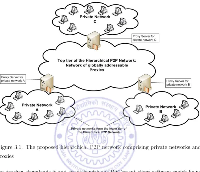
3.1 The proposed hierarchical P2P network comprising private networks and proxies . . . 21
3.2 High level overview of the steps in the FTPNP . . . 24
3.3 Fields in a FTPNP packet . . . 25
3.4 Sequence of control and data messages in FTPNP . . . 27
3.5 Algorithm to share a file . . . 37
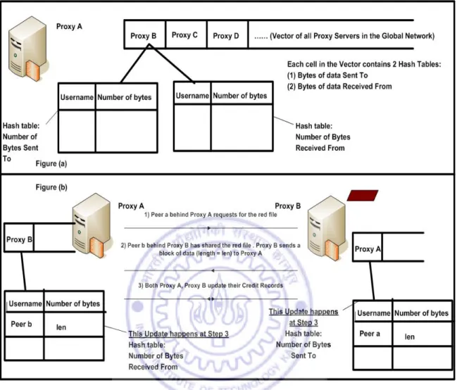
3.6 (a)The structure of the Credit Records at each Proxy. (b)The updation of credit records when file transfer occurs between two proxies . . . 41
3.7 Downloading a file not present in the same private network . . . 42
3.8 Components of the proxy . . . 43
4.1 Experimental testbed . . . 48
4.2 Download time for the desired file vs. size of content shared . . . 51
4.3 Download time for the desired file vs. size of content shared . . . 52
4.4 Dependence of the time to download a file on the size of the content shared . . . 54
4.5 Dependence of the time to download a file on the size of the content shared . . . 55
4.6 Dependence of the time to download a file on the size of the content shared . . . 56 4.7 Dependence of the time to download a file on the size of the content
shared . . . 57 4.8 Dependence of the time to download a file on the size of the content
shared . . . 58 4.9 Dependence of the time to download a file on the size of the content
Chapter 1
Introduction
1.1
Peer to Peer Content Distribution Networks
(P2P CDN)
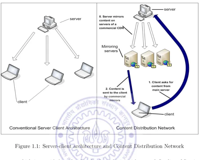
The Internet can be looked upon as a medium to disseminate information. Distribution of large size multimedia content has become commonplace today. The original stereo-type of content distribution was the server-client architecture, wherein a dedicated server furnished the required content to all requesting clients. However such a system faces a bottleneck from the constraints of available upload bandwidth and resources at the server and is thus incapable of scaling up to serve a large number of clients. This problem of sharing content with a large number of clients was solved through two main techniques. One was through the use of large-scale commercial content distribu-tion services (see figure 1.1), example Akamai [1], which mirror customers’ content to be published on various servers and employ sophisticated algorithms to locate the mirroring server from which content is transferred to the requesting client. The second method, peer to peer content distribution, entails the formation of a network topology in which there is no defined server-client architecture and each node (or peer) in the topology has the capability of acting as the source, transferring agent or requester of content.
Figure 1.1: Server-client architecture and Content Distribution Network
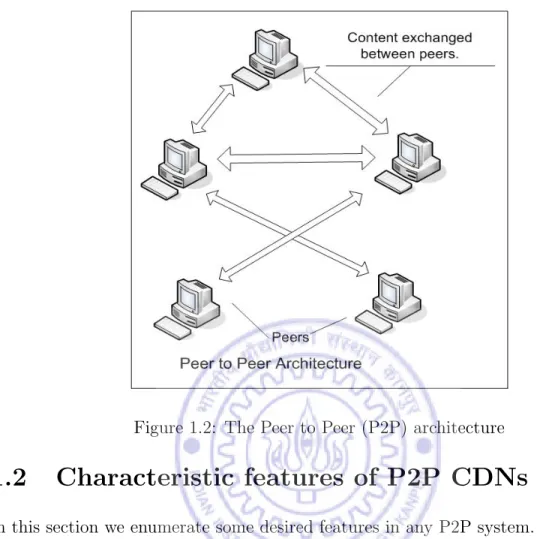
content which is provided to the downloading clients with several Quality-of-Service features. Downloading clients are thus often charged for the content they have down-loaded. The fundamental premise of P2P networks (see Figure 1.2) is the concept of sharing of content and resources amongst all participants of the network. Hence, as the number of peers increases, the resources available to the system increase too and thus such a system is fundamentally scalable. Though some variations exist, P2P networks are characterized by the absence of a central server and the peers are capable of joining or leaving the network at any time without any centralized control. The P2P CDNs are consequently self-organizing, dynamic and scalable networks. In our work, we shall focus on such P2P CDNs.
Figure 1.2: The Peer to Peer (P2P) architecture
1.2
Characteristic features of P2P CDNs
In this section we enumerate some desired features in any P2P system.
• Authenticity and privacy: It must be ascertained that unauthorized peers are not able to make changes to the content shared or substitute forged content in place of the correct content to be shared. The system must have mechanisms in place to ensure that only authorized peers are entitled to access available content. Several systems impose restrictions on the type of content being shared.
• system stability: The topology of a P2P system changes continuously as peers join and leave. The system should remain stable and continue to provide services at all times. Though the topology of the system is subject to change, the peers which are a part of the system at any given time should remain unperturbed by the dynamics and their functioning should continue as normal.
the final receipt of the desired content. Similarly, the time to complete other requests like searching, uploading, browsing for content on the system are also taken into account.
• scalability: The system’s performance is not expected to degrade even in the wake of an increase in the number of peers or the volume of the content shared. The increased number of peers in the network should imply an increase in the number of resources available to the system.
• fairness: The performance of the system as experienced by a peer should be contingent with the utility of the peer to the system. Neither should a peer get any undeserved advantage (e.g. disproportionately large share of the bandwidth) nor should a peer be unfairly penalized (due to scarcity of resources or hogging of the bandwidth by another peer). The system should be able to identify “free-riders” who scarcely contribute their resources to the network, but utilize the resources shared by other peers.
• incentive to share: Sharing is the fundamental requirement of a P2P network. The performance of such a network bears heavily on the willingness of the par-ticipating peers to share content and resources. Thus to ensure the successful working of a P2P networks, there should be a natural incentive to share. Better quality of service features to peers who prove their utility (peers who share more content and contribute more resources) to other peers, are common incentives given to peers in a P2P network.
1.3
BitTorrent: P2P file sharing protocol
In this section, we will review basic concepts of the BitTorrent protocol[2], a widely-used P2P content sharing protocol. The content to be shared is broken into blocks of a fixed size and these chunks of data are then downloaded from different peers which have the desired file. These chunks are assembled in their correct order by the requesting
peer. The requested file thus reaches the peer who had initiated the request for the same. The main elements of BitTorrent are:
• Torrents: For every file that is to be shared using BitTorrent, a corresponding torrent file is required to be made. Also referred to as torrent files, torrents are very small sized files which contain hashed information about the file’s content, and name, length of the file to be shared, number of blocks of data and the size of each block in which the file’s contents are to broken and shared. These files also contain the URL of the tracker (see below).
• Tracker: Every BitTorrent network has a unique machine called the tracker. It is the centralized entity which keeps a record of the peers sharing a partic-ular content and is responsible for coordinating the download of a desired file from several peers which are sharing that content. There are several web-based tracker software available, e.g. Torrent Bits [5] which can be run at the tracker. The tracker software allows peers to register with the tracker, login into their account, browse for shared content, download content and upload torrent files. Some tracker software provide additional functionalities like RSS feeds, discussion forums, personal message boards.
• BitTorrent Client: This is a software which runs at each peer in the P2P system and it helps share and download content from other peers. Bitspirit, U-torrent are some popular BitTorrent client software.
• Uploading content: When a peer wishes to share content with other peers, it creates a torrent file [3] containing the URL of the unique tracker in the system. It then uploads this torrent file on the tracker and shares this file for the P2P network using its BitTorrent client software. This sharing is called seeding of content. Once a file is seeded, it becomes available to other peers for download.
• Downloading content: When a peer wishes to download content from the P2P network, it searches for it on the tracker. If the search is successful, the peer downloads the torrent file for the same. This torrent file is then opened with the
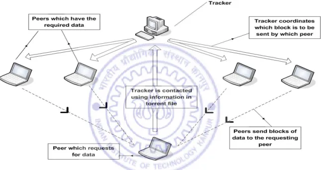
BitTorrent client software. Since the torrent file contains the URL of the tracker, the BitTorrent client software contacts the tracker using this URL. The tracker has a list of peers who are sharing the requested content. Since the requested content is broken into blocks of fixed size for sharing, different peers send different blocks of data to the requesting peer. The tracker coordinates and decides the blocks to be obtained from different peers. These blocks when assembled by the BitTorrent client complete the file download.
Figure 1.3: Working of the BitTorrent protocol
BitTorrent (see Figure 1.3) thus does not adhere strictly to the requirements of a true P2P system and has the feature of centralized control to a certain extent. However the centralized control is only a coordinating agent; the content is shared not from a single server, but from the interaction and exchange of data blocks between several peers.
1.4
Private and Global Networks
In the initial architecture of the Internet, each machine had its own globally routable, unique IP address. But the address space in the Internet is limited and it is no longer
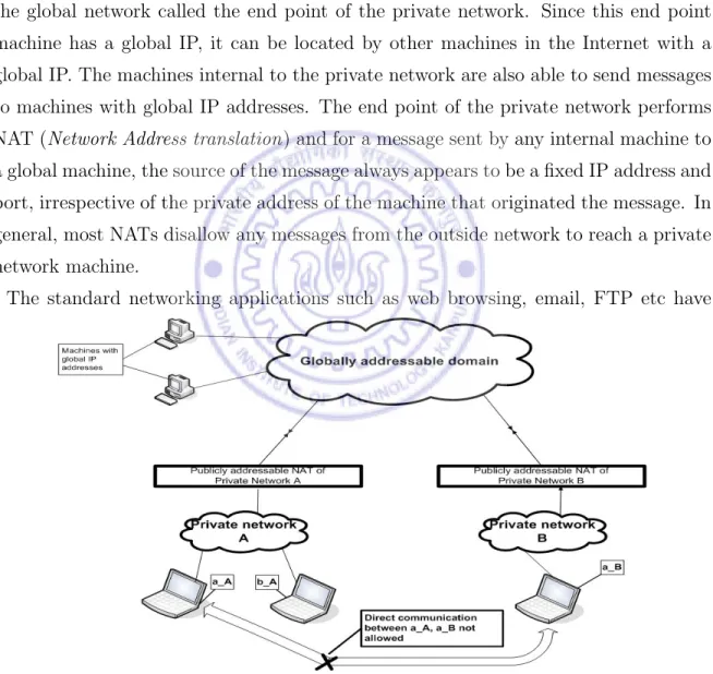
possible to assign each machine in the network with a global IP address. In order to combat this paucity of available addresses, private networks emerged (see Figure 1.4). In a private network, all machines have a local IP address. Since the IP addresses of such machines are local to the private network and they do not have a globally known address, each machine is capable of receiving messages from machines internal to the private network alone. Private networks have a publicly addressable entry point into the global network called the end point of the private network. Since this end point machine has a global IP, it can be located by other machines in the Internet with a global IP. The machines internal to the private network are also able to send messages to machines with global IP addresses. The end point of the private network performs NAT (Network Address translation) and for a message sent by any internal machine to a global machine, the source of the message always appears to be a fixed IP address and port, irrespective of the private address of the machine that originated the message. In general, most NATs disallow any messages from the outside network to reach a private network machine.
The standard networking applications such as web browsing, email, FTP etc have
Figure 1.4: The global and private IP address domains
to peer applications cannot ordinarily run across two such private networks. Even if the two peers are made to communicate by making some changes at the entry point of each private network, a P2P connection can still not be established across the two peers. This happens because due to address translation at the end point of the private networks, the identity of each individual peer is lost. Any machine in a particular private network always appears to be associated with the same IP global address and port number. Thus the uniqueness of the end-points of the P2P connection is lost and P2P applications cannot be run across a system of two private networks.
1.5
An Overview of the Thesis
In our work, we provide a novel solution, using “proxies”, which allows P2P applications to run across different private networks. Peers internal to a private network, which hitherto appeared associated with a common identity to any external machine in the global network, now have a unique identification even outside their private network. Due to this new capability, Quality of Service features, which will depend on the past performance of the individual peer alone and not the collective performance of all peers in an internal network (as used to happen traditionally), were introduced. The proposed scheme creates a hierarchical P2P network which has the essential properties of fairness, incentive to share and scalability. Further, we have implemented our scheme on a test network and we have examined the effectiveness of the Quality of Service features of this system through experiments.
1.6
Organization of the Thesis
The organization of the thesis is as follows: In Chapter 2, we describe different P2P networks, including hierarchical networks, which have been proposed in the past, the approach and problems associated with the process of “Hole Punching” as a means of communicating across peers in different private networks and the motivation for our work. In Chapter 3, we discuss the proposed model of using proxies in building a
hier-archical network comprising the two tier architecture of private and global networks. It also lays out implementation details of the model and explains the working of the incentive mechanism in this proposed system. Chapter 4 elucidates the test bed con-figuration details, the sample runs done on the system and an analysis of the results obtained. Finally in Chapter 5 we present our conclusions and provide directions for future work.
Chapter 2
Literature Survey
2.1
Hierarchical Networks
In this section we will review different types of peer to peer systems and the major issues of research in each architecture.
P2P networks can broadly be classified as unstructured and structured P2P networks. In the former, there is random placement of data on peers. Such networks grow or-ganically as peers join in and there is no fixed or decided overlay which is adhered to. In the latter, there is a fixed structure and overlay network in which data place-ment occurs according to targeted hashing mechanisms. Since P2P systems result in aggregation of resources from several unconnected machines, this accumulation paves the way for formation of a formidable repository of resources which can be utilized for specialized purposes. For example, the idle CPU power of each peer, in a medium-sized P2P network, if utilized well, can result in the development of a system with sophisticated computational capabilities. Since the peers in the network are not aware of the complete topology of the network that they are a part of, locating peers with the desired content efficiently becomes difficult. The method used traditionally is that of message flooding or the aid from a centralized lookup server [7], [8], [9]. Thus a common research area in all P2P systems is the issue of scalability. We shall explore different existing P2P architectures both in the structured and unstructured domain
and describe the extensions made to these networks in order to make them scalable.
2.1.1
Unstructured P2P Networks
On the basis of the mechanism used to locate the peer from which desired data can be downloaded efficiently and the method used to then download the same, we can divide unstructured P2P networks with a flat architecture into the following broad
categories:-• Napster: Napster [10] is a P2P network which was built in order to share music pieces among different peers in the network. There is a centralized indexing server which keeps a record of the content uploaded and the location of the peers which have downloaded the content. Whenever a peer wishes to download content, it contacts the central server, obtains the list of peers which have a copy of the content, ascertains the peer closest to itself and downloads data from it. Since Napster’s working depends critically on the centralized server, scalability is a serious problem for it.
• Gnutella: Gnutella [9] differs from Napster in the fact that there is no centralized indexing server in the former. The peers broadcast query messages to their neighboring peers to find if they have a copy of the desired content. In order to prevent flooding of the network with query messages, a scoped broadcast of these messages is done. A time to live (TTL) value is attached with them and hence only neighboring peers which are atmost a few hops away receive these queries. If the recipient of such a query has the desired content, it returns a reply to the requesting peer, using the reverse path of the incoming message query. Once a peer with the desired content has been located, a direct transfer of the content takes place between the two peers. Though it appears that scalability should not be a problem for such a network with distributed control and limited flooding, [11], [12], [13] show that Gnutella does not scale well due to broadcast queries.
• Freenet: In this P2P network there is no centralized control and the peers locate data based on content-routing. All the content stored in the Freenet [14] is
associated with a unique key field, which is the hash of the content. Each node in the Freenet network maintains a content routing table, which contains a mapping from the file keys to the peers in the network, where the file is assumed to be present. In addition to this content routing table, each peer also has a local data store where data which it wishes to share is stored. When fresh content enters Freenet, the uniqueness of the file key is ascertained and then the content is stored at all the peers which were in the path of the initial query to insert new data into the network. In order to search for a file, a peer searches for its file key in its content-routing table. A request to find the file is then sent to the peer associated with the closest lexicographic entry to the searched file key. This is a cumbersome and time-consuming process and this depth-first search technique of Freenet is not ideal for scalability purposes.
To combat these scalability issues, a hierarchical network has been proposed [15], which combined some of the techniques from the three architectures mentioned above for fast content location and content transfer. This network uses content hierarchy for routing of request and reply messages. This method of locating a peer with the desired content is better than the request broadcast mechanism which results in flooding. All content is associated with a content vector and a comparison of two content vectors yields information about how similar or different the associated contents are. Utilizing the distances between these content vectors, content clustering trees can be formed. For each such content cluster, a content search tree is developed. Hierarchical content routing is then done based on the location of these content search trees in the P2P network. When the query is routed to the root of the content search tree, further routing decisions are based on the routing scheme of the particular content search tree. Once the desired content is found at a node, a reply is sent back to the root of the content search tree and then back to the node that had initiated the search. As a fallout of this technique, adaptive schemes for content placement at the nodes of the system were developed. These schemes allow the replication of popularly accessed content nodes in different clusters, migration of content nodes to a region which is the most frequent requester of that content and the development of shortcut links between
content nodes and the nodes creating heavy traffic on those content nodes. The focus of research is thus on:
1. ensuring scalability to thousands and millions of nodes 2. content allocation reflecting load usage and locality
3. appropriate cluster formation with similar content vectors getting grouped to-gether, and
4. efficient routing capabilities based on hierarchical, content-dependent routing.
2.1.2
Structured P2P Networks
In structured P2P networks, the topological properties of the overlay network and the addressing mechanism help to build the system in which exchange of content can take place via different protocols. Several such networks have been proposed in the past, such as Chord [16], Pastry [19], CAN [18] etc. The emphasis of the research is on making the lookup services efficient. All these protocols make use of theDistributed Hash Tables
(DHTs) for the semantic-free, content-driven routing. Each peer is associated with a peerID (usually the hash of the IP address) and each data content is associated with a KeyID (usually the hash of the content). Each peer stores information about peers in the network which have KeyIDs close to the KeyID of the content they possess. A likelihood function determines the structure of the P2P overlay network. This function is used by the routing algorithm to acquire information stored at different nodes about adjacent peers. In order to locate desired content, the requesting peer looks up the node whose keyID is closest to the required content, thus propagating the request till the desired content is finally found. This structured method of answering queries is an efficient way of locating content.
In order to introduce the feature of scalability into these structured P2P networks with flat DHT designs, hierarchical networks with a two-tier architecture using DHTs were proposed [20]. In this system, peers are organized into several groups which have their own autonomous intra-group overlay network and lookup service. These groups form
an overlay network as well. Thus a two-level hierarchy is formed between the peers. In order to search for a desired content, the search is broken down into two levels, first task involved is ascertaining the group to which the desired keyID belongs and then using the routing mechanism of the ascertained group, the desired content is found. The authors in [20] have implemented the proposed hierarchical network for a two tier architecture, wherein the top-level uses Chord [16] as the overlay network. They have proved that the use of hierarchical networks reduces the expected number of hops as compared to a flat-design of Chord.
Some other hierarchical networks have been proposed in order to address the scalability issue. The authors in [21] propose a hybrid hierarchical P2P network which combines DHT and flooding in an aim to increase scalability, efficiency and stability.
The focus of research in structured hierarchical network is on:
1. discovering information about the topology of the overlay network, 2. using distributed hash tables for efficient content driven routing,
3. combining search techniques with DHT (e.g., content driven routing or flooding) for building faster look-up service, and
4. ensuring system stability along with reduced time for routing in comparison to the time for the same in a flat network.
2.2
Hole Punching: Overcoming NATs
The limited size of the address space in the Internet and the need to enforce security measures restricting access to machines internal to a network resulted in the develop-ment of private and global networks. The Internet can now be visualized as a number of private networks interconnected together on the global network through their re-spective Network Address Translators (NATs). These NATs, allow machines internal to a network to send messages to the known globally addressable machines (by assign-ing a common global IP, common port for all outgoassign-ing connections from their private
network). But they usually restrict any incoming traffic from external machines to the private network. Given this, if one wishes to communicate across two private networks, it does not seem possible. However, in [22] the authors have detailed hole punching as a technique for NAT traversal which shall allow machines in separate private networks to communicate with each other. Thus P2P applications can run in a global network of private networks using this support. There are several ways in which hole punching can be implemented. The common feature of all these methods is that they require support from an external server to which all peers in both the private networks can establish connections.
• Relaying: Consider two machines A and B in separate private networks and an external server S, whose global IP address is known to both A and B. They send outgoing messages to S. Thus the NAT in their respective private network knows about the existence of an external server S. Now when S sends a reply to the A and B, the NATs in their respective private networks allow the messages to be sent to A and B. Thus both these machines are able to establish connections with the external server S. In order to send messages from A to B, a direct connection is not permitted by the NATs of their respective private networks. A sends a message to S and S then relays this message to B. B follows a similar process for communicating with A. This method though reliable and robust, is most inefficient, since all messages between any two peers are required to go through a fixed server. This makes the external server a bottleneck and the system is thus inefficient.
• Using a Rendezvous Server: In order to eliminate the problems in the previous method, rendezvous servers (R) were employed to implement hole punching. The machines A and B are assumed to have already established sessions with the ren-dezvous server R. When a machine in the private network contacts the renren-dezvous server, R registers the machines public endpoint (IP address and the port from which R observes the packet to be coming from) and the private endpoint (actual internal IP address and port mentioned in the fields in the incoming packet from the peer). A and B separately register with R, which maintains the list of their
public and private endpoints. When A approaches R in order to send a message to B, R sends the private and public endpoints of B to A and also the private and public endpoints of A to B. A and B then send messages to both the private and the public endpoints of the other peer. They then receive a reply from one of the two endpoints of the other peer and thus a connection can now be established using the endpoint of the peer which responded.
Though this allows peers in different private networks to communicate with each other, it can happen only with the aid of an external central server. Thus this design is not scalable and is inefficient if there are a large number of requests generated by the peers for communication with different peers in another private network.
2.3
Motivation
Say, we have some private P2P networks who wish to collaborate the content which peers in each private network are sharing. Each of these private networks has an end-point, which is globally addressable. To the outside world, since the endpoint is the representative of all the peers in the internal network, they are often referred to as
Proxies. For example, say, all the IITs, which have their own internal private P2P networks, decide to allow content distribution and sharing of files across their private networks. In such a prospective network, the proxies in each private network will be aware of the addresses of other globally accessible proxies in such an arrangement. Peers internal to a private network would share content among them and would con-tact peers of other networks only if search in their own private network did not result in locating the required content. Thus this would be a hierarchical network wherein, the peers internal to the private P2P networks form the lower tier of the hierarchy and the top level would be a P2P network between the proxies of the respective private networks.
Till now in hierarchical P2P networks which have been proposed, the focus has been on ensuring scalability, placement of data at nodes, defining an efficient overlay network structure and routing mechanisms. However, such P2P networks cannot be used to
solve the problem in the scenario above where the focus is on ensuring communica-tion between members present in two different private networks (which was hitherto assumed possible in the hierarchical networks which have been proposed) and not on defining the network overlay (which has already been defined), routing algorithms, con-tent placement (which is also predefined) and scalability. In order to solve the problem of communication between peers in separate private networks, using hole-punching may seem like a possible solution. However, in doing so, there would be a centralized entity through which all the messages would have to pass through. Control messages, because of their small size, may still be handled, however such a network cannot sustain the transfer of large media files between two private networks. Thus we were motivated to build a hierarchical P2P network which could help us solve this problem and allow files to be transferred between peers located in different private networks.
There is another application where our proposed system will find application, namely, content distribution for mobile phones. With India alone expecting to reach 500 million subscribers by end of 2010, the number of mobile phones is on an unprecedented rise. These mobile phones now come with sophisticated functionality, such as GPRS, Java Runtime Environment, video and audio recording and playback etc. Due to the large number of these mobile phones, assigning each handset an individual IP address is an impossible task in the wake of the constraints on the size of the IP address space. In order to resolve this problem, the mobile phones are given private IP addresses and they appear to possess a single global IP address to all mobile phones in other Mobile Service Provider networks. Our model can be used by those mobile phone users who wish to share multimedia content with other mobile phone users. The large storage capacity possessing servers set up by the mobile service providers, act as a proxy for all mobile phones using their service. Thus we can build an analogous P2P content sharing mechanism for mobile phones using proxy servers set up by the mobile service providers.
Chapter 3
Proposed Model: Usage of Proxies
3.1
Challenges
There were several challenges which we faced while designing a solution for this prob-lem. Some of the major design challenges
were:-• We wish to build a generic architecture so that if some private networks come together to form such a hierarchical network, changes have to be made only at the respective proxies of the private networks. The individual peers of the private networks may well be oblivious of the existence of such a collaboration with other private networks. Thus there should be no change required to be made at the individuals members of the private networks.
• Building an automated Proxy (globally addressable endpoint of a private net-work) which shall act both as a peer for the P2P network in the private network and also as a peer in the global network of the proxies. It should thus automatedly decide its actions based on the network from which a message comes.
• The content in either P2P networks should be shared such that it conforms to the P2P protocol followed in that particular network
• Any P2P network must ensure fairness, scalability, privacy, performance and an incentive to share. For most of these to be guaranteed, the identity of the
end-points of the exchange must be known to the peers involved in the transaction. However, in case of private networks, even through hole punching [22], the end-points of a communication remain masked. Thus there is no way to know the real end points of a communication. However, with our system design we shall be able to ascertain the real end points of the communication.
In the following sections, we shall review the features of the proposed system in detail.
3.2
System Model Assumptions and Configuration
We shall first lay out the basic parameters which are assumed in our design and also outline the configuration details of the system. Please note that some of these as-sumptions are not critical to the design and have been mentioned only to describe our work.
The system assumes that the following hold true for the hierarchical network:
• Gigabit LAN speeds are very common in today’s private networks. Since the time to transfer content between two peers on a LAN is usually small on a Gigabit LAN. P2P file sharing protocols like BitTorrent, even when employed on such high speed LANs, have mechanisms in place to ensure that peers who share more content receive a better quality of service in terms of faster downloads.
• Speeds in the upper-tier global P2P network are generally of the order of kilo-bits per second. The time taken to transfer files in the global network is thus the bottleneck for the system’s performance. Peers who share more useful con-tent, downloaded by peers in another private network should get better rates of download in the global network.
• The proxy servers have a large storage space and are capable of holding the content being shared by peers in their private network
• Since the system’s architecture is a result of the conscious collaboration between proxies of different private networks, a list of all the members in the top-tier of this hierarchical network is available with all the proxies.
• In order to implement the system, it was important to choose a P2P network for file sharing which would run in all private networks. Due to its popularity of usage, robustness and ability to scale, BitTorrent [2] was chosen as the P2P network running in each private network. But the design of the proxy provides flexibility to integrate any other file sharing P2P protocol in future. Only a small amount of customization code will need to be written.
3.3
System Design and Architecture
There are several components of the design architecture (see Figure 3.1), the primary ones being, proxy, private network peers, global network of proxies, file sharing in the private network and file sharing across the global network. We shall now look at each component in further detail.
3.3.1
Private P2P network
All private networks in the hierarchical network system run the BitTorrent P2P file-sharing protocol. As we had mentioned above, it is just a choice based on the popularity of BitTorrent and it is possible to integrate other P2P systems as well. We shall now examine how the basic components of the BitTorrent protocol are modified in order to make them suitable for the hierarchical network setup.
3.3.1.1 BitTorrent Clients
One of the requirements of the system is that there will be no change in the working of the peers in the private networks. In a BitTorrent P2P network, each peer runs a BitTorrent client at its machine and registers itself as a member of the BitTorrent network. In order to upload content, the peer creates a torrent for the content to be shared (and the URL of the tracker for the private network). The peer then uploads this torrent onto the tracker and also seeds the content through the BitTorrent client software. In order to download content, the peer searches for the desired torrent file on
Figure 3.1: The proposed hierarchical P2P network comprising private networks and proxies
the tracker, downloads it and opens it with the BitTorrent client software which helps the peer to download the file. All these functions take place normally with the peer being completely oblivious to the existence of other private networks.
3.3.1.2 BitTorrent Tracker
The proxy has a two-fold objective, the first is to act as the tracker for the internal BitTorrent P2P systems and the second is to play the role of a peer in a P2P file sharing network of globally addressable proxies. As a tracker, the proxy runs the BitTorrent tracker software which contains support for users to register themselves as peers for this P2P network, login to their accounts, browse for content shared by other peers in the same network, download torrent files and use them to download desired content and upload torrent files for content they wish to share. The tracker thus is a webserver
which maintains a database of peers registered with it and the torrents uploaded. It also coordinates the download of desired content from different peers sharing the content. These were some of the conventional tracker functions it performs. In addition to this, the following functions also take place in different components of the proxy.
• Data Store: This component stores content which is downloaded by the tracker in the proxy. The size of this storage is large and is capable of storing any content being shared by peers in the private P2P network. This has been done so that the proxy can share internal content with external networks without any significant delay.
• Peer Emulator: By default, each tracker has a dummy user registered with it. This dummy user plays the role of the administrator of the tracker. The tracker in each of the private networks, apart from its specialized functions, also acts as a peer in the private P2P network and it is capable of downloading content directly from other peers in the system using BitTorrent. There is a BitTorrent Client software which runs at the tracker as well. This functionality is used for transferring content from peers in the private P2P network to the tracker alone. The downloaded content is stored in the Data Store
• Advanced Upload Manager: This component of the tracker ensures that when a peer uploads a torrent for sharing content, the torrent becomes visible to other peers browsing for data and it also initiates the Peer Emulator functionality of the tracker. Any torrent uploaded is automatically queued for download in the BitTorrent client software which runs in the Peer Emulator component of the tracker. The tracker coordinates the download of the content shared by the peer to the Peer Emulator at the tracker. Thus the tracker always has the torrent and a copy of the content being shared by a peer in the P2P private network.
• Auto Torrent Executor: This component of the tracker keeps checking peri-odically to find if there are any new torrents in the Data Store which have not been executed as yet by the Peer Emulator. When it locates any such torrent, it
inserts the torrent into the torrent database and the administrator of the tracker is registered as the owner and uploader of this torrent. It then opens the torrent using thePeer Emulator. Thus now the torrent is available for download to peers in the private network.
• Torrent Manipulator: This component of the tracker requires a torrent as an input, reads encoded information such as name of the file being shared, length of the file, hashed information in the torrent and the tracker URL of the torrent. It then decodes this information and manipulates this information read such that the original tracker URL of the torrent is changed to the tracker URL of the tracker running on the proxy. This stream is then encoded back and written back into the torrent file. The torrent (which had a different tracker URL and hence belonged to a different P2P network) now becomes a torrent in the current P2P network whose tracker URL is that of the tracker in the proxy for the particular P2P network. This torrent is then detected by the Auto Torrent Executor and consequently added to the torrent database.
3.4
Global P2P Network of Proxies
We shall now examine the components of the top-tier or the global P2P network.
3.4.1
Peers
The proxy servers of the respective private networks form the peers of the top-tier of the hierarchical P2P network. All these proxy servers have globally reachable IP addresses. Each of these peers runs the customized P2P file transfer protocol for such a network of proxies, FTPNP (described below).
3.4.2
FTPNP - File Transfer Protocol for Network of Proxies
This is the file transfer protocol used in the global P2P network of proxies. In case a peer in a private network is unable to locate the desired content within its private
Figure 3.2: High level overview of the steps in the FTPNP
network, the proxy particular to that network tries to fetch the file from proxy servers of other networks. Though the file transfer in the global P2P system takes place between two proxy servers, we wish to know the real endpoints of this transaction i.e. though the apparent endpoints of the file transfer are the two proxy servers, we wish to make information about the requesting peer (in the first private network) and the content-granting peer (in the other private network) available to both the proxy servers involved in the transaction. No current P2P file transfer protocol allows us the capability of ascertaining the participating peers behind proxy servers in private networks. Thus we developed a new P2P file sharing protocol FTPNP to solve this challenge. Figure
3.2 gives a high level overview of this protocol for file transfer between the globally addressable proxy servers. We shall now examine the details of this protocol
3.4.2.1 Packet Architecture of FTPNP
For communicating between peers, different types of messages are used. Some messages are used to exchange control messages, while the others help to transfer content from one peer to another. All these messages are encapsulated in UDP packets. The FTPNP protocol message is the payload of the UDP packet. We shall examine the fields of FTPNP’s message (see Figure 3.3).
Figure 3.3: Fields in a FTPNP packet
• Type: This field can hold two values,ProtocolandData. The former indicates that the message is an asynchronous signaling control message from one peer to another. The latter indicates that the message is being used to send a block of data from one peer to another.
• Info: If the Type field of the packet is “Protocol”, Information can be “Find”, “Available”, “Send”, “Now Sending” and “Successful Receive”. If the Type field of the message is “Data”, Information can be either “Data” or “Torrent”. We shall look into each one of these fields in detail below.
• Filename: This field is used to communicate between two peers the name of the file which is being searched or exchanged between two peers.
• FP at Sending End: This field contains the position of the file pointer of the file “filename” stored at the node sending the packet.
• FP at Opposite End: This field contains the position of the file pointer of the file “filename” stored at the node which will receive this packet being sent (which is also the node which had sent the previous packet).
• Length: If the Type field of this packet holds the value “Data”, then this field gives the length of the data (in bytes) being sent in this packet. If the type of the packet is “Protocol”, this field is inconsequential.
• Uploading Client: If search for the file “filename” yields a positive response from the proxy of a particular private network, the username of the peer (as registered with the tracker in the proxy) in the private network which was the original uploader of the content is contained in this field.
• Requesting Client: This field contains the username of the peer (as registered with the tracker in the proxy) in the private network, which had initiated the search of the file “filename”.
• Byte Data Array: If the Type field of the message is “Data”, then this field contains the data or content being sent. The content is sent in the form of a byte data array. When properly parsed, this packet yields the data which was sent.
3.4.2.2 Communication Protocol Specification
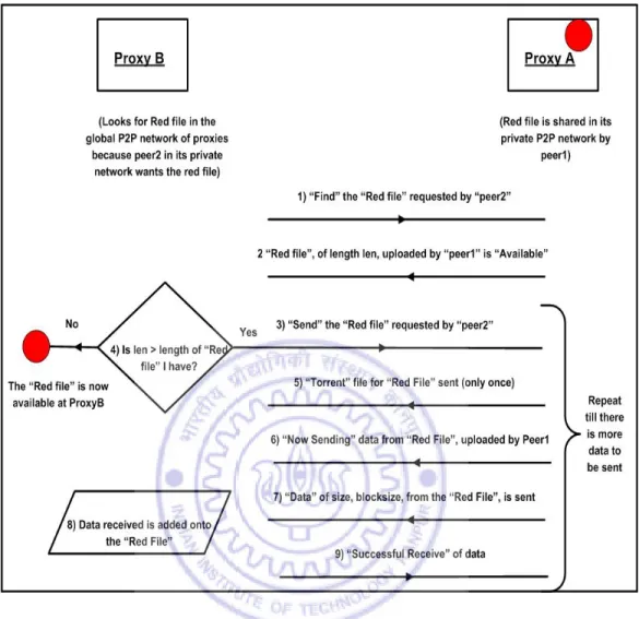
There are two main kinds of messages exchanged: control messages to acquire informa-tion about the desired content and data messages to transfer content desired by a peer. Figure 3.4 shows the sequence of messages. We shall examine each of these message types in
detail:-1. Type=Protocol We shall now look into different values which the field “Info” in the packet structure takes
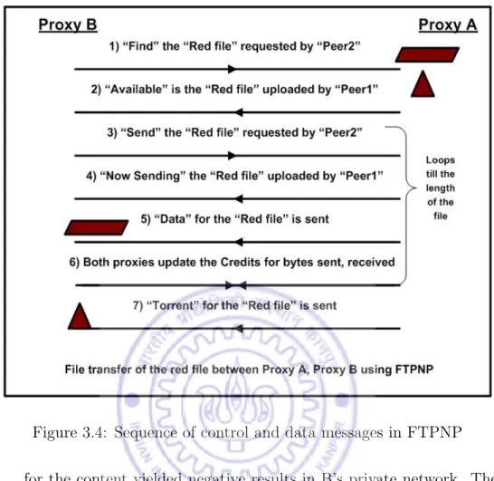
• Info=Find: This message is sent by a proxy B (see Figure 3.1) when it wishes to ask other proxy servers to search for the content whose name is given by the field “filename”. This message is initiated only when search
Figure 3.4: Sequence of control and data messages in FTPNP
for the content yielded negative results in B’s private network. The values in the fields of the packet are:
Packet Field Value
Type Protocol
Info Find
Filename name of the content being searched FP at Sending End “0”
FP at Opposite End “” (redundant field) Length “0” (redundant field) Uploading Client “” (redundant field)
Requesting Client username of requesting peer in B’s network Byte Data Array “” (redundant field)
• Info=Available: If a proxy A, has content of the same filename (uploaded by a peer in its private network) as that being searched by another proxy B (which had sent a packet with “Info” field’s value as “Find” and Filename field’s value containing the name of the content to be searched), it sends back a packet to proxy B a packet whose “Info” field has the value “Avail-able”. The values in the fields of the packet are:
Packet Field Value
Type Protocol
Info Available
Filename name of the content being searched, found FP at Sending End Size of the file at A
FP at Opposite End “0”
Length “0” (redundant field)
Uploading Client username of desired content’s uploader in A’s network Requesting Client username of requesting peer in B’s network
Byte Data Array “” (redundant field)
• Info=Send: When proxy B gets a packet whose “Info” field value is “Avail-able” from another proxy A, proxy B sends another packet to proxy A in which the “Info” field value is “Send”. The proxy B keeps sending more packets to proxy A in which the “Info” field value is “Send” and the value of the “FP at Sending End” field is updated each time to represent the po-sition of the file pointer in the currently downloaded file. The values in the fields of the packet are:
Packet Field Value
Type Protocol
Info Send
Filename name of the content being searched
FP at Sending End current length of searched content at proxy B
FP at Opposite End “FP at Sending End” field’s value in the previous packet Length “0” (redundant field)
Uploading Client username of desired content’s uploader in A’s network Requesting Client username of requesting peer in B’s network
Byte Data Array “” (redundant field)
• Info=Now Sending: When proxy A gets a packet whose “Info” field value is “Send” from another proxy B, proxy A sends another packet to proxy B in which the “Info” field value is “Now Sending”. This indicates an acknowl-edgment about the receipt of the request to send. Proxy A then starts to send data blocks to proxy B. The values in the fields of the packet are:
Packet Field Value
Type Protocol
Info Now Sending
Filename name of the content being searched
FP at Sending End current length of searched content at proxy A
FP at Opposite End value of “FP at Sending End” field in the previous packet Length “0” (redundant field)
Uploading Client username of content’s uploader in A’s network Requesting Client username of requesting peer in B’s network Byte Data Array “” (redundant field)
• Info=Successful Receive: When proxy B gets a packet whose “Type” field value is “Data”, “Info” field value is “Data” or “Torrent” from another proxy A, proxy B sends a packet to proxy A in which the “Type” field value is “Protocol”, “Info” field value is “Successful Receive”. This indicates an
acknowledgment about the receipt of data sent by proxy A to proxy B. The values in the fields of the packet are:
Packet Field Value
Type Protocol
Info Successful Receive
Filename name of the content being searched
FP at Sending End current length of searched content at proxy B
FP at Opposite End value of “FP at Sending End” field in the previous packet Length “0” (redundant field)
Uploading Client username of desired content’s uploader in A’s network Requesting Client username of requesting peer in B’s network
Byte Data Array “” (redundant field)
2. Type=Data We shall now look into different values which the field “Info” in the packet structure takes
• Info=Data: When proxy A sends a packet whose “Type” field value is “Pro-tocol”, “Info” field value is “Now Sending” it also sends another packet to proxy B in which the “Type” field value is “Data”, “Info” field value is “Data”. The proxy A takes note of the value in the field “FP at Sending End” which indicates the length of the downloaded content (content file name is “filename”) at proxy B. A decides the block size of data to be sent to B (see block size decision function in Section 3.4.2.3 below). A then cre-ates a byte data array of length equal to the blocksize and reads data from the file, “filename” starting at the position indicated by the value of the field “FP at Sending End” (in the packet which was sent by proxy B) of length equal to the block size. This data is then read into the byte-array. The values in the fields of the packet are:
Packet Field Value
Type Data
Info Data
Filename name of the content being searched
FP at Sending End current length of searched content at proxy A
FP at Opposite End “FP at Sending End” field’s value in the previous packet Length block size
Uploading Client username of desired content’s uploader in A’s network Requesting Client username of requesting peer in B’s network
Byte Data Array byte-array of content read from “filename”
When this message is received by proxy B, it reads the contents of the packet and extracts the byte-array of content. It checks if the incoming data is newer than the data already written in the file “filename”. It then writes into the file “filename” this byte-array of data starting from the cur-rent end of the file position.
• Info=Torrent: When proxy A sends a packet whose “Type” field value is “Data”, “Info” field value is “Data” it also sends another packet to proxy B in which the “Type” field value is “Data”, “Info” field value is “Torrent”, provided the value of the field “FP at Opposite End” in the data packet sent by proxy A is “0”. This message is used to send across the torrent file (whose tracker URL is the IP address of the proxy A) for the content being searched for. Thus proxy A creates a byte-array of size equal to the size of the torrent file (usually not more than a few kilobytes in size) and sends it in this packet. In this packet The values in the fields of the packet are:
Packet Field Value
Type Data
Info Torrent
Filename name of the content being searched
FP at Sending End current length of searched content at proxy A FP at Opposite End “0”
Length block size
Uploading Client username of desired content’s uploader in A’s network Requesting Client username of requesting peer in B’s network
Byte Data Array byte-array containing data read from ”filename.torrent”
When this message is received by proxy B, it reads the contents of the packet and extracts the byte-array of content. It then writes into the file “filename.torrent” this f of data starting from the current end of the file position.
3.5
Credit Management System
All P2P systems must have an incentive to share, i.e. a P2P system must guarantee better performance to those peers who share more useful content than others. In order to introduce any Quality of Service features based on the amount of data exchanged between peers, there should be book keeping of the bytes sent and received by each peer.
This component of the proxy in each private network helps to achieve the above stated goal. We shall now look at some of key design issues of this credit management system.
3.5.1
Design Issues
As stated earlier in the assumptions of the entire system (see Section 3.2) the speed of the transfer of content in the private networks is very high and the bottleneck to the performance of content transfer between two peers is the speed of the transfer of data in the top-tier global network. In this light, it was natural to think of a credit management
system for the top tier of the hierarchical network comprising proxy servers. However, if we were to build such a credit management system in which the rate of transfer of content would depend on the performance of the proxy servers in sharing frequently downloaded content, consider the following scenarios:
• Let there be a peer, peer1 in a private network pvtA, who shares a lot of useful content downloaded by not only people inpvtA, but also by several peers in other private networks. However, all the other peers inpvtAare free riders and share no useful content in pvtAor to other peers in different private networks. As a result of this, the overall utility of proxyA, the proxy of pvtA, as perceived by other proxy servers in the global P2P network will be very less. Hence poor Quality of Service shall be provided to proxyA in terms of low rates of transfer of content. Hence when any peer, peer1 included, searches for data which is unavailable in
pvtA network, data will be fetched from proxy servers of other private networks at very low rates of transfer. Thus in this scheme of credit management, peers who are sharing a lot of useful content may get unduly penalized and thus the fairness of the P2P system stands compromised.
• Conversely, consider a peer, peer1 in a private networkpvtA, which is a free-rider and does not share any content either with peers. However, the other peers in
pvtA are all conscientious peers who share lots of useful content downloaded by peers in pvtA and also by proxy servers of other private networks. As a result of this, the overall utility of proxyA, the proxy ofpvtA, as perceived by other proxy servers in the global P2P network will be very high. Hence excellent Quality of Service shall be provided to proxyA in terms of high rates of transfer of content. Hence when any peer, peer1 included, searches for data which is unavailable in
pvtAnetwork, data will be fetched from proxy servers of other private networks at very high rates of transfer. Thus in this scheme of credit management, free-riding peers, who happen to be present in a P2P network where there are benevolent peers sharing a lot of content, get undue benefits of better data transfer rates and thus the fairness of the P2P system is again compromised.
The above problems arise because there is a difference between the real end points of a transaction (peers in different P2P private networks) and the points for which the incentive mechanism is being applied (proxy servers of private networks). Hence, our credit management must take into account the real end-points of any transaction. This way, the rate of transfer of data will be governed by the past sharing behavior of the individual peers and thus there will be fairness along with an incentive to share. Let us now examine the components of the Credit Management System:
3.5.2
Components of the Credit Management System
The three components of the credit management system
are:-1. Credit Records: Each proxy maintains two vectors, the first vector, (Vec Recv), for holding information on the amount of data received from other private net-works and the other vector, (Vec Sent), for holding information on the amount of data sent to other private networks. Each Vector contains hash tables. There is one hash table for each private P2P network. For each of such hash tables (representing a private network), the keys contain names of peers in the pri-vate network. Say there are three pripri-vate networks, pvtA, pvtB and pvtC which haveproxyA,proxyB andproxyC as their respective proxy servers. SaypeerA 1,
peerA 2 are peers in pvtA; peerB 1,peerB 1 are peers in pvtB;peerC 1, peerC 2
are peers in pvtC. Then proxyAcontains
• Vec Recv, which in turn contains two hash tables, one each for pvtB and
pvtC - hashTableB, hashTableC. hashTableB contains peerB 1, peerB 2 as its keys whilehashTableC containspeerC 1,peerC 2 as its keys. The values for these keys denote the number of bytes of data received from that peer. For example, for the key peerC 1 in hashTableC contains the number of bytes of data, proxyA has received from peerC 1 peer in the pvtC.
• Vec Sent, which in turn contains two hash tables, one each for pvtB and
pvtC - hashTableB, hashTableC. hashTableB contains peerB 1, peerB 2 as its keys whilehashTableC containspeerC 1,peerC 2 as its keys. The values
for these keys denote the number of bytes of data sent to that peer. For example, for the key peerC 1 in hashTableC contains the number of bytes of data, proxyA has sent topeerC 1 peer in the pvtC.
Thus these Credit Records contain all the information about the number of bytes of data received from and sent to, for each peer in different private networks. 2. Credit Manager: This component of the proxy is called whenever the proxy
receives content from another proxy or when this proxy sends content to some other proxy.
• IfproxyAreceivesbytesC 1 bytes of data frompeerC 1, the Credit Manager addsbytesC 1 to the current value corresponding to the key,peerC 1 of the hash table, hashTableC in the vector (Vec Recv) of proxyA.
• IfproxyAsendsbytesC 1 bytes of data topeerC 1, the Credit Manager adds
bytesC 1 to the current value corresponding to the key, peerC 1 of the hash table, hashTableC in the vector (Vec Sent) ofproxyA.
3. Block Size Decision Function: The credit system is implemented through this component of the proxy. Data is transferred from one peer to another in the form of byte arrays of a certain length. The credit system is implemented as a simple prototype where the length of the byte-array in a single “Data” packet is contingent on the performance of the peer to whom the data is being sent. Say
peer2, a member of the private network, pvtB whose proxy is proxyB wishes to download content which is not available in pvtB. ProxyA has that content. In such a situation, the following happens:
• There is a fixed blocksize (base bs) of data which is the smallest length of the byte-array pushed altruistically even to free-riders.
• Each proxy calculates the utility ratio of peers belonging to other private networks, which have shared content with it. This utility ratio determines the quality of service the peer requesting for data shall receive and it depends
on the sharing history of the peer requesting for data with the proxy. In this situation, peer2is requesting for data from ProxyA. The quality of service (measured in terms of the download rate) depends on the size of the content
ProxyA has received from peer2 in the past. The utility ratio is calculated as:
utility ratio= numberof bytesreceivedbyP roxyAf rompeer2
totalnumberof bytesreceivedbyP roxyA (3.1)
• There is a maximum incentive blocksize (incentive bs), a part of which is added to the base blocksize depending upon the utility ratio of the peer in the past.
• The block size of data to be sent, (final blocksize), is calculated as
f inal blocksize=base bs+incentive bs∗utility ratio (3.2) This function ensures that peers who share more data get better performance because they get a larger size of the byte-array of content in every “Data” packet.
3.6
Working of the Hierarchical P2P Network
We shall now give an overview of the two main components of the working of the Hierarchical P2P Network, namely, file sharing and file download.
3.6.1
File Sharing
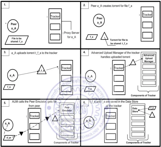
Say a peer peer1, in a private network pvtA whose proxy is proxyA, wishes to share a file fileA with other peers inpvtA. Following are the steps involved in the sharing (see Figure 3.5):
• peer1 creates a torrent file torrentA for fileA with proxyA as the tracker URL.
• peer1 logs into the tracker atproxyAand uses the web interface to uploadtorrentA
Figure 3.5: Algorithm to share a file
• peer1 then opens the torrent file with the BitTorrent Client software on its ma-chine and starts seeding the torrent.
• The Advanced Upload Manager(see section 3.3.1.2) of the tracker atproxyA
comes into action. It makes torrentA available for download to all registered peers. It inserts torrentA in the database of torrents and enlists peer1 as the uploader of this content. This Advanced Upload Manager then, using the Peer Emulatorfunctionality of the tracker atproxyA, runstorrentAon the BitTorrent
client software at the tracker and using BitTorrent downloads the file from peer1
onto proxyA’s Data Store.
. Thus when a peer uploads a torrent file onto its private network’s tracker, the tracker opens the uploaded torrent using its BitTorrent Client software and downloads the file itself. The torrent becomes visible to other peers in the private network and the shared file becomes downloadable.
3.6.2
File Download
There are two situations which need to be considered in case of downloading files:
3.6.2.1 Requested file is in the same private network
Consider a private network pvtA in which there are two peers, peer1 and peer2. Peer2
shares a file, fileA using the method described in Section 3.4.1 above. Peer1 wishes to download fileA.
• peer1 searches for fileA’s torrent on the tracker in the proxy proxyA.
• The search is successful and it returns the torrent, torrentA which had been uploaded by peer2.
• peer1 downloadstorrentAand opens it using its BitTorrent Client software which contacts the tracker in proxyA.
• The tracker then coordinates the download of fileA frompeer2 to peer1.
3.6.2.2 Requested file is in another private network
Say there are three private networks pvtA, pvtB and pvtC whose proxy servers are
proxyA, proxyB and proxyC respectively. These proxy servers form a global network. Say peer1 belongs topvtAandpeer2 belongs topvtB.Peer1 is sharing a file,fileAwith all peers in its private network, pvtAand has uploaded torrentA (torrent file forfileA) on the tracker in proxyA. Peer2 inpvtB wishes to download the file fileA but no peer in pvtB is sharing fileA. No peer in pvtC is sharing fileA.
• peer2 searches for the torrent for fileAon the tracker in proxyB. Since no peer in
pvtB is sharing fileA, this search yields negative results.
• Since search for content in the private network was unsuccessful, the top tier of the hierarchical P2P network comes into play and now the content is searched for in the global P2P network of proxy servers pvtA, pvtB and pvtC.
• Proxy pvtB sends a Protocol packet each to other peers in the global P2P network (pvtA and pvtC) asking them to “Find” fileA for peer2.
• Each of the proxy servers, proxyA and proxyC checks in their“Data Store” in order to find fileA.
• ProxyC does not have the required file and so it does not respond back to the “Find” query.
• Since peer1 had shared fileA in the private networkpvtA, the “Data Store” of
proxyA contains fileA and torrentA (torrent file for fileA).
• ProxyAsends aProtocolpacket back toproxyB saying thatfileAis“Available”
with it as fileA had been shared bypeer1 in the private network pvtA.
• ProxyB then sends another Protocol packet to proxyA and asks the latter to
“Send” data fromfileA starting fromfile pointer position at zero.
• ProxyAthen sends anotherProtocolpacket toProxyB informing the latter that it is “Now Sending” data from fileA, which had been uploaded by peer1 in
pvtA, starting from file pointer position at zero forpeer2 in pvtB.
• Thus both proxyAandproxyB know that transfer of data is occurring frompeer1
(belonging to pvtA) peer2 (belonging topvtB).
• proxyA then uses the “block size decision function”to calculate the “block-size” of the data to be sent to proxyB. It also updates its “Credits Record”
• ProxyA then sends a “Data” packet to proxyB containing “Data” from fileA
starting from file pointer position at zero. This data is sent in the form of a
“byte data array” whose length is given by the “blocksize” determined above.
• ProxyB too updates its “Credits Record” using the “Credit Manager”.
• ProxyA then sends another “Data” packet to proxyB containing data from the“Torrent” file of fileA,torrentA stored in the “byte data array”.
• ProxyB then sends anotherProtocolpacket toProxyAinforming the latter of the
“Successful Receive” of data from fileA starting from file pointer position
at zero.
• ProxyB continues to repeatedly send “Protocol” packets to proxyA, asking the latter to “Send” data from fileA starting from “file pointer position” equal to the length of fileA downloaded at proxyB.
• Each time proxyAreceives a request to “Send”, it sends a “Now Sending” packet followed by a “Data” packet. The “byte data array” contains data from fileA of length determined by the “block size decision function”. Data is read from fileA
from file pointer position given by the length of the fileA downloaded currently at proxyB.
• After each transfer of data, the “Credit Manager” at each of the proxy servers, updates the “Credits Record” for their particular proxy (See Figure 3.6).
• ProxyB continues to ask for more data fromproxyAuntil finally, when the length of fileA atproxyB stops to increase. Thus nowfileA and its torrent file, torrentA
are present at the “Data Store” of proxyB.
• torrentA atproxyB is the same torrent file which had been uploaded at proxyA, and hence the tracker URL oftorrentA is the URL of proxyA. Hence, this torrent cannot uploaded directly at the tracker in proxyB. To resolve this the “Torrent Manipulator” component of the tracker is called. This changes the tracker
Figure 3.6: (a)The structure of the Credit Records at each Proxy. (b)The updation of credit records when file transfer occurs between two proxies
URL originally present in torrentA to the URL of proxyB, inserts torrentA into the torrent database and uploads the new modified torrentA on the tracker.
• Hence, through the “Peer Emulator” and the “Auto Torrent