Refinement of the Microstructure of Light Alloys
using Ultrasonic and Laser Processing
A thesis submitted in fulfilment of the requirements of the degree of Doctor of Philosophy
Carmelo J. Todaro
B. Eng. (RMIT University)
School of Engineering
College of Science, Engineering and Health RMIT University
II
Declaration
I certify that except where due acknowledgement has been made, the work is that of the author alone; the work has not been submitted previously, in whole or in part, to qualify for any other academic award; the content of the thesis/project is the result of work which has been carried out since the official commencement date of the approved research program; any editorial work, paid or unpaid, carried out by a third party is acknowledged; and, ethics procedures and guidelines have been followed. I acknowledge the support I have received for my research through the provision of an Australian Government Research Training Program Scholarship.
Carmelo J. Todaro 05 March 2019
III
Dedication
To my nonna Anna Bartolotta, whose love, sacrifices and support will inspire me forever.
IV
Acknowledgements
This research was supported the Australian Research Council (ARC) Discovery Projects DP150104719 and DP140100702 and the ExoMet Project co-funded by the European Commission’s7th Framework Programme (contract FP7-NMP3-LA-2012-280421), by the European Space Agency and by the individual partner organizations.
I offer my sincerest gratitude to my primary supervisor Professor Ma Qian for providing me the opportunity to undertake this work. I have been blessed to have his guideline, support and assistance. I also extend my appreciation to my secondary supervisors Professor Mark Easton and Professor David StJohn for their suggestions, discussions and encouragement.
I acknowledge both the Microscopy and Microanalysis Facility (RMMF) and the Advanced Manufacturing Precinct (AMP) at RMIT University for their facilities and technical assistance.
Lastly, this thesis could not have been written without the support of my family. I thank them for their unconditional love and encouragement.
V
Executive Summary
The transport sector represents 20 pct of all greenhouse gas emissions globally. The use of aluminum (Al) to reduce vehicle weight offers the potential to reduce these emissions. The production of secondary Al from recycled products requires only ~2.8 kWh kg-1 compared to ~45 kWh kg-1 for primary Al production. In addition, recycling emits only ~5 pct as much carbon dioxide as primary production. Hence, the environmental advantages of using recycled Al for transport applications are as attractive as the economic savings. Unfortunately, the properties of recycled Al alloys do not meet the necessary requirements due to the unavoidable introduction of iron (Fe) impurity that leads to the occurrence of harmful Fe-containing intermetallic compounds (IMCs). This thesis aims to establish the knowledge required to be able to increase the utilization of recycled Al by controlling the formation of the Fe-containing IMCs by ultrasonic melt treatment (USMT). In addition, USMT was further extended to laser additive manufacturing (LAM) to explore its applicability for structural refinement.
• Ultrasonic melt treatment (USMT) of an Al-19Si-4Fe alloy
USMT was used to control the formation of Fe-containing IMCs in an Al-19Si-4Fe alloy (all alloy compositions are given in wt pct unless otherwise indicated). Macrostructural examination revealed that the ingot in the absence of USMT had a considerable non-uniform distribution of primary Fe-containing IMCs, whereas the ingot with USMT exhibited a near homogeneous distribution of the IMCs, i.e., reduced macro-segregation. Statistical analyses based on quantitative metallography confirmed
VI
that the area fraction, number density and size distribution of the Fe-containing IMCs became essentially uniform across the ingot with USMT. In addition, USMT further exerted an unexpected impact on the constitution of the primary Fe-containing IMCs. Complex δ-Al3FeSi2/β-Al5FeSi IMCs were prominent without USMT while few δ-Al3FeSi2 IMCs were observed after USMT and the primary Fe-containing IMCs existed mostly as single-phase β-Al5FeSi IMCs. Such observations indicate that USMT furthered the peritectic transformation δ-Al3FeSi2→ β-Al5FeSi. The underlying reasons were identified.
• USMT of a manganese (Mn)-modified Al-17Si-2Fe alloy
The individual and combined effects of different levels of Mn addition and USMT on the formation of Fe-containing IMCs in an Al-17Si-2Fe alloy were investigated. Increasing the Mn content without USMT resulted in macro-segregation and coarse IMCs. In addition, not all δ-Al3FeSi2/β-Al5FeSi IMCs transformed into the desirable α-Al15(Fe,Mn)3Si2 phase. In contrast, the combination of USMT and Mn addition avoided all these issues. The resultant microstructure was featured by fine dispersed polyhedral α-Al15(Fe,Mn)3Si2 IMCs. The volume fraction of the IMCs was quantified and compared with predictions made from the Scheil equation and the lever rule. The underlining mechanisms for the effect of Mn and USMT on Fe-containing IMC formation and the effect of USMT alone on the Fe-containing IMC selection were discussed and proposed.
VII
• Laser processing of an Al-19Si-4Fe alloyA systematic study has been made on the Fe-containing IMC formation in a laser processed Al-19Si-4Fe alloy. The microstructure of the laser re-melted Al-19Si-4Fe alloy consisted of a three-dimensional (3D) architecture of fine interconnected co-eutectic platelet-like δ-Al3FeSi2 IMCs. Consequently, the laser re-melted Al-19Si-4Fe alloy exhibited a superior yield stress and tensile strength than commercial hypereutectic Al-Si alloys without compromising ductility. The experimental data produced provide new perspectives on the development of Fe-modified hypereutectic Al-Si based alloys for LAM.
• USMT during laser additive manufacturing (LAM)
Structural refinement of LAM-fabricated Ti-6Al-4V by USMT was investigated. Ti-6Al-4V was selected as a feedstock powder due to its readier availability compared to Fe-modified hypereutectic Al-Si alloy feedstock powder. The sample without USMT consisted of large (>500 µm) columnar (aspect ratio > 2.5) prior-β grains traversing multiple deposited layers. In contrast, fine (~100 µm) essentially fully equiaxed grains were obtained in the sample with USMT. The sample with USMT showed a 12 pct improvement in both the yield stress and tensile strength compared to the sample without USMT. Assessment of the ultrasonic conditions during LAM revealed that the selection of the ultrasonic transducer element is an important practical consideration for grain refinement by USMT and a solution was recommended. The most likely responsible grain refinement mechanism was discussed. This approach can be extended
VIII
to other alloy systems for structural refinement, including Fe-modified Al-Si based alloys.
Keywords: Hypereutectic Al-Si alloys; Fe-containing intermetallic compounds; Ultrasonic melt treatment; Laser processing, Solidification processing.
IX
Table of Contents
Executive Summary ... V List of Figures ... XIII List of Tables ...XXIII Publications Related to Thesis Chapters ... XXV
Chapter 1: Introduction ... 1
1.1 Background ... 1
1.2 Aim and Objectives ... 3
1.3 Thesis Outline ... 4
Chapter 2: Literature Review ... 5
2.1 Aluminum-Silicon Alloys ... 5
2.2 Hypereutectic Aluminum-Silicon Alloys ... 8
2.3 Composition of Hypereutectic Aluminum-Silicon Alloys ... 9
2.4 Iron in Aluminum... 14
2.5 Iron-Containing Intermetallic Compounds in the Aluminum-Iron-Silicon System ... 18
2.6 Nucleation and Growth of Iron-Containing Intermetallic Compounds .. 21
2.7 The Role of Iron-Containing Intermetallic Compounds on Mechanical Properties ... 27
2.8 Modifying the Iron-Containing Intermetallic Phases ... 32
2.8.1 Chemical Means ... 32
2.8.2 Thermal Treatments ... 38
2.8.2.1
Cooling Rate... 38
2.8.2.2
Melt Superheating ... 42
2.8.3 Ultrasonic Melt Treatment ... 44
2.9 Summary and Research Gaps Identified ... 50
Chapter 3: Ultrasonic Melt Treatment of an Al-19Si-4Fe Alloy... 54
X
3.2 Introduction ... 55
3.3 Experimental ... 61
3.3.1 Materials ... 61
3.3.2 Ultrasonic Melt Treatment Procedure ... 61
3.3.3 Characterization ... 63
3.4 Results ... 64
3.4.1 Cooling Curves ... 64
3.4.2 Macrostructure ... 67
3.4.3 Microstructure ... 69
3.4.4 Quantitative Microstructural Analysis ... 72
3.4.5 Complex Iron-Containing Intermetallic Compounds ... 76
3.5 Discussion ... 81
3.5.1 Macro-Segregation... 81
3.5.2 Peritectic Transformation ... 82
3.6 Conclusions ... 87
Chapter 4: Ultrasonic Melt Treatment of a Manganese-Modified Al-17Si-2Fe Alloy ……….88
4.1 Brief Summary ... 88
4.2 Introduction ... 88
4.3 Experimental ... 91
4.3.1 Materials ... 91
4.3.2 Ultrasonic Melt Treatment Procedure ... 91
4.3.3 Characterization ... 92
4.4 Results ... 94
4.3.1 Microstructure ... 94
4.3.2 Quantitative Microstructural Analysis ... 99
4.3.3 Identification of Iron-Containing Intermetallic Compounds ... 103
4.3.4 Thermodynamic Predictions ... 112
4.3.5 Comparison with Predictions ... 115
XI
4.5.1 Iron-Containing Intermetallic Compound Formation ... 117
4.5.2 Iron-containing Intermetallic Compound Selection ... 118
4.6 Conclusions ... 120
Chapter 5: Laser Re-Melting of an Al-19Si-4Fe Alloy ... 122
5.1 Brief Summary ... 122 5.2 Introduction ... 122 5.3 Experimental ... 125 5.3.1 Materials ... 125 5.3.2 Characterization ... 125 5.3.3 Mechanical Testing ... 126 5.4 Results ... 127 5.4.1 Microstructure ... 127
5.4.2 3D Morphology of Fe-Containing IMC Particles ... 131
5.4.3 Mechanical Properties ... 133
5.5 Discussion ... 135
5.5.1 As-Cast Alloys ... 135
5.5.2 Laser Re-Melted Alloys ... 136
5.6 Conclusions ... 137
Chapter 6: Grain structure control during metal 3D printing by high intensity ultrasound.. ... 138 6.1 Brief Summary ... 138 6.2 Introduction ... 139 6.3 Experimental ... 142 6.3.1 Materials ... 142 6.3.2 Characterization ... 144 6.3.3 Tensile Testing ... 145 6.4 Results ... 146 6.4.1 Ultrasound during AM ... 146 6.4.2 Macrostructure ... 147 6.4.3 Microstructure ... 149
XII
6.4.4 Tensile Properties ... 154
6.4.5 Extension to further alloy systems ... 156
6.5 Discussion ... 157
6.5.1 Ultrasonic Conditions ... 157
6.5.2 Grain Refinement Mechanism ... 160
6.6 Conclusions ... 163
Chapter 7: Summary and Future Work ... 164
7.1 Summary ... 164
7.2 Recommendations for Future Work ... 167
XIII
List of Figures
Fig. 2.1: The Al-Si phase diagram [22]. ... 6 Fig. 2.2: Typical microstructures of (a) hypoeutectic [23] and (b) hypereutectic [24] Al-Si alloys. ... 7 Fig. 2.3: Porsche 928 engine block by 390 alloy low-pressure casting [25]. ... 9 Fig. 2.4: The Al-Fe phase diagram [28]. ... 14 Fig. 2.5: Al corner of the Al-Fe-Si diagram [27]: (a) liquidus and (b) phase distribution in the solid. ... 15 Fig. 2.6: (a) Three dimensional (3D) reconstruction of a group of platelet β-Al5FeSi IMCs in the outlined region in (b) [30]. (c) Micrographs of fractured platelet β-Al5FeSi IMCs in a tested tensile specimen of an Al-5Si-1Cu based alloy [32]... 17 Fig. 2.7: Scanning electron microcopy (SEM) image showing a δ-Al3FeSi2 IMC enveloped by a β-Al5FeSi IMC due to an incomplete peritectic transformation [48]. . 20 Fig. 2.8: (a) 3D reconstruction of an α-Al15(Fe,Mn)3Si2 IMC in the outlined region in (b) [30]. ... 21 Fig. 2.9: Entrainment of oxides at the melt surface [53]. ... 22 Fig. 2.10: (a) SEM backscattered image showing an oxide crack in an α-Al15(Fe,Mn)3Si2 IMC and the Al matrix and (b) SEM image showing the gap between the two inner dry sides of the oxide crack [55]. ... 23 Fig. 2.11: Reconstructed β-Al5FeSi IMCs in the entire sample of an Al-8Si-4Cu-0.8Fe alloy imaged by synchrotron X-ray tomography showing four nucleation events (A-D) initiated at the outer oxide surface [58]. ... 24
XIV
Fig. 2.12: Quantified β-Al5FeSi IMC nucleation rates in an Al-7.5Si-3.5Cu-0.6Fe alloy for different nucleation mechanisms [59]. ... 25 Fig. 2.13: AlP particles associated with a β-Al5FeSi IMC in an Al-6Si-3.5Cu based alloy [62]. ... 26 Fig. 2.14: 3D tomographs showing the pore evolution (blue) in the presence of Fe-containing IMCs (red) at (a) 565 °C, (b) 561 °C, (c) 555 °C and (d) 550 °C [85]. Note the pore growth along the solid surface of Fe-containing IMCs in the dashed circles. ... 29 Fig. 2.15: The porosity level versus Fe content in an Al-Si-Cu based alloy [70]. ... 30 Fig. 2.16: (a) Optical micrograph showing an oxide crack in a β-Al5FeSi IMC in an Al-Si based alloy [81]. (b) is a higher magnification optical micrograph of (a). ... 31 Fig. 2.17: SEM backscattered images showing the effect of different levels of Mn content on the formation of Fe-containing IMCs in an Al-Si-Cu based alloy. (a) 0.02 pct Mn, (b) 0.3 pct Mn, (c) 0.65 pct Mn and (d) 0.85 pct Mn [101]. ... 34 Fig. 2.18: SEM image showing the occurrence of sludge α-Al15(Fe,Mn)3Si2 IMCs in an Al-11.5Si-0.4Mg based alloy [112]. ... 36 Fig. 2.19: The relationship between DAS and the length of β-Al5FeSi IMCs in an Al-7Si-0.3Mg based alloy [66]. The cooling rate is supplemented according to the relationship given in [123]. ... 39 Fig. 2.20: Optical micrograph showing the microstructure of a rapidly solidified Al-20Si-5Fe-3Cu-1Mg alloy [124]. ... 40
XV
Fig. 2.21: (a) SEM image of a rapidly solidified Al-20Si-5Fe-3Cu-1Mg alloy and (b) the same alloy with the addition of 3 pct Mn [129]. ... 41 Fig. 2.22: The change in Fe-containing IMCs in an Al-20Si-2Fe based alloy with different USMT times: (a) 0 s, (b) 60 s, (c) 120 s, and (d) 180 s [8]. ... 47 Fig. 2.23: Grain refinement of magnesium alloy AZ31 welds by high-intensity ultrasound. (a) A weld treated with ultrasound by pushing an ultrasound sonotrode into the melt pool. (b, c) Polarized light microscopy images of samples (b) without and (c) with ultrasound (frequency: 20 kHz, ultrasound amplitude: 26.44 µm). Coarse columnar grains are converted to fine (46 µm) equiaxed grains by ultrasound. Adapted from Ref. [17]. ... 49 Fig. 3.1: Schematic illustration of the experimental set-up. ... 62 Fig. 3.2: Temperature vs fraction solid curve as predicted by PANDATTM assuming equilibrium solidification of the Al-19Si-4Fe alloy. ... 64 Fig. 3.3: Cooling curves and their first derivatives for the Al-19Si-4Fe alloy: (a) without USMT and (b) with USMT. ... 65 Fig. 3.4: (a) Vertical section of a solidified Al-19Si-4Fe ingot without USMT and (b) the same alloy with USMT. Note the distinct difference in macro-segregation and phase distribution in (a) and (b). ... 69 Fig. 3.5: SEM BSE micrographs showing the typical primary phase structures in the four different zones of the Al-19Si-4Fe ingots shown in Fig. 3.4... 71
XVI
Fig. 3.6: Area fraction of primary phases without and with USMT in the ingot samples shown in Fig. 3.4: (a) primary Fe-containing IMCs, and (b) primary Si. Refer to Fig. 3.4 for the different zones. ... 73 Fig. 3.7: Number density of primary phases without and with USMT for the ingot samples shown in Fig. 3.4: (a) primary Fe-containing IMCs, and (b) primary Si. Refer to Fig. 3.4 for the different zones. ... 74 Fig. 3.8: Morphological parameters of primary phases for the alloy ingots shown in Fig. 3.4: (a) primary Fe-containing IMCs without USMT; (b) primary Fe-containing IMCs with USMT; (c) primary Si without USMT; and (d) primary Si with USMT. Refer to Fig. 3.4 for the different zones. ... 75 Fig. 3.9: (a) Typical BSE image showing unreacted platelet-like Fe-containing IMCs existing as complex particles of δ-Al3FeSi2/β-Al5FeSi in Zone I of the ingot sample solidified without USMT, and (b) an enlarged view. ... 77 Fig. 3.10: BSE images showing examples of primary Fe-containing IMCs: (a through c) complex blocky particles of δ-Al3FeSi2/β-Al5FeSi observed near the mold wall regions of the ingot samples solidified without USMT; (d, e) single-phase short IMCs observed in the ingot after USMT; and (f) a complex particle of δ-Al3FeSi2/β-Al5FeSi observed in the ingot sample with USMT. ... 78 Fig. 3.11: EDS line scans across selected Fe-containing IMCs: (a) the complex particle in Fig. 3.9c; (b) the complex particle in Fig. 3.9f; and (c) the single-phase β-Al5FeSi particle in Fig. 3.9e. ... 79
XVII
Fig. 3.12: Schematic diagram showing the effect of USMT on the peritectic transformation δ-Al3FeSi2 → β-Al5FeSi. The finer primary δ-Al3FeSi2 particles produced as a result of USMT ensure their complete transformation into peritectic β-Al5FeSi phase. ... 86 Fig. 4.1: Illustration of the experimental set up consisting of: (1) ultrasonic transducer; (2) ultrasonic waveguide; (3) ultrasonic sonotrode; (4) crucible; (5) melt; (6) insulation; (7) ultrasonic generator; (8) thermocouple and (9) movable stand. ... 94 Fig. 4.2: Macrostructures of the Al-17Si-2Fe alloy (a) without and (b) with USMT. The top (I), middle (II) and bottom (III) regions of the alloy without USMT are indicated by the dashed lines. ... 96 Fig. 4.3: SEM BSE micrographs of Al-17Si-2Fe-xMn alloys without USMT. (a, a’) x = 0 pct, (b, b’) x = 0.5 pct, (c, c’) x = 1 pct, (d, d’) x = 1.5 pct and (e, e’) x = 2 pct. The left- and right-side micrographs were taken from the top (Region I, Fig. 4.2a) and central (Region II, Fig. 4.2a) region of each ingot, respectively. ... 97 Fig. 4.4: SEM BSE micrographs taken from the bottom region of the Al-17Si-2Fe-xMn alloy ingots without and with USMT. (a, a’) x = 0 pct, (b, b’) x = 0.5 pct, (c, c’) x = 1 pct, (d, d’) x = 1.5 pct and (e, e’) x = 2 pct. The left- and right-side micrographs are alloys without and with USMT, respectively. ... 98 Fig. 4.5: Size distributions of primary Si particles in the Al-17Si-2Fe-xMn alloy ingots without and with USMT. (a) x = 0 pct, (b) x = 0.5 pct, (c) x = 1 pct, (d) x = 1.5 pct and (e) x = 2 pct. ... 100
XVIII
Fig. 4.6: Size distributions of the primary Fe containing IMCs in the Al-17Si-2Fe-xMn alloy ingots without and with USMT. (a) x = 0 pct, (b) x = 0.5 pct, (c) x = 1 pct, (d) x = 1.5 pct and (e) x = 2 pct. ... 101 Fig. 4.7: Number densities of (a) primary Si particles and (b) of the primary Fe-containing IMCs in the five alloy ingots without and with USMT. ... 103 Fig. 4.8: SEM BSE micrographs and EBSD phase mapping of typical Fe-containing IMCs in the five alloys without USMT. (a) Duplex platelet, (b) duplex blocky, (c) single-phase blocky and (d) star-like. ... 107 Fig. 4.9: SEM BSE micrographs and EBSD phase mapping of typical Fe-containing IMCs in the five alloys with USMT. (a) Single-phase rod-like, (b) duplex rod-like and (c) polyhedral. ... 107 Fig. 4.10: Example of EBSD phase mapping at low magnification: (a, b) SEM BSE micrograph of the Al-17Si-2Fe-1Mn alloy without and with USMT, respectively. (c, d) The corresponding EBSD phase maps showing δ-Al3FeSi2 (red), β-Al5FeSi (blue) and α-Al15(Fe,Mn)3Si2 (green). ... 109 Fig. 4.11: Isopleth of the equilibrium Al-Fe-Si-Mn phase diagram at 17 pct Si, 2 pct Fe and with variation of Mn content. ... 113 Fig. 4.12: The experimentally measured Fe-containing IMC volume percentages in the bottom region of each alloy ingot (a) without and (b) with USMT compared with predictions made from the Scheil equation and the lever rule. Direct comparison between the measured values for the alloys without USMT with the predictions is
XIX
unsuitable due to macro-segregation. For fair comparison, the IMC fractions were normalized with respect to the total fraction of IMCs for the corresponding alloy. .. 116 Fig. 5.1: Extraction of a micro-flat tensile specimen (12 mm gauge length, 2 mm width and 0.5 mm thickness) for determining the local tensile properties of the laser re-melted alloy. ... 127 Fig. 5.2: Laser processing of the Al-19Si-4Fe alloy. (a, b) XRD spectra collected from the cast (a) and laser processed (b) alloy (labels: Al = α-Al, Si = silicon and δ = δ-Al3FeSi2). (c) SEM BSE image of the polished cross section of the laser processed alloy. (d, e) SEM BSE images taken from the center of the laser processed region shown in (c). ... 129 Fig. 5.3: Analysis of Fe-containing IMC particles within the interdendritic spaces of the laser processed Al-19Si-4Fe alloy. (a-e) STEM analysis including bright-field (BF)-STEM image (a) and corresponding EDS mapping for overlaid Al, Si and Fe (b), Al (c), Si (d) and Fe (e). (f) EDS line profile generated along the arrow in (a). ... 130 Fig. 5.4: 3D reconstruction of Fe-containing intermetallic particles in the Al-19Si-4Fe alloy samples. (a) Optical tomography image of the Fe-containing IMCs in the cast alloy. (b) FIB-SEM tomography image of the Fe-containing IMCs in the laser processed alloy. (c) show an Fe-containing IMC extracted from the volume in (b). ... 132 Fig. 5.5: Effect of laser processing on the mechanical response of the Al-19Si-4Fe alloy. (a) Microhardness distribution measured horizontally along the re-melted region of the laser processed sample. (b) Tensile engineering stress-stain curves of the cast and laser processed samples. ... 134
XX
Fig. 6.1: Cross-sectional schematic showing metal AM by laser-based DED onto an ultrasonic sonotrode vibrated at 20 kHz. The formation of acoustic cavitation and streaming in the liquid metal by high-intensity ultrasound can vigorously agitate the melt during solidification, thereby promoting significant structural modification or refinement. ... 147 Fig. 6.2: Grain refinement of the AM-fabricated Ti-6Al-4V by high-intensity ultrasound. (a, b) Optical microscopy images of the samples (a) without and (b) with ultrasound. (c, d) Polarized light microscopy images showing (c) large columnar grains and (d) fine equiaxed grains. (e, f) Histograms of the (e) prior-β grain size and (f) prior-β grain aspect ratio for the samples without and with ultrasound measured from traced prior-β grain images. The prior-β grain boundaries in (c) and (d) are traced in white. Scale bars, 1 mm. ... 149 Fig. 6.3: Microstructure characterization of the AM-fabricated Ti-6Al-4V without and with high-intensity ultrasound. (a-d) SEM images showing the α-β structure inside the prior-β grains of the samples (a, c) without and (b, d) with ultrasound. (e, f) Histograms of the α-lath thickness of the samples (e) without and (f) with ultrasound. The prior-β grain boundaries in (a) and (b) are traced in white. Scale bars, 50 μm in (a, b), 5 μm in (c, d). ... 151 Fig. 6.4: Texture changes in AM-fabricated Ti-6Al-4V by high-intensity ultrasound. (a, c) Inverse pole figure maps along the build direction (z) for the α phase (measured by EBSD) in samples (a) without and (c) with ultrasound. (b, d) Inverse pole figure maps along the build direction (z) for the β phase (reconstructed from the α phase maps
XXI
in (a) and (c)) in samples (b) without and (d) with ultrasound. (e, f) {0001} contoured pole figures of the measured α phase in samples (e) without and (f) with ultrasound. (g, h) {001} contoured pole figures of the reconstructed β phase in samples (g) without and (h) with ultrasound. Black lines in (b) and (d) indicate high angle grain boundaries (misorientation >10°). Scale bars, 250 μm. ... 153 Fig. 6.5: Tensile properties of AM-fabricated Ti-6Al-4V. (a) Engineering stress-strain curves of the as-built samples without and with ultrasound. The error bars are standard deviations of the mean for three tests. (b) Change in yield stress of AM-fabricated Ti-6Al-4V by chemical addition [268, 269] compared to ultrasound in this work. (c) Tensile yield stress with the inverse of square root of prior-β grain size from the literature [231, 232, 239, 244, 245, 248, 270-274] and this work. The solid line in (c) represents the line of best fit while the dashed lines define ± 0.15σ0 along the linear fit. ... 155 Fig. 6.6: AM of Inconel 625 with and without high-intensity ultrasound. (a, b) Inverse pole figure maps along the build direction (z) for the γ phase in samples (a) without and (b) with ultrasound. (c, d) {001} contoured pole figures of the γ phase in samples (c) without and (d) with ultrasound. (e) Inverse pole figure map along the build direction (z) of a sample fabricated by turning the ultrasound on and off during AM. Scale bars, 250 μm. ... 157 Fig. 6.7: High-intensity ultrasound conditions during AM of Ti-6Al-4V. (a) Change in amplitude by Eq. 6.2 versus the vertical axis of the acoustic system. (b) Change in intensity by Eq. 6.3 versus build height. The red dashed line in (b) corresponds to the
XXII
intensity required to overcome the cavitation threshold in molten light metals (Ic ≥ 100 W cm-2 [144]). The gray regions in (b) denote when cavitation is non-operative. ... 160
XXIII
List of Tables
Table 2.1: Nominal composition of some commercial hypereutectic Al-Si alloys. .... 12 Table 2.2: Missing gaps in the literature and their respective hypotheses and importance. ... 52 Table 3.1: Previous studies on USMT of hypereutectic Al-Si based alloys containing deliberate additions of Fe. The abbreviation NS stands for not specified. ... 58 Table 3.2: Solidification reactions observed from the thermal analysis diagrams of the Al-19Si-4Fe alloy without and with USMT. ... 66 Table 3.3: EDS point analysis results of primary Fe-containing IMCs. ... 80 Table 3.4: The average IMC half-width (critical diffusion length) and the average thickness of the peritectic β-Al5FeSi phase envelope in the alloy without and with USMT. ... 86 Table 4.1: Compositions of the five alloys determined by inductively coupled plasma atomic emission spectroscopy (ICP-AES). ... 93 Table 4.2: The average equivalent size, standard deviation (SD) and standard error (SE) of the primary Si and primary Fe-containing IMCs in the five alloys without and with USMT. Data taken from Fig. 4.5 and 4.6. ... 102 Table 4.3: EDS and EBSD identification of the primary Fe containing IMCs in the alloys without and with USMT. ... 106 Table 4.4: EBSD phase mapping results near the bottom of the alloy ingots without and with USMT, showing the average pct of the Fe-containing IMCs. Standard deviations are listed in parentheses. ... 110
XXIV
Table 4.5: Calculated volume fraction of Fe-containing IMCs at the end of solidification of the five alloys as predicted by the Scheil equation and the lever rule. ... 114 Table 5.1: The tensile properties of the as-cast and laser re-melted Al-19Si-4Fe alloy in this work compared to some commercial hypereutectic Al-Si alloys. ... 135 Table 6.1: Compositions of Ti-6Al-4V without and with USMT determined by ICP-AES and LECO combustion. ... 144
XXV
Publications Related to Thesis Chapters
Chapter 2: D. Zhang, A. Prasad, M.J. Bermingham, C.J. Todaro, M.J. Benoit, M. Patel, D. Qiu, D.H. StJohn, M. Qian, M.A. Easton, Grain refinement of alloys in additive manufacturing processes, Metallurgical and Materials Transactions A (2020) (under review)
Chapter 3: C.J. Todaro, M.A. Easton, D. Qiu, G. Wang, D.H. StJohn, M. Qian, The effect of ultrasonic melt treatment on macro-segregation and peritectic transformation in an Al-19Si-4Fe alloy, Metallurgical and Materials Transactions A 48a(11) (2017) 5579-5590.
Chapter 4: C.J. Todaro, M.A. Easton, D. Qiu, G. Wang, D.H. StJohn, M. Qian, Effect of ultrasonic melt treatment on intermetallic phase formation in a manganese-modified Al-17Si-2Fe alloy, Journal of Materials Processing Technology 271 (2019) 346-356.
Chapter 6: C.J. Todaro, M.A. Easton, D. Qiu, D. Zhang, M.J. Bermingham, E.W. Lui, M. Brandt, D.H. StJohn, M. Qian, Grain structure control during metal 3D printing by high-intensity ultrasound, Nature Communications 11(1) (2020) 142.
1
Chapter 1:
Introduction
1.1
Background
A recycling-based society requires the use of recycled material for the production of metal alloy components. A major practical issue in the aluminum (Al) industry is the unavoidable introduction of impurities from the Al scrap into the raw material during the recycling process. Impurities may include chromium (Cr), copper (Cu), iron (Fe), lead (Pb), magnesium (Mg), manganese (Mn), molybdenum (Mo), nickel (Ni), silicon (Si), vanadium (V), zinc (Zn) and zirconium (Zr) [1]. These elements cannot be economically removed from the Al and tend to increase modestly with each recycling event. Of these impurity elements, Fe is considered the most deleterious and important in Al alloys. This is because it promotes the formation of Fe-containing intermetallic compounds (IMCs) that increase material defects, reduce the mechanical properties and lead to inconsistent performance of the component [2-5].
The development of higher performance Al engines with increased combustion pressures and temperatures is ongoing due to stricter fuel economy standards. Unfortunately, the strength of all commercial Al alloys decreases rapidly with increasing temperature and increasing soaking time above 150 °C [6]. This is due to the thermal instability of the precipitation hardening phases in these alloys, such as Al2Cu phase, Q phase, Mg-Si phases. Therefore, new cost-effective Al alloys for high temperature transport applications need to be developed.
2
One approach to improve the high temperature performance of Al alloys involves alloying with transition metals, including Fe, Cr, Zr, Mo, V, Ni or Mn, to introduce hard and thermally stable Al-rich IMCs [7]. This method relies on a fine dispersion of the IMCs throughout the matrix. These IMCs are attractive as reinforcements in Al alloys since they have low densities and thermal expansion coefficients, coupled with high moduli and melting points. Moreover, the IMCs have a strong physio-chemical bond with the Al matrix since they form naturally during solidification. Hence, improving the elevated temperature performance of Al alloys by Fe addition may present an opportunity to exploit the increasing Fe content in recycled Al for the fabrication of cost effective, high performance Al alloys. This is particularly true if the size, distribution and shape of the Fe-containing IMCs can be effectively controlled.
Ultrasonic melt treatment (USMT) and laser processing have each proved to be effective in controlling Fe-containing IMCs in Al-based alloys. Previous work [8, 9] has suggested that USMT stifles the transformation Fe-containing IMCs in Al-based alloys. Interestingly, investigations on USMT of other alloy systems, such as Sb-Sn [10], Cu-Sn [11] and Ti-Al [12], give contrasting results. Additionally, no study has been presented yet on the effect of USMT on macro-segregation of solid phases in Al-based alloys. Research has shown that manganese (Mn) addition is effective in modifying Fe-containing IMCs in Al-based alloys [2-5]. However, previous studies have identified no clear synergy in combining Mn addition with USMT to control the IMCs [8, 9].
3
With regards to laser processing, an Fe-modified hypereutectic Al-Si based alloy was recently fabricated by laser additive manufacturing (LAM) [13]. However, the mechanical properties of the alloy were not evaluated. Finally, welding processes (similar processes to additive manufacturing) showed positive responses to USMT [14-18]. The key outcomes were grain refinement, reduced porosity and improved mechanical properties. However, the technique has not been applied to LAM processes yet.
1.2
Aim and Objectives
The aim of this work is to control the formation of Fe-containing IMCs in Al-based alloys to improve the alloys engineering performance. In particular, this study will focus on furthering our understanding of Fe-containing IMC formation in ultrasonic and laser processed hypereutectic Al-Si based alloys. Considering the increasing importance of metal laser additive manufacturing (LAM), ultrasonic processing is further extended to LAM for structural refinement.
Specifically, the main objectives of this thesis include:
• To clarify the role of USMT on the formation of Fe-containing IMCs in a hypereutectic Al-Si based alloy, particularly concerned with both the transformation and macro-segregation of Fe-containing IMCs.
4
• To systematically determine the individual and combined effects of different levels of Mn addition and USMT on the occurrence of the desirable α-Al15(Fe,Mn)3Si2 IMC in a hypereutectic Al-Si based alloy.
• To assess the suitability of an Fe-modified hypereutectic Al-Si alloy for LAM. • To evaluate the applicability of USMT for structural refinement of LAM-fabricated
metallic alloys.
1.3
Thesis Outline
This thesis is composed of seven chapters:
Chapter 1 concisely states the project background and objectives. Chapter 2 reviews relevant basic metallurgy of Al-Si based alloys, including the implications of Fe content and methods to control Fe-containing IMCs. Chapter 3 investigates the effect of USMT on macro-segregation and primary Fe-containing IMC transformations in an Al-19Si-4Fe alloy. Chapter 4 presents a systematic study of the individual and combined effects of Mn addition and USMT on the formation of Fe-containing IMCs in an Al-17Si-2Fe alloy. Chapter 5evaluates the suitability of a Al-19Si-4Fe alloy for LAM by laser re-melting. Chapter 6 assesses structural refinement of LAM-fabricated titanium alloy Ti-6Al-4V and nickel superalloy Inconel 626 by USMT and identifies important practical considerations. Chapter 7 concludes the thesis and recommends further research questions.
5
Chapter 2:
Literature Review
2.1
Aluminum-Silicon Alloys
Aluminum-silicon (Al-Si) based alloys containing Si as the major alloying element comprise 85-90 pct of the total Al-cast parts produced [19]. Alloying with Si is attractive because it reduces the thermal expansion coefficient, increases the corrosion and wear resistance, improves the castability and machinability, and provides a high strength-to-weight ratio [20, 21].
Commercial Al-Si based alloys may be classified into three groups based on the Al-Si phase diagram (Fig. 2.1) [22]:
• Hypoeutectic alloys, with 5-11 pct Si (wt pct is used throughout unless specified otherwise),
• Eutectic or near-eutectic alloys, with 11-13 pct Si, • Hypereutectic alloys, with 13-25 pct Si.
6
Fig. 2.1: The Al-Si phase diagram [22].The Al-Si system is a simple eutectic with two solid solution phases, face-centered cubic Al and diamond cubic Si [22]. The eutectic reaction occurs at ~12.5 pct Si and ~577 °C. The maximum solubility of Si in Al occurs at the eutectic temperature and is ~1.65 pct Si. The solubility of Si in Al decreases to approximately zero with decreasing temperature. There is essentially no solubility of Al in Si at any temperatures to the melting point.
The microstructure of hypoeutectic Al-Si based alloys consists of primary α-Al dendrites surrounded by a eutectic mixture of α-Al and Si (Fig. 2.2a). The microstructure depends on the cooling rate and melt treatment, i.e., grain refinement of the primary α-Al phase and modification of the Si phase in the Al-Si eutectic. Large eutectic Si plates and α-Al dendrites form at slow cooling rates or in non-treated melts, while a fine fibrous Si eutectic and equiaxed α-Al primary grains form at fast cooling rates or in treated melts.
7
The microstructure of hypereutectic Al-Si alloys consists of primary Si particles in a eutectic mixture of α-Al and Si (Fig. 2.2b). The primary Si particles tend to be coarse, star-like and non-uniformly distributed in non-treated binary hypereutectic Al-Si alloys. The refinement of the primary Si particles is key to the success of these alloys. It is routine to add a grain refining agent to these alloys to ensure fine dispersed primary Si particles.
Fig. 2.2: Typical microstructures of (a) hypoeutectic [23] and (b) hypereutectic [24] Al-Si alloys.
8
2.2
Hypereutectic Aluminum-Silicon Alloys
Hypereutectic Al-Si based alloys have excellent wear resistance, a thermal expansion coefficient lower than that of other more dilute Al-based alloys and not much higher than that of cast irons, superior castability, high thermal conductivity and good corrosion resistance, coupled with an excellent strength-to-weight ratio. These properties make the alloys attractive for transport applications such as engine blocks, pistons, cylinders, compressors, internal automotive transmission components, etc.
A major boost to Al-Si based alloys began during the 1970s energy crisis for the replacement of cast iron components. This was in response to the need to lower vehicle fuel consumption. Early engine blocks took advantage of hypoeutectic Al-Si based alloys, such as A380 and A336. The cylinders required cast iron liners either cast- or pressed-in since the alloys exhibited only modest wear resistance. This proved too costly and led to the development of hypereutectic Al-Si alloys with greater wear resistance for liner-less engine blocks.
A key advancement for hypereutectic Al-Si alloys came in 1971 when General Motors used the commercial A390 alloy─composed of 17 pct Si, 4 pct copper (Cu), 1 pct iron (Fe), 0.5 pct magnesium (Mg), and traces of phosphorus (P), zinc (Zn), manganese (Mn), and titanium (Ti)) ─for the first all-Al liner-less engine block. The Al cylinder surface was chemically etched away so that primary Si particles protruded a few micrometers above the surface providing a superior bearing surface for improved wear
9
resistance. The use of hypereutectic Al-Si based alloys for automotive engine blocks still continues today (Fig. 2.3). In fact, these alloys have found wider applications such as in small engines (e.g., chain saws), computer hard-disk components, pistons for air compressors, air compressor bodies, brake cylinders and components in automotive transmissions.
Fig. 2.3: Porsche 928 engine block by 390 alloy low-pressure casting [25].
2.3
Composition of Hypereutectic Aluminum-Silicon Alloys
The nominal composition of several commercial hypereutectic A-Si alloys is listed in Table 2.1.
Silicon is the major element in hypereutectic Al-Si based alloys. It improves the wear resistance because of its extreme hardness. The hardness of both the eutectic and primary Si (which are both essentially pure Si) can reach over 1100 KNH while the hardness of the α-Al matrix rarely exceeds 180 KNH [26]. The wear resistance of the
10
alloy generally increases with Si content [21]. Al-Si alloys with high Si content possess great fluidity, which reaches a maximum at ~18-20 pct Si. The castability and machinability tend to suffer above this Si content. As such, the Si content in commercial hypereutectic Al-Si alloys generally range from 14-25 pct.
Iron is the most common alloying element and can generally be tolerated up to 1.0 pct in sand- and gravity-casting and up to 2 pct or more in pressure die-casting [21]. Fe introduces several insoluble, hard Al-Fe-Si intermetallics compounds (IMCs). The mechanical properties of the alloys can largely depend on the type, size, and morphology of these IMCs. Platelet-like IMCs are known to cause embrittlement while more compact shapes (e.g., polyhedral) may improve strength, particularly at elevated temperatures.
Magnesium is almost always present in a range of 0.5-1.0 pct [21]. It provides strength, hardness, machinability and hardenability by heat treatment.
Copper may act in a similar way as Mg, although it may lower corrosion resistance.
Manganese frequently appears in concentrations of less than 1 pct [21]. It improves the room- and elevated-temperature tensile properties. Mn changes the composition and morphology of the Al-Fe-Si IMCs. For instance, Mn addition replaces platelet-like
11
δ-Al3FeSi2 and/or β-Al5FeSi IMCs with Chinese-script, polyhedral or dendritic α-Al15(Fe,Mn)3Si2 IMCs.
Phosphorus is added in the range of 30-150 ppm to provide heterogeneous nucleation sites for the primary Si particles in the form AlP particles [21]. Consequently, P addition enables refinement and uniform dispersion of the primary Si particles.
Strontium at levels between 100-500 ppm modifies the morphology of the eutectic Si from plate-like to fibrous [21]. Unfortunately, strontium (Sr) addition coarsens the primary Si particles by deactivating AlP nuclei.
12
Table 2.1: Nominal composition of some commercial hypereutectic Al-Si alloys.
Alloy Element (pct) Si Fe Cu Mg Ni Mn Other A390 17 <0.5 4.5 0.55 - <0.1 <0.1 Zn B390 17 <1.3 4.5 0.55 - <0.5 <1.5 Zn 393 22 <1.3 0.9 1.0 2.25 - 0.12 V 392 19 <1.5 0.6 1.0 - 0.4 <0.5 Zn 391 16-19 <1.4 0.15 0.4-0.7 - <0.3 - LM28 (UK) 17-20 0.7 1.3-1.9 0.8-1.5 0.8-1.5 0.6 0.6 Cr, 0.2 Zn, 0.1 Pb, 0.1 Sn, 0.2 Ti, <0.05 Co LM29 (UK) 22-25 0.7 0.8-1.3 0.8-1.3 0.8-1.3 0.6 0.6 Cr, 0.2 Zn, 0.1 Pb, 0.1 Sn, 0.2 Ti, <0.05 Co
13
A-S18UNG (France) 16.5-19.5 0.75 0.8-1.5 0.8-1.5 0.8-1.3 0.2 0.2 Zn, 0.1 Pb, 0.05 Sn, 0.2 Ti A-S25UNG (France) 23.5-27 0.75 08-1.5 0.8-1.5 0.8-1.3 0.2 0.2 Zn, 0.1 Pb, 0.05 Sn, 0.2 TiG-AlSi21CuNiCo (Italy) 20-22 0.9 1.4-1.8 0.4-0.8 1.4-1.6 0.6-0.8 0.2 Zn, 0.2 Ti, 0.1 Co
AK21M2.5N2.5 (Russia) 20-22 0.9 2.2-3.0 0.2-0.5 2.2-2.8 0.2-0.4
0.2-0.4 Cr, 0.2 Zn, 0.04 Pb, 0.01 Sn, 0.1-0.3 Ti
14
2.4
Iron in Aluminum
Fe easily dissolves in molten Al due to its high solubility in liquid Al. According to the Al-Fe phase diagram (Fig. 2.4), only a very small amount of the Fe content constitutes as part of the solution in the Al matrix since the maximum equilibrium solid solubility of Fe in Al is small (maximum 0.05 pct). Consequently, almost all of the Fe content forms various Fe-containing IMCs with Al, Si and other elements [27].
Fig. 2.4: The Al-Fe phase diagram [28].
Fig. 2.5 shows the Al corner of the Al-Fe-Si phase diagram. The main IMCs that form are θ-Al3Fe (or Al13Fe4), α-Al8Fe2Si, β-Al5FeSi, δ-Al4FeSi2 and γ-Al3FeSi [27, 29]. The
15
π-Al8FeMg3Si6 and α-Al15(Fe,Mn)3Si2 IMCsmay occur when Mg and Mn are present, respectively [27].
Fig. 2.5: Al corner of the Al-Fe-Si diagram [27]: (a) liquidus and (b) phase distribution in the solid.
16
The Fe-containing IMCs serve as an important part of the microstructure. They can induce a significant decline in the mechanical properties of the alloy if their size, morphology and distribution are not properly controlled. The β-Al5FeSi IMC is considered to be the most detrimental IMC. It is predominantly observed near grain boundaries, displaying a highly faceted platelet-like morphology (Fig. 2.6a, b) [30]. The β-Al5FeSi IMCs are hard and brittle and exhibits poor cohesion with the Al matrix. Consequently, they can lead to a general reduction in the alloy strength and ductility due to acting as stress raisers (Fig. 2.6c) [31].
17
Fig. 2.6: (a) Three dimensional (3D) reconstruction of a group of platelet β-Al5FeSi IMCs in the outlined region in (b) [30]. (c) Micrographs of fractured platelet β-Al5FeSi IMCs in a tested tensile specimen of an Al-5Si-1Cu based alloy [32].
When the Fe content exceeds a critical value in hypereutectic Al-Si based alloys, the β-Al5FeSi IMCs form prior to the Al-Si eutectic reaction by either a binary eutectic reaction L → Si + β-Al5FeSi or a primary reaction L → β-phase [33]. In contrast, the β-Al5FeSi IMCs may form by a ternary eutectic reaction L → Al + Si + β-Al5FeSi when the Fe content is equal to or less than a critical value [33]. The β-Al5FeSi IMCs may
18
also form via the peritectic decomposition of primary δ-Al3FeSi2 IMCs. This occurs via two stages [34]: (1) the peritectic reaction, during which a β-Al5FeSi IMC envelope surrounds each δ-Al3FeSi2 IMC via a reaction between the δ-Al3FeSi2 phase and liquid; and (2) the peritectic transformation, during which the β-Al5FeSi IMC envelope thickens by solid diffusion through the β-Al5FeSi IMC envelope.
The β-Al5FeSi IMCs that originate from a pre-eutectic reaction are considered to be the most detrimental to mechanical properties [31]. In contrast, those which form at a temperature at or below the eutectic reaction may have a negligible or even beneficial role on the mechanical properties [31].
2.5
Iron-Containing
Intermetallic
Compounds
in
the
Aluminum-Iron-Silicon System
The formation of Fe-containing IMCs is not fully understood due to complexities with the Al-Fe-Si ternary system. The system involves several ternary invariant reactions consisting of 20 Fe-containing IMCs [35]. Solidification paths in this system are difficult to establish due to metastability, incomplete reactions and impurities [36]. Fe-containing IMCs may appear in a variety of forms depending on the alloy composition and temperature [37, 38]. The most commonly identified IMCs in hypereutectic Al-Si based alloys are δ-Al3FeSi2, β-Al5FeSi and α-Al15(Fe,Mn)3Si2 [27].
19
The β-Al5FeSi (25.6 pct Fe, 12.8 pct Si) IMC (or sometimes with stoichiometry Al9Fe2Si2 [39] or Al4.5FeSi [40]) exists in the homogeneity range of 25-30 pct Fe and 12-15 pct Si. It has been described many crystal structures, yet usually described with a monoclinic crystal structure (a = b = 0.612 nm, c = 4.150 nm and β = 91 deg) [38, 39]. Other lattice parameters for the monoclinic β-Al5FeSi IMC have been given in Refs. [40-42]. The β-Al5FeSi IMC has also been reported in terms of a tetragonal cell (a = 0.618 nm and c = 4.25 nm) [43], a B-centered orthorhombic cell (a = 0.618 nm, b = 0.625 nm and c = 2.069 nm) [44] and an A-centered orthorhombic cell (a = 0.618 nm, b = 0.620 nm and c = 2.08 nm) [45].
The δ-Al4FeSi2 (25.4 pct Fe, 25.5 pct Si) IMC (sometimes referred to as Al3FeSi2 [46] or Al2.7FeSi2.3 [47]) has a narrow chemical homogeneity. It is generally described by either a tetragonal (a = 0.616 nm, c = 0.949 nm [46]) or an orthorhombic structure (a = 0.6061 nm, c = 0.9525 nm). It is only stable prior to the peritectic reaction liquid + δ-Al4FeSi2 → β-Al5FeSi + Si (596 °C). The peritectic transformation of the δ-Al3FeSi2 IMC to the β-Al5FeSi IMC rarely goes to completion due to slow solid diffusion. Both δ-Al3FeSi2 and β-Al5FeSi IMCs are therefore normally present in the as-solidified microstructure as complex particles in which the β-Al5FeSi IMC envelopes the δ-Al3FeSi2 IMC [48] (Fig. 2.7).
20
Fig. 2.7: Scanning electron microcopy (SEM) image showing a δ-Al3FeSi2 IMC enveloped by a β-Al5FeSi IMC due to an incomplete peritectic transformation [48].
The α-Al15(Fe,Mn)3Si2 (26.3 pct Fe, 8.9 pct Si) IMC (possibly α-Al8Fe2Si [49, 50]) has a homogeneity range of 25-29 pct Fe and 9-13 pct Si. It is mostly reported with a body-centered cubic structure (a = 1.256 nm) [51]. It is important to note that Mn is required for its stabilization. This IMC may have a polyhedral structure at its core while its outer regions may have a convoluted 3D branched structure as shown in Fig. 2.8.
21
Fig. 2.8: (a) 3D reconstruction of an α-Al15(Fe,Mn)3Si2 IMC in the outlined region in (b) [30].
2.6
Nucleation and Growth of Iron-Containing Intermetallic
Compounds
In general, two main mechanisms for the nucleation and growth of Fe-containing IMCs have been proposed: (1) nucleation and growth on entrained oxide films and (2) nucleation and growth on AlP particles.
Molten Al based alloys have a solid oxide film at their surface. Turbulence at the melt surface during melting, pouring and transportation ensures contamination of oxide films in the bulk melt (Fig. 2.9). The films appear in the melt as double-folded oxides with two unique sides: their dry, unbonded inner surfaces and their well wetted exterior surfaces [52]. The wetted exterior surfaces are in perfect contact with the melt, making
22
them effective surfaces for the nucleation of Fe-containing IMCs. In contrast, the gap between the dry inner surfaces exhibits poor bonding with the Al melt and can constitute as a crack-like defect in the IMCs or Al matrix [52].
Fig. 2.9: Entrainment of oxides at the melt surface [53].
Narayanan et al. [54] studied the nucleation of Fe-containing IMCs on oxides in the form of entrained films and deliberately added powder particles. They concluded that oxides are likely nucleation sites for the β-Al5FeSi IMC, of which the γ-Al2O3 oxide phase is the most potent. Cao and Campbell [52, 55] proposed the concept of Fe-containing IMC nucleation on the wetted outer surfaces of double oxide films. They observed a strong association between α-Al15(Fe,Mn)3Si2 IMCs and the exterior wetted
23
surfaces of double folded oxide films (Fig. 2.10). This suggests that entrained oxides may act as preferred substrates for the nucleation of α-Al15(Fe,Mn)3Si2 IMCs. Later on, Cao and Campbell [56, 57] assessed the potency of typical oxides found in Al-Si based alloys for the heterogeneous nucleation of the α-Al15(Fe,Mn)3Si2 IMC using the planar disregistry. Low planar disregistry orientation relationships were calculated between the α-Al15(Fe,Mn)3Si2 IMC and each of the different oxide phases. This indicates that all the different oxide phases found in Al-Si based alloys may act as potent substrates for the heterogeneous nucleation of the α-Al15(Fe,Mn)3Si2 IMC.
Fig. 2.10: (a) SEM backscattered image showing an oxide crack in an α-Al15(Fe,Mn)3Si2 IMC and the Al matrix and (b) SEM image showing the gap between the two inner dry sides of the oxide crack [55].
Terzi et al. [58] studied the nucleation and growth of β-Al5FeSi IMCs in an Al-8Si-4Cu-0.8Fe alloy using real-time X-ray tomography. They observed that every nucleation event of the β-Al5FeSi IMC was associated with the outer oxide surface of the sample, i.e., no nucleation events of the β-Al5FeSi IMC occurred in the bulk melt
24
(Fig. 2.11). This gives strong support to the hypothesis that oxides act as potent nucleation sites for β-Al5FeSi IMCs.
Fig. 2.11: Reconstructed β-Al5FeSi IMCs in the entire sample of an Al-8Si-4Cu-0.8Fe alloy imaged by synchrotron X-ray tomography showing four nucleation events (A-D) initiated at the outer oxide surface [58].
Puncreobutr et al. [59] investigated the nucleation of β-Al5FeSi IMCs in an Al-7.5Si-3.5Cu-0.6Fe alloy using real-time X-ray tomography. They observed four different mechanisms for the nucleation of the β-Al5FeSi IMC: (1) nucleation on surface oxides, (2) nucleation on/near α-Al dendrites, (3) self-nucleation and (4) nucleation on oxide skin pores. Interestingly, nucleation on/near primary α-Al dendrites was the most dominant mechanism while nucleation on oxides was the minor mechanism (Fig. 2.12).
25
Fig. 2.12: Quantified β-Al5FeSi IMC nucleation rates in an Al-7.5Si-3.5Cu-0.6Fe alloy for different nucleation mechanisms [59].
Khalifa et al. [60] assessed the nucleation of Fe-containing IMCs on the surface of different insoluble particles in Al-Si-Fe based alloys, including CaO, MgO, α-Al2O3, γ-Al2O3, Al4C3, SiC, TiC and TiB2. The nucleation of Fe-containing IMCs (including θ-Al3Fe, α-Al8Fe2Si, β-Al5FeSi and δ-Al4FeSi2) occurred on the surface of every inclusion irrespective of their different crystallographic structures. This infers that the crystallographic orientation (or the lattice misfit) at the nucleation interface may have a minor role on the nucleation of Fe-containing IMCs.
Sigworth [61] proposed an alternate theory suggesting that AlP particles present in Al melts act as the dominate heterogeneous nucleation sites for the Fe-containing IMCs. This hypothesis was supported by Samuel et al. [62, 63], who observed AlP particles
26
located on the surface of β-Al5FeSi IMCs (Fig. 2.13). Cho et al. [64] also reported results consistent with the AlP hypothesis. They found that the nucleation temperature of β-Al5FeSi IMCs progressively increased with increasing addition of P (10, 40 and 60 ppm) in an Al-10Si based alloy. This may suggest that the β-Al5FeSi IMC nucleated more easily with increasing P content, possibly due to P addition increasing the number density of the AlP particles in the melt. On the other hand, the experimental findings of Lu and Dahle [65] contradicted the AlP theory. P addition (~100 ppm) did not influence the thermal event of the β-Al5FeSi IMC during differential scanning calorimetry analysis, nor were AlP particles found to be associated with the β-Al5FeSi IMCs.
Fig. 2.13: AlP particles associated with a β-Al5FeSi IMC in an Al-6Si-3.5Cu based alloy [62].
27
The exact mechanism of nucleation and growth of Fe-containing IMCs in Al-Si based alloys is unclear. The ‘oxide’ and ‘AlP particle’ theories are the two most accepted mechanisms, although both still have contradictory evidence. This suggests that additional investigation is still needed for an in-depth understanding of the exact mechanism/s involved. Better knowledge on the nucleation and growth of Fe-containing IMCs in Al-Si based alloys is expected to open up new avenues for controlling the Fe-containing IMCs.
2.7
The Role of Iron-Containing Intermetallic Compounds on
Mechanical Properties
Several critical reviews on the role of Fe on the mechanical properties of Al alloys exist [2-5]. The consensus is that the strength and ductility of Al alloys both decrease with increasing Fe content. The mechanism by which Fe reduces the mechanical properties is unclear. It is mainly cited that the harmful effects of Fe are due to the long platelet-like β-Al5FeSi IMCs. These IMCs are hard, brittle and have relatively poor bonding with the Al matrix. Hence, they may act as potential sites for crack initiation leading to decohesion failures [31, 66]. In three-dimensions, the β-Al5FeSi IMCs are highly faceted [30]. Consequently, the sharp plate tips of the β-Al5FeSi IMCs may act as stress raisers in the Al matrix, contributing to increased brittleness and reduced strength of the alloy [31].
28
It has been suggested that porosity in Al-based alloys increases by β-Al5FeSi IMCs [67-75], which in turn degrades the mechanical properties [76, 77]. In general, four major mechanisms have been proposed to explain the association of porosity with β-Al5FeSi IMCs: (1) restricted feeding theory [78-80], (2) pore nucleation theory [69], (3) nucleation of eutectic Al-Si by β-Al5FeSi [70-72] and (4) entrained bifilm theory [81, 82].
The pore nucleation theory [31] is the most generally accepted theory and assumes that voids form at the inter-dendritic regions due inhibited flow of feed liquid along inter-dendritic channels by the β-Al5FeSi IMCs [69, 74, 75, 83]. Dinnis and co-workers [84] considered that porosity should increase linearly with Fe content since the volume fraction and size of the β-Al5FeSi IMCs in Al alloys is strongly dependent on the Fe content. However, contradictive results have been reported [67, 70-72, 84], which all suggest that an indirect relationship between Fe content and the formation of porosity exists.
Puncreobutr et al. [85] directly observed the role of β-Al5FeSi IMCs on the nucleation and growth of pores in an Al-Si based alloy. They confirmed that (1) pore formation was induced by β-Al5FeSi IMCs physically inhibiting the flow of liquid along inter-dendritic channels and (2) the growth of a pore was favored along the surfaces of the IMCs (Fig. 2.14). Although Fe-containing IMCs located along inter-dendritic
29
channels may obstruct liquid feeding, the restricted feeding theory seems inadequate to solely describe how β-Al5FeSi IMCs develop porosity.
Fig. 2.14: 3D tomographs showing the pore evolution (blue) in the presence of Fe-containing IMCs (red) at (a) 565 °C, (b) 561 °C, (c) 555 °C and (d) 550 °C [85]. Note the pore growth along the solid surface of Fe-containing IMCs in the dashed circles.
Roy et al. [69] proposed the pore nucleation theory, which assumes that (1) the axial sides of β-Al5FeSi IMCs act as nucleation sites for pores and (2) the β-Al5FeSi IMCs restrict lateral pore growth and expansion. This theory implies that the number of pores increases with increasing number of β-Al5FeSi IMCs, i.e., the level of porosity increases
30
with Fe content. Once more, this theory seems insufficient in explaining the observations made by others in the literature.
Taylor et al. [70-72] proposed a theory that relied on the observed “threefold” effect that Fe addition had on the porosity of an Al-Si-Cu based alloy. The model suggests that porosity levels are minimized at a critical Fe content and any deviation from this critical point leads to increased porosity (Fig. 2.15). However, this critical minimum is not always observed as shown by Dinnis el at. [84] and Otte et al. [73]. Clearly the role of Fe on porosity is complicated and there is still not a comprehensive developed theory to fully explain the experimental observations in the literature.
Fig. 2.15: The porosity level versus Fe content in an Al-Si-Cu based alloy [70].
The brittleness of the β-Al5FeSi IMCs corresponds to the straightening of folded entrained oxide films according to Cao and Campbell’s [81] theory. Surface and bulk turbulence ensures oxide films are incorporated into the melt with a crumpled morphology. These films are forced to unravel and straighten when a β-Al5FeSi IMC
31
forms on their surface. A spanning width of air gap between the two inner dry sides of the film occurs as the film straightens (Fig. 2.16), constituting as an oxide crack defect and thus reducing the mechanical properties of the alloy [86].
Fig. 2.16: (a) Optical micrograph showing an oxide crack in a β-Al5FeSi IMC in an Al-Si based alloy [81]. (b) is a higher magnification optical micrograph of (a).
In summary, although many Fe-containing IMCs may occur in Al-Si based alloys, the platelet-like β-Al5FeSi IMC is the most detrimental to mechanical properties. The platelet-like β-Al5FeSi IMCs may contribute to increased brittleness and reduced strength of the alloy by providing stress raisers and points of crack initiation. Although it is clear that platelet-like β-Al5FeSi IMCs can lead to porosity problems, the
32
mechanisms involved are not fully understood. The δ-Al3FeSi2 IMC is expect to impose a similar effect on porosity as the β-Al5FeSi IMCs, since it shares a similar platelet-like morphology. However, this is yet to be confirmed. The absence of a comprehensive model for the effect of Fe on porosity in Al-Si alloys suggests the need for better understanding and further studies.
2.8
Modifying the Iron-Containing Intermetallic Phases
Much research has focused on reducing the negative role of Fe when present beyond its specified levels in Al-based alloys. This is normally achieved by modifying the size and morphology of the β-Al5FeSi IMCs or replacing their crystal structure with higher symmetry lattice types. Three techniques are generally used: (1) the addition of chemical “neutralizers”, (2) thermal treatments, including melt superheating and rapid solidification and (3) physical melt processing.
2.8.1
Chemical Means
Chemical means are commonly used to counteract the negative effect of Fe in Al-based alloys. This method can be further explained by two different approaches. The first is to prevent the formation of pre-eutectic β-Al5FeSi IMCs by limiting the Fe content. The ternary eutectic reaction L → α-Al + β-Al5FeSi + Si exhibits a eutectic composition of ~12.5 pct Si and ~0.7 pct Fe at a eutectic temperature of 576°C, according to the Al-Fe-Si phase diagram [27]. Therefore, this method relies on the Fe content of the alloy to be less than ~0.7 pct, which is challenging for recycled Al. The alternate approach
33
involves the addition of chemical “neutralizing” elements, such as Mn, chromium (Cr), beryllium (Be), cobalt (Co) or Sr, which modify the morphology of the β-Al5FeSi IMCs and/or promote the formation of less harmful globular-shaped IMCs. Mn is most commonly used due to its low cost and wide availability, although other elements such as Cu [87], vanadium (V) [88], calcium (Ca) [89, 90], lanthanum (La) [91, 92], lithium (Li) [93], potassium (K) [94], sodium (Na) [2, 4], Mg [95-98] and Ti [99] have been used.
Mn is always present as an impurity in recycled Al and commercial Al-Si based alloys. It is also often added to alloys to correct the morphology of Fe-containing IMCs. The addition of Mn can improve the performance of Al alloys by replacing large platelet-like β-Al5FeSi IMCs with fine compact-shaped α-Al15(Fe,Mn)3Si2 IMCs (Fig. 2.17). The α-Al15(Fe,Mn)3Si2 IMCs generally appear with a Chinese-script morphology. However, they may also have a star-like or polyhedral morphology at moderate levels of Fe and Mn content [100, 101]. The α-Al15(Fe,Mn)3Si2 IMCs are thought to be less damaging to the quality of Al-based alloys compared to β-Al5FeSi IMCs since their more compact shape provides a reduced embrittling effect and improved liquid feeding between the inter-dendritic channels.
34
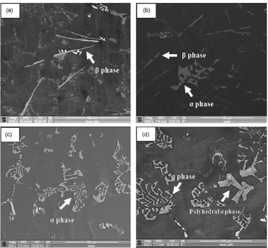
Fig. 2.17: SEM backscattered images showing the effect of different levels of Mn content on the formation of Fe-containing IMCs in an Al-Si-Cu based alloy. (a) 0.02 pct Mn, (b) 0.3 pct Mn, (c) 0.65 pct Mn and (d) 0.85 pct Mn [101].
Although the effects of Mn on the microstructure of Al-based alloys are well reported [54, 63, 65, 69, 74, 95, 98, 102-107], the amount of Mn needed to neutralize platelet-like β-Al5FeSi IMCs is not well established [2, 4]. When the Fe content exceeds 0.45 pct in permanent or sand mold castings, it is recommended that the Mn content should be almost half of the Fe content to replace the platelet β-Al5FeSi IMCs with Chinese-script α-Al15(Fe,Mn)3Si2 IMCs [2]. However, the formation of β-Al5FeSi IMCs
35
has not been completely eliminated even at a Mn:Fe ratio of 2:1 [107]. Mascre [31] proposed a neutralization formula for an Al-l3Si based alloy containing up to 1.3 pct Fe:
𝑀𝑛 = 2(𝐹𝑒 − 0.5) (2.1) where Mn is the elemental content required to replace β-Al5FeSi IMCs with α-Al15(Fe,Mn)3Si2 IMCs for a given Fe content. According to Shabestari and Gruzleski [108], the critical Mn:Fe ratio to replace β-Al5FeSi IMCs with α-Al15(Fe,Mn)3Si2 IMCs is 0.25. Cao and Campbell [109] observed the formation of Chinese-script α-Al15(Fe,Mn)3Si2 IMCs at a Mn:Fe ratio as low as 0.17 in an Al-11.5Si-0.4Mg based alloy, suggesting that this might be the minimum ratio necessary for α-Al15(Fe,Mn)3Si2 IMCs. Samuel et al. [63] reported that a Mn:Fe ratio of 0.7 was optimal in an Al-6.5Si-3.5Cu based alloy containing up to 1 pct Fe, leading to improved strength and ductility.
Transforming the β-Al5FeSi IMCs to α-Al15(Fe,Mn)3Si2 IMCs by Mn addition is greatly limited since a much coarser variation of the α-Al15(Fe,Mn)3Si2 IMC, commonly termed sludge, occurs at increased additions of Mn. Fig. 2.18 shows an example of sludge occurring in an Al-Si based alloy. Sludge IMCs constitute as hard spots significantly reducing the machinability of the alloy [110]. Sludge has an increased tendency to segregate due to its higher density compared to liquid Al and high melting point [100, 108, 111, 112]. Sludge is frequently seen in die-casting since the melts are often held at low temperatures and the alloys typically comprise of high Fe and Mn contents. Sludge is also common in sand castings since gravity segregation is favored by slow cooling.
36
Build-up of gravity segregating sludge IMCs damages furnace walls and eventually leads to a completely depleted furnace capacity.
Fig. 2.18: SEM image showing the occurrence of sludge α-Al15(Fe,Mn)3Si2 IMCs in an Al-11.5Si-0.4Mg based alloy [112].
Several empirical formulae have been derived to predict the formation of gravity segregating sludge α-Al15(Fe,Mn)3Si2 IMCs. The Iron Equivalent Value (IEV) is the most commonly accepted empirical formula and expressed as [113]:
𝐼𝑟𝑜𝑛 𝐸𝑞𝑢𝑖𝑣𝑎𝑙𝑒𝑛𝑡 𝑉𝑎𝑙𝑢𝑒 (𝐼𝐸𝑉) = 1𝐹𝑒 + 2𝑀𝑛 + 3𝐶𝑟 (2.2) where Fe, Mn and Cr are the amounts of the elements (all in wt pct) in the alloy. The IEV has been found to empirically correspond to a minimum allowable holding temperature, below which the formation of sludge occurs in Al-Si based alloys [113]. The critical temperature of some Al-Si based alloys can be predicted from the work in Refs. [100, 111, 113, 114]. For instance, an Al-5Si-3Cu alloy with a critical IEV of less than or equal to 1.97 should prevent sludge formation at casting temperatures above
37
650 °C [114]. Osame et al. [115] also formulated an empirical relationship describing the critical Fe and Mn contents for the formation of sludge IMCs in an Al-Si-Cu based alloy at a given holding temperature. However, only two holding temperatures were investigated and hence the sufficiency of the formula could be doubted.
A strong linear relationship between the IEV of an alloy and volume fraction of sludge has been reported [106, 116-118], indicating that the IEV may be used as a reliable predictor for the amount of sludge in Al-based alloys. For instance, Shabestari [106] developed an empirical linear equation given by:
𝑉𝑠𝑙𝑢𝑑𝑔𝑒 = 1.33 ∗ 𝐼𝐸𝑉 + 1.53 (2.3) where Vsludge is the volume fraction of sludge for a given IEV. The equation indicates that no sludge IMCs will appear in alloys with an IEV of less than 1.20. Nonetheless, it is important to note that the formation of sludge IMCs is also strongly dependent on the holding temperature and time [100, 106, 108, 111, 115] and presence of inclusions [60, 112, 119, 120].
To summarize, limiting the Fe content to <0.7 pct can mitigate the negative effects of Fe in Al-Si based alloys by preventing the formation of pre-eutectic platelet-like β-Al5FeSi IMCs. However, this critical value is difficult to meet in recycled materials. The other approach is to replace the platelet-like β-Al5FeSi IMCs with more globular-shaped α-Al15(Fe,Mn)3Si2 IMCs by Mn addition. However, the sole use of Mn to correct the effect of Fe will increase the amount of Fe-containing IMCs in recycled
38
material due to Mn accumulation. Therefore, it is desirable to find an alternative procedure to control the Fe-containing IMCs and thereby minimize the use of Mn for sustainable recycling.
2.8.2
Thermal Treatments
2.8.2.1
Cooling Rate
The amount, size, type and distribution of the Fe-containing IMCs depend on the cooling conditions. A strong linear relationship between the dendritic arm spacing (DAS) and average β-Al5FeSi IMC length has be

![Fig. 2.5: Al corner of the Al-Fe-Si diagram [27]: (a) liquidus and (b) phase distribution in the solid](https://thumb-us.123doks.com/thumbv2/123dok_us/75392.2508569/40.892.172.724.239.939/fig-al-corner-diagram-liquidus-phase-distribution-solid.webp)
![Fig. 2.7: Scanning electron microcopy (SEM) image showing a δ-Al 3 FeSi 2 IMC enveloped by a β-Al 5 FeSi IMC due to an incomplete peritectic transformation [48]](https://thumb-us.123doks.com/thumbv2/123dok_us/75392.2508569/45.892.267.624.105.392/scanning-electron-microcopy-showing-enveloped-incomplete-peritectic-transformation.webp)
![Fig. 2.12: Quantified β-Al 5 FeSi IMC nucleation rates in an Al-7.5Si-3.5Cu-0.6Fe alloy for different nucleation mechanisms [59]](https://thumb-us.123doks.com/thumbv2/123dok_us/75392.2508569/50.892.265.628.101.451/quantified-fesi-nucleation-rates-alloy-different-nucleation-mechanisms.webp)
![Fig. 2.13: AlP particles associated with a β-Al 5 FeSi IMC in an Al-6Si-3.5Cu based alloy [62]](https://thumb-us.123doks.com/thumbv2/123dok_us/75392.2508569/51.892.267.631.580.981/fig-alp-particles-associated-fesi-imc-based-alloy.webp)
![Fig. 2.19: The relationship between DAS and the length of β-Al 5 FeSi IMCs in an Al-7Si-0.3Mg based alloy [66]](https://thumb-us.123doks.com/thumbv2/123dok_us/75392.2508569/64.892.265.629.103.430/fig-relationship-das-length-fesi-imcs-based-alloy.webp)
![Fig. 2.20: Optical micrograph showing the microstructure of a rapidly solidified Al-20Si-5Fe-3Cu-1Mg alloy [124]](https://thumb-us.123doks.com/thumbv2/123dok_us/75392.2508569/65.892.266.624.101.372/fig-optical-micrograph-showing-microstructure-rapidly-solidified-alloy.webp)
![Fig. 2.22: The change in Fe-containing IMCs in an Al-20Si-2Fe based alloy with different USMT times: (a) 0 s, (b) 60 s, (c) 120 s, and (d) 180 s [8]](https://thumb-us.123doks.com/thumbv2/123dok_us/75392.2508569/72.892.172.724.375.788/change-containing-imcs-based-alloy-different-usmt-times.webp)

