11-1
© 2011 Schneider Electric All Rights Reserved
11
SWIT C HBOA RDS A N D SWITC HGEARTable of Contents
Section 11
Switchboards and Switchgear
Transparent Ready™ Equipment
Switchboards and switchgear with Powerlogic™ circuit monitors and Web-enabled ethernet communication devices are part of the Transparent Ready power equipment family from Schneider Electric.
When specified as Transparent Ready, the power equipment is provided with a factory- configured “plug and play” communications system that allows the authorized user access to equipment status and monitoring information using only a standard Web browser. Ask your local Schneider Electric representative for details about Transparent Ready power distribution equipment.
QED-2 Switchboard see page 11-2
Metalclad and HVL/cc Switchgear see pages11-8 and 11-16
Unit Substation see page 11-17
Model III Package Unit Substation see page 11-17
Power-Style™ Switchboards
QED-2 Switchboard (UL Listed) 11-2
QED-6 Switchboard (UL Listed) 11-3
Commercial Multi-Metering Switchboards 11-3
Speed-D™
Switchboards
Speed-D SB/SF Switchboards (UL Listed) 11-4, 11-5
Low Voltage Switchgear
Power-Zone™ 4 Low Voltage Switchgear with Masterpact™ Circuit Breakers
11-6
Micrologic™ Trip Units 11-6
Medium Voltage Switchgear
MiniBreak™ Compact Height Switches— 5.5 kV—200 A 11-7 HVL/cc Metal-Enclosed Load Interrupter Switchgear—Full Range 11-8 HVL/cc Switchgear—Quick Ship Program—5–15 kV, 600 A 11-9, 11-10 HVL Metal-Enclosed Load Interrupter Switchgear—Full Range 11-11 HVL Switchgear—Quick Ship Program— 5 kV–15 kV, 600 A
Features
11-11
HVL Switches for Power-Dry II ™, Power-Cast II ™, and Uni-Cast II ™ Transformer Connections
11-12, 11-13
Square D™ brand DIN/E Fuse Selection Tables—HVL 11-14
Fuse Selection Tables Boric Acid Fuses—HVL 11-14
DVCAS Switchgear for Wind Farm Applications 11-15
Masterclad™ Medium Voltage Metalclad™ Switchgear (UL Listed) 11-16
Arc Terminator™ Arc Extinguishing System 11-16
Unit Substations
Unit Substations 11-17
Power-Zone™ Model III Package Unit Substations 11-17
MV Controllers and Substation Circuit Breakers
Motorpact™ Medium Voltage Motor Controllers (UL Listed) 11-19 Vacuum Substation Circuit Breaker—Types FVR, EOX, and VOX
(Not UL Listed)
11-19
MV Overhead Distribution
Automatic Circuit Recloser 11-20
Load Break Switch/Sectionalizer 11-20
www.schneider-electric.us
11-2 © 2011 Schneider Electric
All Rights Reserved
11
SWI TCHB OARD S AND SWITCHGEARPower-Style™
Switchboards
QED-2 (UL Listed)
Classes 2741, 2742 / Refer to Catalog 2700CT1101 or Brochure 2700BR0202
Power-Style QED-2 Switchboards (UL Listed)
For solutions that bring people, products, and information together, Square D™ brand Power-Style QED-2 low voltage switchboards from Schneider Electric are built to last and feature design innovations that make these products easier to install and maintain. Supported by one of the largest distributor, sales, and service organizations in the industry, QED-2 switchboards are readily available to meet the needs of contractors, consultants, and end-users.
Q = Quality—Built to Last
As one of the most trusted names in electrical distribution, Square D™ brand QED-2 switchboards are designed with the highest standards of quality. From sturdy frames, securely fastened thread-forming screws, and standard bolted, base channels, users will see the difference during installation, operation, maintenance, and expansion projects. E = Efficient and Innovative Designs
In 2010, Schneider Electric launched QED-2, Series 2 switchboard designs. Series 2 designs represent the next generation of our QED-2 switchboard offering, with new features based on extensive customer feedback. From improved branch neutral and ground bar access, to enhanced instrument compartments, Series 2 designs provide easier access for performing equipment installation and maintenance procedures.
QED-2 switchboards feature Schneider Electric's unique I-Line™ plug-on connections in group-mounted construction. With the I-Line design, a screwdriver is the only tool required to firmly ratchet the line end of a molded-case circuit breaker directly onto the I-Line bus assembly. This plug-on design allows quick installation and mounting flexibility of circuit breakers up to 1200 A.
D = Delivery—Ready When You Are
To meet tight project schedules and budgets, our Square D™ brand QED-2 switchboard offering brings together standard designs for the most frequently requested ratings and options, providing immediate pricing for quick shipments from 11 to 30 business days.
Features
•
QED-2 Switchboards are designed, listed, and built to UL 891•
Switchboard ratings through 6000 A, 200 kA; higher amperages available•
Front accessible load connections•
Front and rear alignment standard•
Cable, busway, transformer, or remote QED switchboard incoming fed•
Hot or cold sequence utility metering•
Thermal-magnetic, PowerPact™ electronic, or Masterpact™ NW stored energy fixed or drawout circuit breakers used as mains and feeders•
Group-mounted circuit breaker and fusible switch mains and feeders•
Fixed-mounted fusible swThe itch mains and feeders•
Powerlogic customer metering, including option for custom communications capability and interwiring•
Networked communications capabilities provide direct access to energy management at main and feeder level•
Internally-mounted Surgelogic™ surge protective devices•
Quick Connect Generator option available•
Main devices in six sub-division or single main configurations•
Main and branch devices in single section configuration•
Multiple individual devices in single section configurations•
Custom engineering, including main-tie-mains, multiple sets of thru-bus, reduced heights, and engineered housesQED-2 Switchboard
www.schneider-electric.us
© 2011 Schneider Electric
All Rights Reserved 11-3
11
SWIT C HBOA RDS A N D SWITC HGEARPower-Style™
Switchboards
QED-6 (UL Listed); Commercial Multi-Metering (UL Listed)
Classes 2746, 2755, 2756 / Refer to Catalogs 2746CT0101, 2755CT9501, 2756CT9601
Power-Style QED-6 Switchboards (UL Listed)
Masterpact™ NW and NT, and PowerPact™ H, J, and D Circuit BreakersThe QED-6 switchboard is designed to provide excellent distribution, protection, and power quality management in commercial electrical equipment. The circuit protection components of the switchboard are the Masterpact NW circuit breakers in 800–6000 A frame sizes, Masterpact NT circuit breakers in 800–1200 A frame sizes, and
PowerPact H, J, and D circuit breakers in 15–600 A frame sizes. These circuit breakers deliver maximum system uptime, system selectivity, ease of maintenance, and reliable circuit protection.
QED-6 switchboard features include: Masterpact NW UL 489 Listed circuit breakers for main and feeder devices, Masterpact NT UL 489 Listed circuit breakers for feeder devices, PowerPact H, J, and D UL 489 Listed circuit breakers for feeder devices, and a wide range of designs and options. Highly flexible drawout/plug-in circuit breakers can meet a wide variety of power distribution requirements. Choices include plug-in or drawout construction in PowerPact H, J, and D circuit breakers, and optional prepared drawout or plug-in spaces that are equipped with all specified control functions. This capability allows quick additions for load upgrades.
•
QED-6 switchboards are designed, listed, and built to UL 891; Masterpact and PowerPact circuit breakers are designed, listed, and built to UL 489•
Circuit breakers are individually mounted, rear connected; Masterpact NW and NT circuit breakers are drawout; PowerPact H, J, and D breakers are plug-in as standard, drawout as an option•
Family of field installable and upgradeableMicrologic™ trip units with optional Powerlogic™ data communications features
•
Switchboard ratings up to 150 kA short-circuit current rating for services 1600–6000 A at 480 V and 100 kA at 600 V•
Up to (12) 250 A PowerPact H and J circuit breakers in a single 30-inch wide section•
Up to (8) 600 A frame PowerPact D or(8) 1200 A frame Masterpact NT circuit breakers in a single 30-inch wide section
•
Flexible branch circuit breaker locations: Masterpact NW and NT and PowerPact H, J, and D circuit breakers can be mixed in a single 30-inch wide section (15–2000 A)•
Compartmentalization: separate compartments for circuit breakers, bussing, and load cabling•
Available in 54-, 60-, 72-, and 80-inch deep construction•
Available in NEMA 3R outdoor walk-in enclosures•
Masterpact and PowerPact circuit breakers are field maintainableQED-6 switchboards are reliable power protection equipment when working with telecommunication facilities, e-business servers, or mainframes that perform critical business transactions. These types of facilities cannot afford downtime.
QED-6 rear-connected switchboards are designed as standalone switchboards or as an integral part of the low voltage equipment lineup in a user’s power unit substation.
Specify QED-6 Switchboards
When drawout construction is required for quick circuit breaker changeout; system requirements call for circuit breakers to close within five cycles; stored energy circuit breakers are required; front access to control wires is desired; ease of installation, maintenance, and upgrade of circuit breaker compartmentalization is required; system integrity and segregation of circuit breaker compartments from bus and cable compartments is required; equipment isolation is required.
Benefits/Values of Circuit Breaker Performance
Masterpact NW and NT circuit breakers are designed to provide maximum protection and reliable operation with a long service life. They exceed all UL 489 endurance testing requirements and are certified to a minimum of 10,000 operations through the 3000 A frame.
System Coordination
Short-time ratings are high, giving users excellent system coordination and selectivity with downstream breakers.
High Short-Circuit Current Ratings (SCCR)
Up to 200 k AIR at 240 V, 150 k AIR at 480 V, and 100 k AIR at 600 V, which allows customers to design systems with high fault current and paralleling schemes.
Arc Flash Limiting (LF) Feeder Breakers
High speed operation of Masterpact NW and NT circuit breakers (150 k AIR at 480 V) helps reduce arc flash incident energy (cal/cm2) on downstream equipment.
Ease of Installation and Maintenance
Thru-the-door construction, an easy to operate drawout mechanism, and front access to all control wiring make this equipment easy to install, maintain, and upgrade. Load connections in the cable compartment are easily accessible in the rear of the switchboard. Remote racking of the Masterpact NW circuit breaker is also available with the optional remote racking tool, which, if required, is field installable.
Ability to Upgrade
UL Listed, field-installable accessories include: motor operators, shunt trips, under voltage devices, trip units, and communication modules for trip units. Manually operated circuit breakers are field convertible to electrical operation.
Open Communication System
The Micrologic trip units in Masterpact NW and NT circuit breakers use the Modbus™protocol. This is a widely accepted protocol, which allows QED-6 to be integrated into new or many existing communication systems.
Adaptable
Drawout and bolt-in circuit breakers, front access control wiring, and expandable lineups are quickly adaptable to changing load and control requirements.
Expandable
Masterpact NW and NT circuit breakers have many control termination points, giving the equipment extensive flexibility and expandability for sophisticated control schemes.
Power-Style Commercial Multi-Metering
Switchboards (UL Listed)
•
Designed, built, and listed to UL 891•
Lever bypass and EUSERC non-lever bypass•
Hot or cold sequence metering—EUSERC, NEMA, LOCAL•
Front and rear alignment standard•
Switchboard ratings through 4000 A, 100 kA•
Meter sections in either three- or six-socket section configuration•
Tenant mains either circuit breaker or fusible•
60–200 A without lever bypass with self-contained meter sockets, 5- or 7-jaw, ring type and test block where required•
60–200 A lever bypass with self-contained meter sockets, 7-jaw, ringless•
Factory-installed devices with completely wired from meter socket to disconnect•
Provisions for adding future tenants available, as well as future sections•
Sections in either NEMA 1 or NEMA 3R construction•
For use on 120/240 V, 120/208 V, and 277/480 V systems•
Integrated, front-accessible wireway for top exiting load cables•
Customer access area for top exiting load cables QED-6 Switchboard (Class 2746) Table 11.1: Circuit Breaker Selection Rating (A)(Frame) Circuit Breakers
150–250 PowerPact H, J 400–600 PowerPact D 800–1200 Masterpact NT 800–6000 Masterpact NW EUSERC Lever Bypass Classes 2755, 2756
www.schneider-electric.us
11-4 © 2011 Schneider Electric
All Rights Reserved
11
SWI TCHB OARD S AND SWITCHGEARSpeed-D™ Switchboards
Class 2710 / Refer to Catalog 2700CT1101
Speed-D SB/SF Switchboards (UL Listed)
•
UL Listed•
Hot sequence utility compartment per EUSERC requirements•
Two types:— Utility–Service disconnect–distribution — Utility–Up to six service disconnects
•
Single service disconnect, either circuit breaker or fusible rated 400, 600, or 800 A with either type of distribution interiors, NQ up to 240 Vac, I-Line™ through 480 Vac•
Six service disconnects, group-mounted fusible, QMB/QMJ, 30–400 A; utility compartment—400, 600, and 800 A•
Meter doors can be 15 inches high with one meter socket and test block, or 30 inches high with two meter sockets and test block•
Meter sockets can be 6-, 8-, 13-, or 15-jaw meter sockets with test block, based on application•
Accessories include:— Underground pull sections with and without lug landing — Loadside wireway
— Bus links for donut-type current transformers — Double padlock hasp attachments
— Plug-on distribution panel — Subfeed circuit breakers
•
Full height add-on I-Line distribution section•
Stand-alone I-Line distribution sectionApplication
Suitable for use as service entrance equipment on ac systems. Sections contain metering compartment, barriers, main disconnects, distribution panel, neutral bus, and grounding provisions.
Metering
C/T compartment with two 15-inch blank meter doors. (Order doors with meter socket from Table 11.6 on page 11-5.) Incoming cable lugs are for top feed with one twin conductor 2 AWG–600 kcmil lug per phase and neutral, suitable for aluminum or copper cables. Optional single conductor lug is available. Refer to Table 11.7 on page 11-5.
Mains
Main circuit breaker types are either LH or MJ. Main fusible device is supplied with Class T fuses. Multiple main devices use plug-on fusible switches.
Branches
NQ distribution bus is rated 400 A and provides mounting space for QO™/QOB Type (150 A maximum) circuit breakers. Panel provides space for mounting 42 single pole circuit breakers. One or two individually mounted 225 A maximum circuit breakers can be added with bus connectors. (Order subfeed circuit breakers from
Table 11.8 on page 11-5.)
I-Line™ distribution bus is rated 400, 600, or 800 A and will accept 27 inches of I-Line circuit breakers on the left side with a maximum frame size of “J” . The right side will accept either a QO plug-on distribution panel (240 V only) or LA or LH I-Line circuit breaker.
Enclosure
Totally enclosed front accessible with ANSI 49 gray baked enamel finish. Dimensions are 90 in. (H) x 36 in. (W) x 14 in. (D) for indoor and 90 in. (H) x 36 in. (W) x 24.5 in. (D) for outdoor enclosures.
EUSERC Utility Metering, Main Disconnects and Distribution Panel (UL Listed)
EUSERC UCT, Single Main Circuit Breaker with
I-Line Distribution Panel
EUSERC UCT, Fusible Multiple Mains
Table 11.2: Single Main Circuit Breaker with Distribution (Series E4) Sy st em Service Voltage Ma ins R a tings (A ) Distrib ution Inte rior SCCR 24 0 V Max . SCCR 48 0 V Circuit Breaker Indoor Outdoor Catalog No. $ Price Catalog No. $ Price 1Ø3W 120/240 400 NQ 65 — SB124QS 7895.00 SB124QR10645.00 I-Line 65 — SB124IS 8700.00 SB124IR 11450.00 None 65 — SB124WS 6680.00 SB124WR 9430.00 600 I-LineNone 6565 —— SB126WSSB126IS 10975.008016.00 SB126WRSB126IR 13726.0010766.00 3Ø4Wa 208Y/120240/120 400 NQ 65 — SB324QS 8651.00 SB324QR11401.00 3Ø4Wa 208Y/120240/120 400 None 65 — SB324WS 7281.00 SB324WR10031.00 3Ø4Wa
208Y/120
400 I-Line 65 35 SB344IS 9673.00 SB344IR 12423.00 240/120 480Y/277 3Ø4Wa 208Y/120 400 None 65 35 SB344WS 7653.00 SB344WR10403.00 240/120 480Y/277 3Ø4Wa 208Y/120
600 I-Line 65 50 SB346IS 12820.00 SB346IR 15570.00 240/120 480Y/277 3Ø4Wa 208Y/120 600 None 65 65 SB346WS 9860.00 SB346WR13229.00 240/120 480Y/277 3Ø4Wa 208Y/120
800 I-Line 65 50 SB348IS 19569.00 SB348IR 22038.00 240/120 480Y/277 3Ø4Wa 208Y/120 800 None 65 65 SB348WS 18669.00 SB348WR21137.00 240/120 480Y/277
a Can be used on 3Ø3W Delta voltage systems (for example, 240 V Delta or 480 V Delta).
Table 11.3: Single Main Fusible Disconnect with Distribution (Series E4) Sy st em Service Voltage Ma ins Rat ings (A) D istrib ution In te ri o r SCCR 24 0 V SCCR 48 0 V Fusible Disconnect Indoor Outdoor Catalog No. $ Price Catalog No. $ Price 1Ø3W 120/240 400 NQ 65 — SF124QS 8150.00 SF124QR10900.00 I-Line 100 — SF124IS 8995.00 SF124IR 11705.00 None 200 — SF124WS 6935.00 SF124WR 9685.00 600 I-Line 100 — SF126IS 11906.00 SF126IR 14656.00 None 200 — SF126WS 8946.00 SF126WR11696.00 3Ø4Wb 208Y/120240/120 400 NQ 65 — SF324QS 8929.00 SF324QR11679.00 3Ø4Wb 208Y/120240/120 400 None 200 — SF324WS 7559.00 SF324WR10309.00 3Ø4Wb
208Y/120
400 I-Line 100 65 SF344IS 9682.00 SF344IR 12432.00 240/120 480Y/277 3Ø4Wb 208Y/120 400 None 200 200 SF344WS 7662.00 SF344WR10412.00 240/120 480Y/277 3Ø4Wb 208Y/120
600 I-Line 100 65 SF346IS 14453.00 SF346IR 17203.00 240/120 480Y/277 3Ø4Wb 208Y/120 600 None 200 200 SF346WS 11493.00 SF346WR14243.00 240/120 480Y/277 3Ø4Wb 208Y/120
800 I-Line 100 65 SF348IS 25401.00 SF348IR 28782.00 240/120 480Y/277 3Ø4Wb 208Y/120 800 None 200 200 SF348WS 24501.00 SF348WR27881.00 240/120 480Y/277
b Can be used on 3Ø3W Delta voltage systems (for example, 240 V Delta or 480 V Delta).
Table 11.4: Multiple Mains—Fusible (Series E4)c
System Service Voltage Mains Rating (A) 240 V or 480 V Max. d
Multiple Mains (6) Fusible
Indoor Outdoor Catalog No. $ Price Catalog No. $ Price 1Ø3W 120/240 400 200 SF124FS 5565.00 SF124FR 8478.00 1Ø3W 120/240 600 200 SF126FS 6678.00 SF126FR 8966.00 3Ø4We 208Y/120 400 200 SF344FS 7025.00 SF344FR 10050.00 240/120 408Y/277 3Ø4We 208Y/120 600 200 SF346FS 7319.00 SF346FR 10233.00 240/120 480Y/277 3Ø4We 208Y/120 800 200 SF348FS 8283.00 SF348FR 11199.00 240/120 480Y/277
c Multiple mains—provisions for mounting 30 inches of fusible devices. No more than six main devices permitted per NEC.
d QMB/QMJ fusible switches, maximum 400 A, SCCR based on Class J, R, or T fuses. QMB plug-in circuit breaker rating is equal to the lowest rating of the circuit breaker. e Can be used on 3Ø3W Delta voltage systems (for example, 240 V Delta or 480 V Delta).
PE1A Discount Schedule
www.schneider-electric.us
© 2011 Schneider Electric
All Rights Reserved 11-5
11
SWIT C HBOA RDS A N D SWITC HGEARSpeed-D™ Switchboards
Merchandised, Service Selection
Class 2710 / Refer to Catalog 2700CT1101
Ordering Information
1. Service section: Order service section from either Table 11.2 on page 11-4 (single main circuit breaker with distribution), Table 11.3 on page 11-4 (single main fusible with distribution), or Table 11.4 on page 11-4 (multiple mains fusible), as determined by mains rating, voltage, and system.
2. Meter doors: Order meter door from Table 11.6 (meter door selection) as determined by the height and utility metering requirements.
3. Accessories and subfeeds: Order as required from Table 11.7 (accessories) and/or Table 11.8 (subfeed circuit breakers).
4. Circuit breakers and switches: Order devices from pages listed below as determined by voltage, trip rating, AIR, and mounting space.
Multiple Mains and Branch Devices
•
QO, QOB, QO-VH, QOB-VH: pages 7-10 and 9-10•
I-Line: pages 9-24 to 9-30•
QMB Switches: page 9-35 Table 11.5: I-Line™ Distribution Section (Series E4)System Service Voltage Mains Ratings (A) Distribution Interior SCCR 240 V Max. SCCR 480 V Max. Distribution Type Indoor Outdoor Catalog No. $ Price Catalog No. $ Price 3Ø4W 208Y/120 240/120 480Y/277 800 I-Line 65 k 65 k
Add-on distribution section, must be connected to an SB UCT and main section without distribution panel, such as SB348WS. An I-Line plug-on subfeed lug kit must be ordered to terminate the distribution section.
SBAD800 10260.00 SBAD800R 13305.00 3Ø4W 208Y/120 240/120 480Y/277 800 I-Line 125 k 100 k
Stand-alone distribution section not connected to an SB section. A back-fed main circuit breaker or I-Line plug-on subfeed lug kit must be ordered to terminate the distribution section. (Non-ULSE)
SBSAD800 10620.00 SBSAD800R 13770.00
Table 11.6: Meter Door Selection
Meter Socket Jaws
15-inch High Door With One Meter Socket and Test Block
30-inch High Door With Two Meter Sockets and Test Blocks
Catalog No. $ Price Catalog No. $ Price
6a SBA15D6MS 923.00 — — 8 SBA15D8MS 984.00 — — 13 SBA15D13MS 1230.00 SBA30D13MS 2093.00 15 SBA15D15MS 1358.00 SBA30D15MS 2217.00 Blank SBA15DBC 495.00 — — b SBA15DMS 617.00 — —
a 6-jaw meter socket can also be used on 4- and 5-jaw applications. b Door with provisions for mounting meter socket.
Note: To order structure with meter door factory-installed, add door catalog number as suffix to structure (e.g. SF344IS-15D13MS).
Table 11.7: Accessories
Description Catalog No. $ Price
Indoor underground pull section (w/o lug landing)—26-in. (W)
Order separate SA8LL lug kit below if required. SA26PS 2217.00
Outdoor (3R) underground pull section (w/o lug landing)—26 in. (W) x 24.5 in. (D)
Order separate SA8LL lug landing kit below when required. SA26PSR 4559.00
Lug landing kit—800 A max. For terminating utility service cables in indoor or outdoor underground pull sections. SA8LLc 753.00
Single barrel lug kit —Kit provides single barrel lugs and pad in lieu of twin barrel lug provided with service section.
Mechanical lugs provided are sized to fit 1-3/0–750 kcmil cable. Two lugs per phase are supplied. SA7PL 395.00
Loadside wireway—11.5 in. (W) x 14 in. (D)—indoor only SA10LW 1052.00
Bus link kit—800 A max.—Order one kit per phase for 400, 600, and 800 A. SA10BL 246.00
Double padlock hasp attachment—For mounting two padlocks on door handle of rainproof enclosure. Padlocks not included. SS2PL 113.00
Plug-On Distribution Panel—mounts on right side of I-Line interior. Cannot be used with LA/LH branch circuit breaker. Panel rated 225 A for 240 V applications. For QO™ type plug-on circuit breakers only.
System Phase Pole
Spaces 1Ø AC 12 SS212AC 2339.00 3Ø ABC SS312 2957.00 3Ø AB SS212ABd 2339.00
c All EUSERC Utilities (except Arizona Public Service and Salt River Project) require a lug landing kit SA8LL. d To be used on 120/240 V, 3Ø4W delta applications.
Table 11.8: Subfeed Circuit Breakers (Series E4) e
Description Rating (A) 2-Polef $ Price 3-Pole $ Price
Catalog No. Catalog No.
Left Right Left Right
Subfeed Circuit Breaker Kit—
Price includes circuit breaker, connectors and mounting hardware. The complete kit, mounting hardware, circuit breaker and connectors will be shipped direct from plant. Delivery is stock to three days.
100 SASFBH100L( ) SASFBH100R( ) 1480.00 SASFBH100L SASFBH100R 1850.00
110 SASFBH110L( ) SASFBH110R( ) 1480.00 SASFBH110L SASFBH110R 1850.00
125 SASFBH125L( ) SASFBH125R( ) 1480.00 SASFBH125L SASFBH125R 1850.00
150 SASFBH150L( ) SASFBH150R( ) 1480.00 SASFBH150L SASFBH150R 1850.00
175 SASFBJ175L( ) SASFBJ175R( ) 1644.00 SASFBJ175L SASFBJ175R 2055.00
200 SASFBJ200L( ) SASFBJ200R( ) 1644.00 SASFBJ200L SASFBJ200R 2055.00
225 SASFBJ225L( ) SASFBJ225R( ) 1644.00 SASFBJ225L SASFBJ225R 2055.00
e Cannot use subfeed circuit breaker kit with multiple mains service section switchboards.
f Two pole circuit breaker catalog numbers are completed by adding required phase connection letters as suffix (for example, SASFBH100LAC).
www.schneider-electric.us
11-6 © 2011 Schneider Electric
All Rights Reserved
11
SWI TCHB OARD S AND SWITCHGEARLow Voltage Switchgear
Metal-Enclosed Drawout
Class 6037 / Refer to Catalog 6037CT9901
Power-Zone™ 4 Low Voltage Switchgear
with Masterpact™ Circuit Breakers
Square D™ brand Power-Zone™ 4 low voltage,
metal-enclosed, drawout switchgear is designed to provide superior electrical distribution, protection, and power quality management. The prime components of the switchgear are the Masterpact™ NW and NT ANSI rated circuit breaker. Power-Zone 4 switchgear is designed to maximize the functionality of the Masterpact circuit breakers, which, in turn, deliver maximum uptime, system selectivity, ease of maintenance, and reliable circuit protection. All of these features are packed into the smallest footprint available for low voltage drawout switchgear.
•
Power-Zone 4 is designed and built to ANSI® C37.20.1 and is Listed to UL 1558•
Masterpact NW and NT drawout low voltage power circuit breakers are designed and built to ANSI C37.13 and C37.16. Listed to UL 1066•
Short-circuit current rating up to 200 kA at 240 V and 480 V without fuses•
High short-time withstand ratings up to 100 kA for 1 second, minimum•
Arc flash limiting (L1F) Masterpact NW feeder breakers available in 800, 1600, and 2000 A ratings•
Family of field installable and upgradeableMicrologic™ trip units with optional Powerlogic™ data communications features
•
Power-Zone 4 switchgear can offer optional data communications capability•
Smallest equipment footprint available in this product class•
Front access to all control and communications wire connections•
Bolted copper bus provided as standard (up to 6000 A maximum)•
Large rear cable compartment pull area allowing maximum room for power cables•
Horizontal bus provision for future equipment expansion•
System designed for maximum uptime with low maintenance•
Modular circuit breaker designed for easy addition of control accessories•
Available in NEMA 3R outdoor walk-in enclosuresMasterpact NW circuit breakers are available in various levels of interrupting ratings from 42–200 kA at 480V and 130 kA at 600 V.
The Masterpact NT circuit breaker is available in an 800A frame size and 42 kA at 480 V interrupting rating. Up to 8 Masterpact NT circuit breakers can be mounted in a 30-inch wide section. (Not available for 600 V.)
Circuit breakers of like frame sizes and interrupting ratings are interchangeable.
Micrologic™ Trip Units
A modern family of field-installable trip units is available with Masterpact NW and NT circuit breakers. The circuit breaker overcurrent protection consists of a
microprocessor-based tripping device that requires no external power source. The complete tripping system has three main components: the air-core sensors, the trip device (with rating plug), and the trip actuator. The microprocessor-based trip unit uses true RMS current level sensing.
The Metering and Communications system is used in conjunction with Micrologic Type A, Type P, and Type H trip units (see Digest pages 7-47 and 7-48) for the Masterpact NW and NT circuit breakers. Modbus™ industry standard data communications allow this system to replace discrete meters, multiple transducers, analog wires, and analog-to-digital conversion equipment. Extensive information can be transmitted over a single communications cable to a Powerlogic system display, a personal computer, programmable logic controller, or other host system. Basic circuit information, such as amperes, can be monitored using Micrologic Type A trip unit. Circuit breaker remote operation is available using the Micrologic Type P and Type H trip units with Powerlogic functionality. In addition to its metering capabilities, the Micrologic trip unit system is available with optional status inputs and relay outputs for monitoring discrete contacts and remote control of devices by way of the data communications channel. Micrologic trip unit metering functions include:
•
Amperes and volts•
Frequency•
Power•
Power demand•
Energy•
Energy demand•
Power factor•
Power quality measurements•
Communications•
Waveform capture•
Data logging•
Programmable contacts•
Current unbalance•
Over/under voltage•
Over/under frequency•
Voltage unbalance•
Phase sequence•
Reverse power•
Long time imaging•
Contact wear indicator•
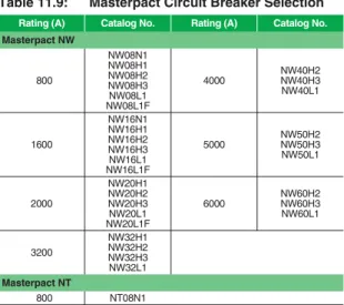
Masterpact circuit breaker maintenance informationTable 11.9: Masterpact Circuit Breaker Selection
Rating (A) Catalog No. Rating (A) Catalog No.
Masterpact NW 800 NW08N1 NW08H1 NW08H2 NW08H3 NW08L1 NW08L1F 4000 NW40H2 NW40H3 NW40L1 1600 NW16N1 NW16H1 NW16H2 NW16H3 NW16L1 NW16L1F 5000 NW50H2 NW50H3 NW50L1 2000 NW20H1 NW20H2 NW20H3 NW20L1 NW20L1F 6000 NW60H2 NW60H3 NW60L1 3200 NW32H1 NW32H2 NW32H3 NW32L1 Masterpact NT 800 NT08N1 Power-Zone 4 Low Voltage Switchgear (Class 6037)
www.schneider-electric.us
© 2011 Schneider Electric
All Rights Reserved 11-7
11
SWIT C HBOA RDS A N D SWITC HGEARMedium Voltage
Switchgear
Metal-Enclosed—MiniBreak™
Class 6042 / Refer to Brochure 6042BR9401
MiniBreak™ Compact Height Switches—
5.5 kV, 200 A
The Square D™ brand MiniBreak compact height switch enclosure is only 66-inches high and contains a single 3-pole load interrupter switch, rated 5.5 kV and 200 A. Enclosures are free-standing and suitable for both indoor (NEMA 1) and outdoor (NEMA 3R) applications. These switches are available unfused or with provisions for Square D™ brand current-limiting fuses rated from 10E A to 200E A. Factory-installed accessories include an auxiliary switch, strip heaters, and provisions for a “lock open” only key interlock. The door is mechanically interlocked with the switch operating handle. Set screw cable lugs for #14 solid—2/0 stranded aluminum or copper cable are provided for two line and one load connections. Fuses are not furnished with this equipment. For fuse information and pricing, see Table 11.12. The Fused switches and many of the fuses listed in Table 11.12 are available from stock.
NOTE:1200 hp maximum.
Ordering Information
1. Select switch catalog number based on fused or unfused.
2. Select catalog numbers for modifications from Factory Modifications table.
3. If fused, select 5 kV, 200 A maximum current-limiting fuse from table below.
4. Price switch and fuses separately. Switches are furnished with provisions only for fuses. 5. Weight 450 lbs (204 kg).
Pricing Example
Price one (1), 5 kV, 200 A switch with 65E current-limiting fuses. Provide one auxiliary switch with 1-N.O. and 1-N.C. contact and with provision for installing a “lock open” key interlock on the switch operating mechanism.
Table 11.10: Ratings
Max. design voltage (kV) 5.5
BIL (kV) 60
Frequency (Hz) 60
Continuous amperes 200
Interrupting amperes 200
Momentary (amperes asymmetrical) 20,000
Fault close (amperes asymmetrical) 20,000
Capacitor switching (kVAR) None
Short time, 2 seconds (amperes symmetrical) 12,500
Low frequency withstand (kV) 19
Fuse integrated (symmetrical) 63,000
Table 11.11: 5 kV—200 A Switch
Type Switch
Catalog No. $ Price
Unfused HVMB305200U 10274.00
Fused HVMB305200 11844.00
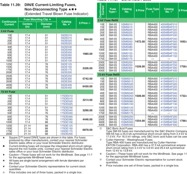
Table 11.12: Current-Limiting Fuses, Non-Disconnect Type (Extended Travel Blown Fuse Indicator)
Continuous Current
Fuse Mounting Clip
Catalog Numbera $ Priceb
Size Centers 5 kV Fuse 10E D 12” 5GS010 954.00 15E 5GS015 20E 5GS020 25E 5GS025 30E D 12” 5GS030 1980.00 40E 5GS040 50E 5GS050 65E 5GS065 80E 5GS080 100E 5GS100 125E D 12” 5GS125 3326.00 150E 5GS150 175E 5GS175 200E 5GS200
a Contact your Schneider Electric representative for current stock quantities.
b Price includes one set of three fuses, packed in a single box.
MiniBreak™ Switch Enclosure with Door
(Class 6042)
MiniBreak Switch Interior Showing Fuses
(Class 6042)
Listed Metal-enclosed Interrupter Switchgear
Table 11.13: Factory Modifications
Catalog No. Description $ Price
HVMX1 Auxiliary switch, 1-N.O. and 1-N.C. contacts 152.00 HVMK1 Provisions for lock open only key interlock (does not
include the key cylinder—order separately) 341.00
HVMH1 Strip heater 100 W @ 120 V 1150.00
HVMH2 Strip heater with thermostat 100 W @ 120 V 1772.00 HVMSA3 Distribution class surge arrester (set of three arresters) 3 kV, 2.55 MCOVc 1618.00 HVMSA6 Distribution class surge arrester
(set of three arresters) 6 kV, 5.10 MCOVc 1926.00 c Arresters are line side connected.
Order: Catalog No. $ Price
Switch with enclosure HVMB305200 11844.00
Auxiliary switch HVMX1 152.00
Key interlock adapter HVMK1 340.00
Fuses (set of three, from page 11-14) 5GS065 1980.00 Total Price 14316.00 25.15 639 25.20 640 15.35 390 47.52 1207 47.52 1207 29.00 737 25.20 640 66.00 1677 25.15 639 23.78 604 18.38 467 2.70 69 2.20 56 20.75 527 2.20 56
Front view Section view (unfused)
Section view (fused) Top view selected area recommended (bottom conduit entrance)
www.schneider-electric.us
11-8 © 2011 Schneider Electric
All Rights Reserved
11
SWI TCHB OARD S AND SWITCHGEARMedium Voltage
Switchgear
Metal-Enclosed —HVL/cc™
Class 6045 / Refer to Product Data 6040PD9601 or Handout 6040HO9501
HVL/cc Metal-Enclosed Load Interrupter
Switchgear—Full Range
Square D™ brand HVL/cc metal-enclosed load interrupter switchgear provides switching, metering, and interrupting capabilities for medium voltage electrical power
distribution systems and is designed and tested per applicable ANSI/IEEE and NEMA standards.
Made up of modular units, the HVL/cc is easy to expand. Two main bus positions allow future extensions and connections to existing equipment.
HVL/cc switchgear is available in either single or multiple bay units. The design is compact, with front accessibility. The HVL/cc switch can be equipped with either an over-toggle mechanism (OTM), which is standard, or an optional stored energy mechanism (SEM). An option with both mechanisms is the Fuselogic™ system. The Fuselogic system offers fuse tripping (with SEM) to provide protection against single phasing loads when a fuse has blown. It also has a mechanical interlock to prevent inadvertent switching until fuses have been installed or blown fuses have been replaced.
The HVL/cc enclosure is designed for front access only and can be positioned against walls, in small rooms or in pre-fabricated buildings. The small footprint can result in considerable cost savings from the reduction of building or room sizes.
Switch Standard Features
•
Switch Positions: Closed, open, and internally grounded (optional) (connects switch contacts to ground)•
Enclosure: Epoxy•
Medium: Sulphur hexalfluoride•
Maintenance: Maintenance free sealed for life•
Pressure:— 5.8 PSI (≤ 17.5 kV) — 22 PSI (25.8–38 kV)
•
View ports to show switch blade positionOptions
•
Internal ground switch: Has full fault making capability•
Fuselogic™ system•
Infrared viewing windows•
Class I, Division 2•
Fast auto transfers•
Duplex configurations•
Protective relaying•
Powerlogic™ metering•
20-inch or 29.5-inch wide enclosuresFuselogic™
Fuselogic is a protection system that provides the ultimate in medium voltage fuse protection. This patented system utilizes Square D™ brand current-limiting fuses with mechanical sensors that function without any auxiliary power requirements. Several combinations of Fuselogic functions can be combined to provide simple blown fuse indication contacts with mechanical lockout to anti-single phasing protection. Anti-single phasing requires the optional stored energy mechanism (SEM). Fuselogic is available on both HVL/cc and HVL switches.
Switchgear Standard Features
•
Compartments: Switch, bus, fuse/cable, mechanism, and optional low voltage/control•
11 gauge steel enclosure•
Epoxy insulators•
Fuse/cable access panel interlocked with switch•
Front access only•
Animated mechanism mimic bus•
Padlocking open or closed provision•
Top or bottom cable entry•
UL/CUL Listed•
Live line indicators on all incoming switch bays and outgoing feeder circuits•
Cable lugs included for one cable per phase•
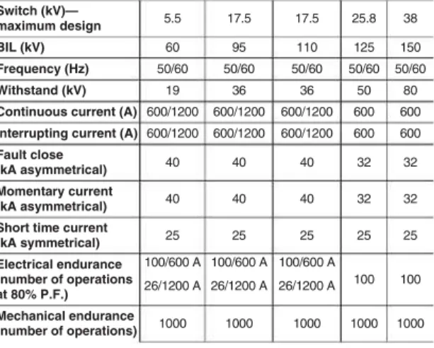
Tin plated copper bus for lineupsTable 11.14: HVL/cc Load Interrupter Switches— Full Range 600/1200 A Ratings
Switch (kV)—
maximum design 5.5 17.5 17.5 25.8 38
BIL (kV) 60 95 110 125 150
Frequency (Hz) 50/60 50/60 50/60 50/60 50/60
Withstand (kV) 19 36 36 50 80
Continuous current (A) 600/1200 600/1200 600/1200 600 600 Interrupting current (A) 600/1200 600/1200 600/1200 600 600 Fault close
(kA asymmetrical) 40 40 40 32 32
Momentary current
(kA asymmetrical) 40 40 40 32 32
Short time current
(kA symmetrical) 25 25 25 25 25 Electrical endurance (number of operations at 80% P.F.) 100/600 A 100/600 A 100/600 A 100 100 26/1200 A 26/1200 A 26/1200 A Mechanical endurance (number of operations) 1000 1000 1000 1000 1000 37.25 946 Optional low voltage compartment Mechanism compartment Fuse/cable access panel Front Switch with enclosure Main bus compartment Fuse cable compartment Right Side View 14.75 375 90.00 2286 37.25 946 W Plan View Front View Open Position To Ground Bus Closed Position To Ground Bus Grounded Position To Ground Bus
Switch Contact Positions
Table 11.15: Surge Arresters
System L-L Voltage kV Arrester MCOV-kV
Nominal Maximum Effectively Grounded Neutral Circuits Impedance Grounded and Ungrounded Circuits 2.4 4.16 4.8 6.9 12.0 2.54 4.4 5.08 7.26 12.7 — 2.55 — — 7.65 2.55 5.1 5.1 7.65 12.70 12.47 13.2 13.8 13.2 13.97 14.52 7.65 8.4 8.4 12.70 — — Listed Metal-enclosed Interrupter Switchgear
www.schneider-electric.us
© 2011 Schneider Electric
All Rights Reserved 11-9
11
SWIT C HBOA RDS A N D SWITC HGEARMedium Voltage
Switchgear
Metal-Enclosed —HVL/cc™
Class 6045 / Refer to Catalog 6045CT9801
HVL/cc Switchgear—Quick Ship Program—
5–15 kV, 600 A
The HVL/cc quick ship program provides basic fused and unfused load interrupter switch configurations for standalone or transformer primary applications. The Quick Ship program offers faster delivery, but with fewer options. Three-pole, 600 A individual HVL/cc switches are available in free-standing indoor (NEMA 1) enclosures.These switches are available unfused or with provisions for Square D™ brand current-limiting DIN/E fuses. Factory optional accessories include auxiliary bays, main bus, auxiliary switches, extra cable terminating lugs, and distribution class surge arresters. The fuse access panel is mechanically interlocked with the switch mechanism. Key interlocks are not an available option with Digest-listed HVL/cc switches. (1) Set screw type lugs for (2) #2–350 kcmil copper or aluminum cables are provided for line and load connections. Fuses are not furnished with this equipment. For fuse information and pricing refer to page 11-10.
Provisions for Future Expansion
All “single” HVL/cc switches have provisions for future expansion on either side.
Order main bus kits for copper 600 A bus. Include sketch for factory-assembled parts or lineups.
600 A Single Switch Unfused
Manual over-toggle mechanism, no grounding switch Includes (1) set screw for (2) #2–350 kcmil Cu or Al conductors per phase
Application A = Top entry (incoming—cable or main bus), bottom exit (load—cable or main bus)
Application B = Bottom entry (incoming—cable or main bus), top exit (load—cable or main bus)
600 A Single Switch Fused
(Provisions only for Square D™ brand current-limiting DIN/E fuses—order fuses separately)
Manual over-toggle mechanism, no grounding switch Includes (1) set screw lug for (2) #2–350 kcmil Cu or Al conductor per phase
Application A = Top entry (incoming—cable or main bus), bottom exit (load—cable or main bus)
Application B = Bottom entry (incoming—cable or main bus), top exit (load—cable or main bus)
600 A Incoming Line Auxiliary Bay
For top incoming cable to application A (bottom cable exit) switch(es), order 600 A tin plated Cu main bus to adjacent section from bus table. Includes (1) set screw lug for (2) #2–350 kcmil Cu or Al conductor per phase.
For bottom incoming cable to application B (top cable exit) switch(es), order 600 A tin plated Cu main bus to adjacent section from main bus kits table. Includes (1) set screw lug for (2) #2–350 kcmil Cu or Al conductor per phase.
600 A Tin Plated Copper Main Bus Kits
Ratings
HVL/cc Switch with manually operated type OTM mechanism in cubicle enclosure (does not include internal ground switch). Ratings are based on an X/R ratio of 1.6.
Factory Modifications
Distribution Class Surge Arresters
(One Set of Three) Switch Load Side Connected or Incoming Line Bay)
Table 11.16: Unfused Switch Selection
Catalog No. kV Rating Fuse Range Application Width $ Price in mm HVLCCA14305N 4.76 — A 14.75 375 17500.00 HVLCCA20305N 4.76 — A 20.00 508 18024.00 HVLCCA14315N 15 — A 14.75 375 19244.00 HVLCCA20315N 15 — A 20.00 508 19770.00 HVLCCB14305N 4.76 — B 14.75 375 17500.00 HVLCCB20305N 4.76 — B 20.00 508 18024.00 HVLCCB14315N 15 — B 14.75 375 19244.00 HVLCCB20315N 15 — B 20.00 508 19770.00
Table 11.17: Fused Switch Selection
Catalog No. kV Rating Fuse Range Application Width $ Price in mm HVLCCA14305D 4.76 10–450E A 14.75 375 19392.00 HVLCCA20305D 4.76 10–450E A 20.00 508 19916.00 HVLCCA14315D 15 10–200E A 14.75 375 19858.00 HVLCCA20315D 15 10–200E A 20.00 508 20382.00 HVLCCB14305D 4.76 10–450E B 14.75 375 19392.00 HVLCCB20305D 4.76 10–450E B 20.00 508 19916.00 HVLCCB14315D 15 10–200E B 14.75 375 19858.00 HVLCCB20315D 15 10–200E B 20.00 508 20382.00 90.00 2286 14.75 375 37.25 946 M M 450E
NOTE: Cable entry and
exit must be opposite to maintain the minimum sections shown.
5 kV Indoor N1 Top Cable In/Bottom Cable
Out Switch in Position A
90.00 2286 14.75 375 37.25 946 M M 450E Mechanical interlock between switch and fuse access panel.
5 kV Indoor N1 Top Cable In/Bottom Cable
Out Switch in Position B
NOTE: Mechanical
interlock is standard on switches.
Table 11.18: Bays for Top Entry/Exit Cables
Catalog No. kV Rating Fuse Range Application Width $ Price in mm HVLCCA14A 4.76/15 — A 14.75 375 1968.00 HVLCCA20A 4.76/15 — A 20.00 508 2492.00
Table 11.19: Bays for Bottom Entry/Exit Cables
Catalog No. kV Rating Fuse Range Application Width $ Price in mm HVLCCB14A 4.76/15 — B 14.75 375 1968.00 HVLCCB20A 4.76/15 — B 20.00 508 2492.00
Table 11.20: Bus Kits
Catalog No. Left (Fr om) Appli cation Width Right (T o) Appli cation Width $ Price in mm in mm HVLCCMBA14A14 A 14.75 375 A 14.75 375 882.00 HVLCCMBA14A20 A 14.75 375 A 20.00 508 946.00 HVLCCMBA20A14 A 20.00 508 A 14.75 375 946.00 HVLCCMBA20A20 A 20.00 508 A 20.00 508 1008.00 HVLCCMBB14B14 B 14.75 375 B 14.75 375 882.00 HVLCCMBB14B20 B 14.75 375 B 20.00 508 946.00 HVLCCMBB20B14 B 20.00 508 B 14.75 375 946.00 HVLCCMBB20B20 B 20.00 508 B 20.00 508 1008.00
Table 11.21: HVL/cc Switch Ratings
Switch (kV)—maximum design 5.5 17.5
BIL (kV) 60 95
Frequency (Hertz) 50/60 50/60
Withstand (kV) 19 36
Continuous current (amperes) 600 600
Interrupting current (amperes) 600 600
Fault close (amperes asymmetrical) 40,000 40,000
Integrated switch and fuse rating (amperes 65,000 65,000
Momentary current (amperes asymmetrical) 40,000 40,000
Short time current, 2 seconds (amperes symmetrical) 25,000 25,000
Operations at Full Load 100 100
Mechanical Endurance (number of operations) 1000 1000
a 50,000 for 630 A fuse.
Table 11.22: Factory Modifications
Catalog No. Description $ Price
HVLCC-X3 Auxiliary switch 2 N.O.–2 N.C. contact 762.00
Table 11.23: Surge Arresters
Catalog
No. kV Rating
Section Width
Minimum Required $ Price
in mm HVLCCDSA3 3 kV, 2.55 kV MCOV 14.75 375 1618.00 HVLCCDSA6 6 kV, 5.10 kV MCOV 14.75 375 1926.00 HVLCCDSA9 9 kV, 7.65 kV MCOV 14.75 375 2248.00 HVLCCDSA10 10 kV, 8.40 kV MCOV 14.75 375 2446.00 HVLCCDSA12 12 kV, 10.20 kV MCOV 14.75 375 2836.00 HVLCCDSA15 15 kV, 12.70 kV MVOV 20.00 508 3424.00 HVLCCDSA18 18 kV, 15.3 kV MCOV 20.00 508 3948.00 Listed Metal-enclosed Interrupter Switchgear
www.schneider-electric.us
11-10 © 2011 Schneider Electric
All Rights Reserved
11
SWI TCHB OARD S AND SWITCHGEARMedium Voltage
Switchgear
Metal-Enclosed—HVL/cc™
Class 6045 / Refer to Catalog 6045CT9801 600 A “Single” HVL/cc Switch with PROVISIONS ONLY
for Square D™ brand Current-Limiting,
Non-Disconnect Type Fuses for Cable Connection to Power-Dry™, Power-Cast™, and Uni-Cast™
Transformers
(FLC = 300 A MAXIMUM)
RH—Transformer on right, LH—Transformer on Left Application A = Top Entry (Incoming Cables) Application B = Bottom Entry (Incoming Cables)
NOTE:Switches with transformer connections are painted ANSI 49. Standalone switches are painted ANSI 61. Transformer connections in HVL/cc switches are based on standard Square D™ brand transformer connections. If these switches are used to connect to other manufacturers' transformers, then connections must match standard Square D™ brand transformer connections. (Cable connections are furnished with the transformer.)
General Purpose E-Rated Current-Limiting Fuses:Type DIN/E for HVL/cc Switches
Integrated rating for 600 A HVL/cc switches with Square D™ brand DIN/E fuses listed below is 65 kA rms symmetrical amperes. (50 kA rms for 630 A fuse.) Current-limiting fuses increase the integrated short-circuit current rating because of their energy-limiting capabilities. To increase the short-circuit current rating of the entire lineup of switchgear, current-limiting fuses must be used in the entrance sections.
600 A “Duplex” HVL/cc Switch with PROVISIONS ONLY for Square D™ brand Current-Limiting, Non-Disconnect Type Fuses for Cable Connection to Power-Dry, Power-Cast, and Uni-Cast Transformers
(FLC = 300 A MAXIMUM) RH—Transformer on Right,
LH—Transformer on Left Includes Mechanical Interlock to Prevent Paralleling of Sources
Application A = Top Entry (Incoming Cables) Application B = Bottom Entry (Incoming Cables)
Ordering Information
1. Select switch catalog number based on fused or unfused and cable entry locations (top or bottom) from Table 11.16 or Table 11.17 on page 9.
2. Select incoming line auxiliary bay from Table 11.18 or Table 11.19 on page 9, if required.
3. Select main bus from Table 11.20 on page 9, if required.
4. Select catalog numbers for factory modifications from Table 11.22 on page 9, if required.
5. If fused, select DIN/E fuses from Table 11.25.
Pricing Example
Order indoor 600 A, 5 kV, HVL/cc switch with bottom incoming and bottom outgoing cables (1) #2 AWG per phase, (1) set 200E fuses, and (1) set 6 kV surge arresters. Table 11.24: 600 A “Single” HVL/cc Switch Selection
Catalog No. kV Rating Fuse Range Applic ation Width RH / LH $ Price in mm HVLCCA14405DGR 4.76 10–450E A 14.75 375 RH 20134.00 HVLCCA20405DGR 4.76 10–450E A 20.00 508 RH 20660.00 HVLCCA14405DGL 4.76 10–450E A 14.75 375 LH 20134.00 HVLCCA20405DGL 4.76 10–450E A 20.00 508 LH 20660.00 HVLCCA14415DGR 15 10–200E A 14.75 375 RH 20614.00 HVLCCA20415DGR 15 10–200E A 20.00 508 RH 21138.00 HVLCCA14415DGL 15 10–200E A 14.75 375 LH 20614.00 HVLCCA20415DGL 15 10–200E A 20.00 508 LH 21138.00 HVLCCB14405DGR 4.76 10–450E B 14.75 375 RH 20134.00 HVLCCB20405DGR 4.76 10–450E B 20.00 508 RH 20660.00 HVLCCB14405DGL 4.76 10–450E B 14.75 375 LH 20134.00 HVLCCB20405DGL 4.76 10–450E B 20.00 508 LH 20660.00 HVLCCB14415DGR 15 10–200E B 14.75 375 RH 20614.00 HVLCCB20415DGR 15 10–200E B 20.00 508 RH 21138.00 HVLCCB14415DGL 15 10–200E B 14.75 375 LH 20614.00 HVLCCB20415DGL 15 10–200E B 20.00 508 LH 21138.00
Table 11.25: Fuse Selection
Catalog No. kV Rating Fuse Rating Set of Fuses a Fuse Size
Section
Width Required $ Price
in mm
55DE010 5.5 10E 1 Actual 14.75 375 954.00
55DE015 5.5 15E 1 Actual 14.75 375 954.00
55DE020 5.5 20E 1 Actual 14.75 375 954.00
55DE025 5.5 25E 1 Actual 14.75 375 954.00
55DE030 5.5 30E 1 Actual 14.75 375 1980.00
55DE040 5.5 40E 1 Actual 14.75 375 1980.00
55DE050 5.5 50E 1 Actual 14.75 375 1980.00
55DE065 5.5 65E 1 Actual 14.75 375 1980.00
55DE080 5.5 80E 1 Actual 14.75 375 1980.00
55DE100 5.5 100E 1 Actual 14.75 375 3326.00
55DE125 5.5 125E 1 Actual 14.75 375 3326.00
55DE150 5.5 150E 1 Actual 14.75 375 3326.00
55DE175 5.5 175E 1 Actual 14.75 375 3326.00
55DE200 5.5 200E 1 Actual 14.75 375 3326.00
55DE250 5.5 250E 1 Actual 14.75 375 5742.00
55DE300 5.5 300E 1 Actual 14.75 375 5742.00
55DE350 5.5 350E 1 Actual 14.75 375 5742.00
55DE400 5.5 400E 1 Actual 14.75 375 6430.00
55DE450 5.5 450E 1 Actual 14.75 375 6430.00
175DE010 15.5 10E 1 Actual 14.75 375 3214.00
175DE015 15.5 15E 1 Actual 14.75 375 3214.00
175DE020 15.5 20E 1 Actual 14.75 375 3214.00
175DE025 15.5 25E 1 Actual 14.75 375 3214.00
175DE030 15.5 30E 1 Actual 14.75 375 3290.00
175DE040 15.5 40E 1 Actual 14.75 375 3290.00
175DE050 15.5 50E 1 Actual 14.75 375 3290.00
175DE065 15.5 65E 1 Actual 14.75 375 4446.00
175DE080 15.5 80E 1 Actual 14.75 375 4446.00
175DE100 15.5 100E 1 Actual 14.75 375 4446.00 175DE125 15.5 125E 1 Actual 14.75 375 6878.00 175DE150 15.5 150E 1 Actual 14.75 375 6878.00 155DE175 15.5 175E 1 Actual 14.75 375 6878.00 155DE200 15.5 200E 1 Actual 14.75 375 6878.00 a Each (1) set of fuses contains three fuses. (E.g., (2) sets of fuses yield
a total of six fuses.)
90.00 2286 14.75 375 14.75 375 37.25 946 M M 200E 600A tin plated copper bus Listed Metal-enclosed Interrupter Switchgear
Table 11.26: 600 A “Duplex” HVL/cc Switch Selection Catalog No. kV Rating Fuse Range Width RH / LH $ Price Applica tion in mm HVLCCA14505DGR 4.76 10–450E A 14.75 375 RH 54174.00 HVLCCA20505DGR 4.76 10–450E A 20.00 508 RH 56068.00 HVLCCA14505DGL 4.76 10–450E A 14.75 375 LH 54174.00 HVLCCA20505DGL 4.76 10–450E A 20.00 508 LH 56068.00 HVLCCA14515DGR 15 10–200E A 14.75 375 RH 57428.00 HVLCCA20515DGR 15 10–200E A 20.00 508 RH 59322.00 HVLCCA14515DGL 15 10–200E A 14.75 375 LH 57428.00 HVLCCA20515DGL 15 10–200E A 20.00 508 LH 59322.00 HVLCCB14505DGR 4.76 10–450E B 14.75 375 RH 54174.00 HVLCCB20505DGR 4.76 10–450E B 20.00 508 RH 56068.00 HVLCCB14505DGL 4.76 10–450E B 14.75 375 LH 54174.00 HVLCCB20505DGL 4.76 10–450E B 20.00 508 LH 56068.00 HVLCCB14515DGR 15 10–200E B 14.75 375 RH 57428.00 HVLCCB20515DGR 15 10–200E B 20.00 508 RH 59322.00 HVLCCB14515DGL 15 10–200E B 14.75 375 LH 57428.00 HVLCCB20515DGL 15 10–200E B 20.00 508 LH 59322.00
Order: Catalog. No. $ Price
Switch w/fuse provisions and
bottom exit load cables HVLCCA14305D 19392.00 600 incoming line auxiliary bay
(Application A—bottom entry) HVLCCA14A 1968.00 Main Bus
(Application A—14 in. to Application A–14 in.) HVLCCMBA14A14 882.00
6 kV LAs HVLCCDSA6 1926.00
Set 200E fuses 55DE200 3326.00
Total Price 13747.00
PE5A Discount Schedule
www.schneider-electric.us
© 2011 Schneider Electric
All Rights Reserved 11-11
11
SWIT C HBOA RDS A N D SWITC HGEARMedium Voltage
Switchgear
Metal-Enclosed—HVL
Class 6040 / Refer to Catalog 6040CT9201 or Handout 6040HO9501
HVL Metal-Enclosed Load Interrupter
Switchgear—Full Range
HVL™ 5–38 kV Load Interrupter is the most popular ANSI-rated switchgear in its class in America. Among medium voltage interrupter switchgear, both the switch and the enclosure stand as industry benchmarks in the areas of design, manufacturing, and performance. Load interrupter switchgear must perform a number of critical functions in a unit substation - protecting equipment and disconnecting faulted lines and transformers. Designed and tested to the latest applicable standards, HVL has been engineered to provide superior protection for your distribution system. HVL switchgear is available for various applications and configurations, including:
•
Individual service entrance bays•
Multiple-bay lineups incorporating HVL loadinterrupters and optional Visi/Vac™ circuit interrupters
•
Substation primariesSquare D™ brand metal-enclosed switchgear has become an industry standard for its better system performance, lower maintenance cost, easier system expansion, and reduced system expense.
A full range of ratings and options are available but not listed in this publication. Contact your nearest Schneider Electric sales office or your local Schneider Electric distributor.
Standard Features
•
11 gauge steel enclosure•
Direct drive mechanism•
Permanently attached operating handle•
Visible isolation viewing window•
Mechanical interlocked fuse access door•
Provision for padlock and key interlock•
Highly flexible design•
ANSI 61 paintOptions
•
Outdoor construction•
Square D™ brand DIN-stylecurrent-limiting fuses•
Boric acid fuses•
Silver or tin plated copper bus•
600, 1200, or 2000 A main bus•
Heat shrinkinsulated bus•
Motor operator•
Shunt trip•
Fuselogic™ tripping system•
Automatic load transfer schemes•
Roof bushings•
Key interlocks•
Surge arresters•
Utility metering bays•
Line selector switch•
Duplex switch•
Transformer connections•
Infrared windows for thermal scanning of connectionsFuselogic™
Fuselogic is a protection system that provides the ultimate in medium voltage fuse protection. This patented system utilizes the Square D™ brand current-limiting fuses with mechanical sensors that function without any auxiliary power requirements. Several combinations of Fuselogic functions can be combined to provide simple blown fuse indication contacts with mechanical lockout to anti-single phasing protection. Anti-single phasing requires the optional stored energy mechanism (SEM). Fuselogic is available on both HVL/cc™ and HVL switches.
HVL Switchgear—Quick Ship Program—
5 kV–15 kV, 600 A Features
The HVL quick ship program provides basic fused and unfused load interrupter switch configurations for stand-alone or transformer primary applications. The Quick Ship program offers faster delivery, but with fewer options.
Three-pole, 600 A individual HVL switches are available in free-standing indoor (NEMA 1) or outdoor (NEMA 3R) enclosures. The switches used in these enclosures are UL Recognized and are listed under Category WIQG2 in File E140591(M). These switches are available unfused or with provisions for 3-inch diameter Square D™ brand current-limiting fuses or for boric acid fuses. Factory optional accessories include auxiliary switches, extra cable terminating lugs and distribution class surge arresters. The door is mechanically interlocked with the switch operating handle and provisions for key interlocks are standard. Set screw type lugs for one #2 solid—600 kcmil copper or aluminum cables are provided for line and load connections. Other standard features include a bolted enclosure with a viewing window, ground pad, and space heater (NEMA 3R only). Control power for heater must be from external source. Fuses are not
furnished with this equipment. For fuse information and pricing, refer to page 11-14. Switches are listed on pages 11-11 and 11-12, and many of the fuses listed on page 11-14 are available from stock. Table 11.27: Ratings Maximum design voltage (kV) 4.76 15 17 25.8 29 38 BIL (kV) 60 95 95 125 125 150 Frequency (Hz) 50/60 50/60 50/60 50/60 50/60 50/60 Continuous amperes 600/1200 600/1200 600 600/1200 600/1200 600 Interrupting amperes 600/1200 600/1200 600 600 400 400 Momentary (kA asymmetrical) 40/61/80 40/61/80 61 40/61 40/61 40 Fault close (kA asymmetrical) 40/61 40/61 40 40 40 20 Capacitor switching (kVAR) 2400 2400 – – – –
Short time rating 2 seconds (kA symmetrical) 25/38/50 25/38/50 25 25 25 25 Low frequency withstand (kV) 19 36 36 60 60 60 Listed Metal-enclosed Interrupter Switchgear
Table 11.28: 600 A “Single” Switch Unfused
Catalog No. kV Rating Fuse Range Enclosure Type $ Price
HVL305NG 4.76 — NEMA 1 17500.00
HVL305NW 4.76 — NEMA 3R 21524.00
HVL315NG 15 — NEMA 1 19244.00
HVL315NW 15 — NEMA 3R 23478.00
Table 11.29: 600 A “Single” Switch with PROVISIONS ONLY for Square D™ brand Current-Limiting, Non-Disconnect Type Fuses
Catalog No. kV Rating Fuse Range Enclosure Type $ Price
HVL305DEG 4.76 10–450E NEMA 1 19392.00
HVL305DEW 4.76 10–450E NEMA 3R 21636.00
HVL315DEG1 15 10–100E NEMA 1 19858.00
HVL315DEG2 15 125–200E NEMA 1 19858.00
HVL315DEW1 15 10–100E NEMA 3R 23978.00
HVL315DEW2 15 125-200E NEMA 3R 23978.00
Table 11.30: 600 A “Single” Switch with PROVISIONS ONLY for S&C Boric Acid
Non-Disconnect Type Fuses
Catalog No. kV Rating Fuse Range Enclosure Type $ Price
HVL305BG 4.76 10E–400E NEMA 1 24936.00 HVL305BW 4.76 10E–400E NEMA 3R 28606.00 HVL315BG 15 10E–400E NEMA 1 26650.00 HVL315BW 15 10E–400E NEMA 3R 30688.00 HVL317BG 17 10E–400E NEMA 1 29610.00 HVL317BW 17 10E–400E NEMA 3R 34098.00 H D W 2.00 51 2.0051 6.36 162 35.74 908 1.13 29 4.00 102 Conduit 38.00 965 D D1 34 x 6 864 x 152 34 x 6 864 x 152 Control Conduit Area 2 x 4 51 x 102 .875 Mounting Hole (4 Places for .75 Anchor Bolts)
Side view Front view Recommended power
cable conduit area
www.schneider-electric.us
11-12 © 2011 Schneider Electric
All Rights Reserved
11
SWI TCHB OARD S AND SWITCHGEARMedium Voltage
Switchgear
Metal-Enclosed—HVL
Class 6040 / Refer toCatalog 6040CT9201 or Brochure 6040BR9401
Provisions for Future Expansion
All “single” Digest switches have provisions for future expansion on either side. Order kits HVMB for top crossover copper 600 A bus and HVLC for line connections to the top bus. (Refer to the Factory Modifications table on page 11-13.) Include sketch for factory-assembled parts or lineups.
HVL Switches for Power-Dry II ™,
Power-Cast II ™, and Uni-Cast II ™
Transformer Connections
HVL switches can be configured for close coupling cable connections to listed dry type transformers for primary main switches of unit substations. These are listed in the tables below with current-limiting or boric acid fuses. Both single and duplex switch mains are included in this selection. Transformers are listed on page 14-20 and may not be suitable for close coupling. For transformer availability and specific configurations, contact your local Schneider Electric sales office. All connections in this digest are based on standard Square D™ brand transformer connections. If these switches are used to connect to other manufacturers’ transformers, then connections must coordinate with standard Square D™ brand transformer connections. (Cable connections are furnished with the transformer.)
NOTE:Switches with transformer connections are painted ANSI 49. Standalone switches are painted ANSI 61.
Table 11.31: Ratings
Max. Design Voltage (kV) 4.76 15.0
BIL (kV) 60 95
Frequency (Hz) 50/60 50/60
Continuous amperes 600 600
Interrupting amperes 600 600
Momentary (amperes asymmetrical) 40,000 40,000
Fault close (amperes asymmetrical) 40,000 40,000
Capacitor switching (kVAR) 2,400 2,400
Short-time rating, 2 seconds
(amperes symmetrical) 25,000 25,000
Low frequency withstand (kV) 19 36
Table 11.32: Distribution Class Surge Arresters
System L-L Voltage kV Arrester MCOV-kV
Nominal Maximum Effectively Grounded Neutral Circuits Impedance Grounded and Ungrounded Circuits 2.4 4.16 4.8 6.9 12.0 2.54 4.4 5.08 7.26 12.7 — 2.55 — — 7.65 2.55 5.1 5.1 7.65 12.70 12.47 13.2 13.8 13.2 13.97 14.52 7.65 8.4 8.4 12.70 — —
Table 11.33: Enclosure Type
Type W D H Weight
in mm in mm in mm lbs kg
Indoor 38.00 965 54.50 1384 90.00 2286 1200 545 Outdoor 38.00 965 60.00 1524 97.50 2477 1400 636
Table 11.34: 600 A “Single” Switch with PROVISIONS ONLY for Square D™ brand Current-Limiting,
Non-Disconnect Type Fuses for Cable Connection to Power-Dry II, Power-Cast II, and Uni-Cast II Transformers (FLC = 300 A max.) RH—Transformer on Right, LH—Transformer on Left
Catalog No.
kV
Rating Fuse Range
Enclosure
Type RH / LH $ Price
HVL405DEGR 4.76 10–450E NEMA 1 RH 20134.00
HVL405DEGL 4.76 10–450E NEMA 1 LH 20134.00
HVL405DEWRH 4.76 10–450E NEMA 3R RH 25322.00 HVL405DEWLH 4.76 10–450E NEMA 3R LH 25322.00
HVL415DEGR1 15 10–100E NEMA 1 RH 20614.00
HVL415DEGR2 15 125–200E NEMA 1 RH 20614.00
HVL415DEGL1 15 10–100E NEMA 1 LH 20614.00
HVL415DEGL2 15 125–200E NEMA 1 LH 20614.00
HVL415DEWR1H 15 10–100E NEMA 3R RH 28070.00
HVL415DEWR2H 15 125-200E NEMA 3R RH 28070.00
HVL415DEWL1H 15 10–100E NEMA 3R LH 28070.00
HVL415DEWL2H 15 125-200E NEMA 3R LH 28070.00
Table 11.35: 600 A “Duplex” Switch with PROVISIONS ONLY for Square D™ brand Current-Limiting,
Non-Disconnect Type Fuses for Cable Connection to Power-Dry II, Power-Cast II, and Uni-Cast II Transformers (FLC = 300 A max.) RH—Transformer on Right, LH—Transformer on Left
Catalog No.
kV
Rating Fuse Range
Enclosure
Type RH / LH $ Price
HVL505DEGR 4.76 10–450E NEMA 1 RH 42028.00
HVL505DEGL 4.76 10–450E NEMA 1 LH 42028.00
HVL505DEWRH 4.76 10–450E NEMA 3R RH 49484.00 HVL505DEWLH 4.76 10–450E NEMA 3R LH 49484.00
HVL515DEGR1 15 10–100E NEMA 1 RH 43084.00
HVL515DEGR2 15 125–200E NEMA 1 RH 43084.00
HVL515DEGL1 15 10–100E NEMA 1 LH 43084.00
HVL515DEGL2 15 125–200E NEMA 1 LH 43084.00
HVL515DEWR1H 15 10–100E NEMA 3R RH 54904.00
HVL515DEWR2H 15 125–200E NEMA 3R RH 54904.00
HVL515DEWL1H 15 10–100E NEMA 3R LH 54904.00
HVL515DEWL2H 15 125-200E NEMA 3R LH 54904.00
Table 11.36: 600 A “Single” Switch with
PROVISIONS ONLY for S&C Boric Acid Non-Disconnect Type Fuses for Cable Connection to Power-Dry II, Power-Cast II, and Uni-Cast II Transformers b (FLC = 300 A max.) RH—Transformer on Right, LH—Transformer on Left
Catalog No.
kV
Rating Fuse Range
Enclosure Type RH / LH $ Price HVL405BGR 4.76 10E–400E NEMA 1 RH 25666.00 HVL405BGL 4.76 10E–400E NEMA 1 LH 25666.00 HVL405BWRH 4.76 10E–400E NEMA 3R RH 30674.00 HVL405BWLH 4.76 10E–400E NEMA 3R LH 30674.00 HVL415BGR 15 10E–400E NEMA 1 RH 27390.00 HVL415BGL 15 10E–400E NEMA 1 LH 27390.00 HVL415BWRH 15 10E–400E NEMA 3R RH 32476.00 HVL415BWLH 15 10E–400E NEMA 3R LH 32476.00
a Includes fuse holder only. See table on page 11-14 for fuse refills.
Table 11.37: 600 A “Duplex” Switch with
PROVISIONS ONLY for S&C Boric Acid Non-Disconnect Type Fuses for Cable Connection to Power-Dry II, Power-Cast II, and Uni-Cast II Transformers b (FLC = 300 A max.) RH—Transformer on Right, LH—Transformer on Left
Catalog No.
kV
Rating Fuse Range
Enclosure Type RH / LH $ Price HVL505BGR 4.76 10E–400E NEMA 1 RH 47470.00 HVL505BGL 4.76 10E–400E NEMA 1 LH 47470.00 HVL505BWRH 4.76 10E–400E NEMA 3R RH 57742.00 HVL505BWLH 4.76 10E–400E NEMA 3R LH 57742.00 HVL515BGR 15 10E–400E NEMA 1 RH 49540.00 HVL515BGL 15 10E–400E NEMA 1 LH 49540.00 HVL515BWRH 15 10E–400E NEMA 3R RH 60514.00 HVL515BWLH 15 10E–400E NEMA 3R LH 60514.00
b Includes fuse holder only. See table on page 11-14 for fuse refills.
Table 11.34: 600 A “Single” Switch with PROVISIONS ONLY for Square D™ brand Current-Limiting,
Non-Disconnect Type Fuses for Cable Connection to Power-Dry II, Power-Cast II, and Uni-Cast II Transformers (FLC = 300 A max.) RH—Transformer on Right, LH—Transformer on Left
Catalog No.
kV
Rating Fuse Range
Enclosure
Type RH / LH $ Price
PE5A Discount Schedule
www.schneider-electric.us
© 2011 Schneider Electric
All Rights Reserved 11-13
11
SWIT C HBOA RDS A N D SWITC HGEARMedium Voltage
Switchgear
Metal-Enclosed—HVL
Class 6040 / Refer to Catalog 6040CT9201
Fuse Selection
The rule of thumb method for selecting fuses for transformer protection is 1.33 times the self-cooled full load current of t