Operating Instructions
WBS-670, WTR-670
Professional
Wireless
Intercom System
RIntercom Systems
Thank you for choosing Clear-Com
®Clear-Com Intercom Systems would like to take this opportunity to thank you for choosing the Clear-Com WBS-670 Professional Wireless Intercom System. Many of the features in this product are the result of years of development work with many of the features developed from customer feedback. We hope that your experience with this product is a pleasant one and hope to provide you with a continuing line of Clear-Com products well into the future. In order to get the most out of your new wireless intercom system, please take a few moments to look through this booklet before using the product for the first time.
Table of Contents
Introduction
. . . .
1-1 General Description . . . 1-1 System Features . . . 1-1 WBS-670 Block Diagram. . . 1-2WBS-670 Base Station
. . . .
2-1 Controls and Connections - Front Panel. . . 2-1 Controls and Connections - Rear Panel . . . 2-2 WBS-670 Specifications. . . 2-3WTR-670 Beltpack
. . . .
3-1 Controls and Connections - Top Panel . . . 3-1 Controls and Connections - Rear Panel . . . 3-2 WTR-670 Specifications . . . 3-3Initial Equipment Set-Up
. . . .
4-1 Unpacking. . . 4-1 Antenna Connections . . . 4-2 Antenna Polarization . . . 4-2 Distance Between Antennas . . . 4-2 Antenna Placement . . . 4-2 Improving Reception/Increasing Range . . . 4-4Base Station Set-Up . . . 4-5 Location. . . 4-5 Power Connection . . . 4-5 Transmit Switches . . . 4-5 Intercom Switch. . . 4-6 Intercom Interface . . . 4-6 Auxiliary Input/Output . . . 4-6 Beltpack Set-Up . . . 4-7 Battery Installation . . . 4-7 Antenna Connection . . . 4-8 Transmit Mode. . . 4-8 Headset Connection. . . 4-8
Pre-Walk-Thru Checklist
. . . .
5-1System Operation
. . . .
6-1 Frequency Plan Overview. . . 6-1 Factory-Defined Groups . . . 6-1 User-Programmable Groups . . . 6-1 System Quick Start . . . 6-1Base Station Operation. . . 6-2 Power. . . 6-2 Local Headset . . . 6-2 Beltpack Connect. . . 6-2 Intercom. . . 6-2 Auxiliary . . . 6-2 Display Contrast . . . 6-3 WBS-670 Menu Structure. . . 6-4
Main Screen Flowchart. . . 6-4 Power-Up Screen . . . 6-5 Operating Screen . . . 6-5 Beltpack Activity Code Definitions . . . 6-5 Group/Channel Select . . . 6-6 Group/Frequency Select . . . 6-7 Frequency Edit . . . 6-8 Scan. . . 6-9
Special Key Sequences. . . 6-10 Lockout . . . 6-10 Copy. . . 6-10 1st Use Default. . . 6-10 Factory Default . . . 6-10
-i-Table of Contents (continued)
Beltpack Operation. . . 6-11 Power/Local Headset Volume . . . 6-11 Battery Check . . . 6-11 Talk Button . . . 6-11 Microphone Gain. . . 6-11
Beltpack Menu Structure. . . 6-12
Power-Up Screens . . . 6-13 Group/Channel Screen . . . 6-14 Transmit Screen . . . 6-15 Receive Screen . . . 6-16 Scan. . . 6-17 Talk Button Latch on/Latch off . . . 6-18
Special Key Sequences. . . 6-18 Lockout . . . 6-18 1st Use Default. . . 6-18 Factory Default . . . 6-18
System Walk-Thru
. . . .
7-1Trouble Shooting
. . . .
8-1Tech Tips
. . . .
9-1 Frequency Interaction . . . 9-1 Microphone Gain Adjustment . . . 9-1Battery Information
. . . .
10-1Intercom System Specifications
. . . .
11-1Accessories and Replacement Parts
. . . .
12-1Customer Service Information
. . . .
13-1Certification Information
. . . .
14-1Clear-Com Limited Warranty
. . . .
15-1Introduction
General Description
The Clear-Com WBS-670 UHF Synthesized Wireless inter-com systems offer the ultimate in reliable, high-performance, high-fidelity full-duplex intercom systems.
The WBS-670 system includes the WBS-670 frequency-agile base station, working with up to four WTR-670 fre-quency-agile beltpacks. The WBS-670 base station provides full-duplex communications with the beltpacks.
The WBS-670 system is perfectly suited for stand-alone
oper-ation, and also can interface with Clear-Com, Audiocom®
(Telex®), RTS®TW party-line systems, as well as matrix sys-tems and other 4-wire intercom syssys-tems syssys-tems. In addition to the external intercom systems interfaces listed above, the system provides connections for auxiliary balanced audio in-put and outin-put.
The Clear-Com WBS series has been designed for reliable, ef-ficient operation. Operating in the 518 to 740 MHz range, the units operate reliably at line-of-sight distances of 1,000 feet. The high efficiency beltpacks provide 12 hours of uninter-rupted operation using standard alkaline batteries.
System Features
•
Frequency-agile base station and beltpacks. No externalcomputer/device required to select frequencies.
•
Backlit base station LCD allows the user to easily monitor the beltpack’s status as well as change base-station fre-quencies.•
Scan function on base station and beltpack toautomati-cally find the best channels on which to operate.
•
Full-duplex (simultaneous talk and listen) operation.•
Compatible with Clear-Com, Audiocom®(Telex®), RTSTW, Matrix, and other wired intercom types.
•
Beltpack units contained in a weather and shock resistantdie-cast magnesium case.
•
Convenient IEC power connector on the base station sothe unit can plug directly to outlets. No in-line or wall plug power supply.
•
Base station comes with rack ears for easy rack mounting.•
Beltpack batteries last up to 12 hours when using standard AA alkaline batteries.RTS® and Audiocom® are registered trademarks of Telex Communications, Inc. Clear-Com® is a registered trademark of Clear-Com Intercom Systems, Inc.
S
ection
1
2-WIRE 4-WIRE STYLE RJ45 BELTPACK 4 CONNECT CONNECT BELTPACK 3 CONNECT BELTPACK 2 BELTPACK 1 CONNECT ON/O.M. FEMALE XLR ON/OFF LOGIC XLR MALE XLR FEMALE MALE XLR SELECT LOGIC OUTPUT AUDIO AUXILIARY OUT IN OUT IN HEADSET 4 3 2 1 VOLUME LOGIC MIC GAIN AUXILIARY AUDIO INPUT TALK TALK INTERCOM INTERCOM INTERCOM CLE AR CO M R TS TE LEX I/C TRANSMIT RECEIVE 4 RECEIVE 1 LOGIC LOGIC 2 RECEIVE LOGIC 3 RECEIVE LOGIC 2-WIRE 4-WIRE WBS-670 BLOCK DIAGRAM WBS-670 Block Diagram
WBS-670 Base Station
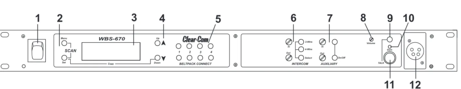
Controls and Connections - Front Panel
1. Power switch.
2. [Menu] and [Set] buttons– Used to select menus and set options on the LCD.
3. Backlit Graphics LCD (Liquid Crystal Display). 4. [Up] and [Down] buttons – Used to select base station
options on the LCD.
5. Beltpack Connect– Buttons used to enable or disable the respective receiver’s audio. GREEN LED = Audio en-abled, LED OFF = Audio disabled.
6. Intercom Controls -Wired intercom interface controls. Audio input and output level controls. 2-wire or 4-wire se-lect button with green LED indicator lights. Sese-lected LED will change to RED if the input levels are too high.
7. Auxiliary Controls - Wired auxiliary interface controls. Audio input and output level controls. GREEN LED = Aux. input enabled. LED will change to RED if the input levels are too high.
8. Headset Volume – Controls the volume to the headset connected to #12.
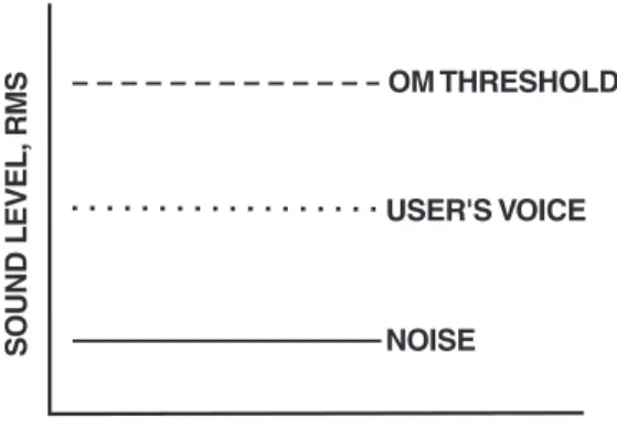
9. Talk/Overmod Light – LED is green when talk button #11 is active. A normal mic gain setting will cause the LED to flash red on the loudest speech levels. If the gain is too high, the LED will be red at normal speech volumes.
10.Microphone Gain – Adjusts the headset’s microphone gain. Adjusts so that the overmod light #9 flashes from green to red on loudest speech.
11. Talk Button– Press to enable the audio path from the local headset. LED #9 will turn green when enabled. A quick press and release latches button on. If the talk function is latched on, pressing the talk button again will turn it off.
12. Local Headset Connector– Male XLR connector. A dy-namic or electret headset microphone is automatically de-tected.
Figure 2 Local Headset Wiring
Gain Volume On/Off In Out AUXILIARY 2-Wire 4-Wire Select In Out BELTPACK CONNECT 1 2 3 4 Up Down Menu Set SCAN
1
2
3
4
5
6
7
8
9 10
11 12
INTERCOM WBS-670 Copy TALK Figure 1 WBS-670 - Front Panel (1) Microphone Shield (-) (2) Microphone Audio (+) (3) Headphone High (+) (4) Headphone Low (-)S
ection
2
Controls and Connections - Rear Panel
1. Receive Antenna- Female “TNC” Connector. Color band on antenna must match color dot on base station.
2. Transmit Power Switch – HIGH = Transmitter at full power. NORMAL = Transmitter 10dB below full power.
3. Transmit ON/OFF Switch– Turns the transmitter on or off.
4. I/C Select Switch– Set to the appropriate 2-wire intercom type being interfaced to the unit. Set to either Clear-Com®, RTS, or Telex®
5. Intercom – Interface to wired intercom system.
2-Wire – Male and Female 3-pin XLR connectors wired in parallel. The connectors are switched to the appropriate intercom configuration via the I/C Select Switch.
4-Wire – An RJ-45 type jack compatible with “Ma-trix” type intercom systems.
6. Auxiliary Input/Output – One 3-pin female XLR input connector and one 3-pin male XLR output connector.
7. Power– IEC receptacle. Accepts 100 – 240VAC, 50 – 60 Hz
8. Transmit Antenna - Female “TNC” Connector. Color band on antenna must match color dot on base station.
PUSH PUSH
1
2
3 4
5
6
7
8
RECEIVE HIGH ON NORM OFF TRANSMIT POWER I/C TELEX CLEAR-COMRTS INTERCOM 2-WIRE L O O P T H R U 4-WIRE AUXILIARY AUDIOINPUT OUTPUT POWER
100-240 VAC 50-60 Hz TRANSMIT WBS-670 FCC ID: B5DM516 CANADA 1321231218A . MADE IN U.S.A. R Intercom Systems Figure 3 WBS-670 - Rear Panel
WBS-670
Specifications
Overall
RF Frequency Range . . . 518 - 608 MHz, 614 - 740 MHz in 18 MHz TX and RX bands Power Requirements. . . 100-240 VAC, 50-60 Hz, IEC receptacle Temperature Range . . . -4° F to 130° F (-20° C to 55° C) Dimensions. . . 19.00” W x 1.72” H x 14.00” D (48.3 cm x 4.4 cm x 35.6 cm) Weight. . . 7 lbs 2 oz (3.24 kg) TX Antenna . . . 1/2 Wave (supplied), TNC Male Connector RX Antenna . . . 1/2 Wave (supplied), TNC Male Connector FCC ID: . . . B5DM516 Frequency Response . . . 300Hz-8kHz Four Wire Input. . . Level Adjustable (2 Vrms typical) Four Wire Output . . . Level Adjustable (2 Vrms typical) Telex®(AudioCom®) Intercom. . . Input/Output Level Adjustable (1 Vrms typical), Line impedance 300ê RTS Intercom . . . Input/Output Level Adjustable (0.775 Vrms typical), Line Impedance 200ê
ClearCom®Intercom . . . Input/Output Level Adjustable (1 Vrms typical), Line Impedance 200ê Auxiliary Input . . . Adjustable (2 Vrms typical) Auxiliary Output. . . Adjustable (2 Vrms typical into 600ê) Microphone input sensitivity . . . 9mV Local Headset Output . . . 40mW output into 600ê(1% Distortion)
Transmitter
Type . . . Synthesized Transmitter, 712 channels Transmit Power . . . 50 mW Max. (High), 5 mW (Normal) Modulation Type . . . FM Deviation . . . 40 kHz (35 kHz Europe) RF Frequency Stability . . . 0.005% Modulation Limiter . . . Peak-Responding Compressor Radiated Harmonics & Spurious . . . Exceeds FCC specifications
Receiver
Type . . . Dual Conversion Superheterodyne, four Independent Synthesized IFs, FM, 712 channels each RF Sensitivity . . . <0.8 µV for 12 dB SINAD Squelch Threshold . . . 20 dB SINAD IF Selectivity . . . 3 dB at 230 kHz Image Rejection. . . 70 dB or better Squelch Quieting . . . 90 dB RF Frequency Stability . . . 0.005% Distortion . . . <1% at full deviation
WTR-670 Beltpack
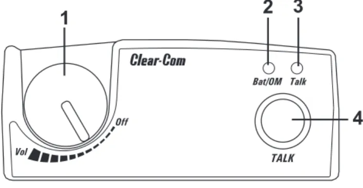
Controls and Connections - Top Panel
Figure 4 WTR-670 Top Panel
1. On/Off & Volume Control – Turns the beltpack power on and controls headset volume.
2. Bat/Overmod Light– Light will flash once when unit is turned on if the battery is good. If the light stays on, bat-tery is low. If the light does not flash, batbat-tery is dead. A normal microphone gain setting will cause the LED to flash at the beginning of most words at normal speech levels. If the gain is too high, the LED will be red during the complete word at normal speech levels.
3. Talk Light– LED is on when the talk button is active.
4. Talk button– Press to enable the audio path from the lo-cal headset microphone. The “TALK” LED, #3, will turn red when enabled. A quick press and release latches the talk function, unless latching has been disabled in soft-ware. Holding the button for over ½ a second will cause the audio path to be enabled only for as long as the button is held. If the talk function is latched on, pressing the talk button again will turn it off.
1
2
4
3
Bat/OM Talk Vol Off TALKS
ection
3
Controls and Connections - Rear Panel
Figure 5
WTR-670 Rear Panel/Connector/Antennas
1. [MENU] and [SET] buttons– Used to select menus and set options on the LCD.
2. LCD (Liquid Crystal Display)
3. [UP] and [DOWN] buttons– Used to select beltpack op-tions on the LCD.
4. Microphone Gain – Adjusts the headset’s microphone gain. Adjust so that the BAT/OM LED will flash at the be-ginning of most words at normal speech levels
5. Push-to-Talk/Push-to-Transmit Switch–
Push-to-Talk (PT TALK)– The transmitter is always on. No audio is sent unless the talk button is pressed. Recommended position.
Push-to-Transmit (PT TX)- The transmitter and au-dio paths are off except when the talk button is pressed.
6. Headset Connector – Male XLR connector. A dynamic or electret headset microphone is automatically detected by the beltpack and a bias voltage supplied if needed.
Figure 6
Headset Connector Wiring
7. Battery Latch– Press down to enable the battery pack to be released. While the latch is held down, slide the battery pack about 1/8 inch back, toward the latch, until it stops. Then lift out.
8. Receive Antenna – Screw type ¼-wave replaceable an-tenna. The receiver antenna is always the longer anan-tenna. Color dot on the screw end of the antenna must match color dot on antenna receptacle.
9. Transmit Antenna– Screw type ¼-wave replaceable an-tenna. Color dot on the screw end of the antenna must match color dot on antenna receptacle.
(1) Microphone
Shield (-)
(2) Microphone
Audio (+)
(4) Headphone
Low (-)
(3) Headphone
High (+)
MENU SET MIC PT TXPTTALK6
7
8
9
MENU SET MIC PT TX PTTALK2
1
3
4
5
WTR-670
Specifications
RF Frequency Range . . . 518 - 608 MHz, 614 - 740 MHz in 18 MHz TX and RX bands Power Requirements . . . 6 “AA” Cells Alkaline (NiMH optional) Current Draw. . . 140 mA (Push-to-Talk, Talk On) Temperature Range . . . -4° F to 130° F (-20° C to 55° C) Dimensions. . . 3.75”W x 5.05”H x 1.65” D (9.5 cm x 12.8 cm x 4.2 cm) Weight . . . 16 oz (454g) with alkaline batteries TX Antenna . . . 1/4 Wave (supplied), Screw type, Replaceable RX Antenna . . . 1/4 Wave (supplied), Screw type, Replaceable FCC ID: . . . B5DM515 Frequency Response . . . 300Hz-8kHz Microphone input sensitivity . . . 7 mV Local Headset Output . . . 40 mW output into 600ê(1% distortion)
Transmitter
Type . . . Synthesized, 712 channels Transmit Power. . . 50 mW Max. (auto-power reduction) Modulation Type . . . FM Deviation . . . 40 kHz (35 kHz Europe) RF Frequency Stability . . . 0.005% Modulation Limiter . . . Peak-Responding Compressor Radiated Harmonics & Spurious . . . Exceeds FCC specifications
Receiver
Type . . . Dual Conversion Superheterodyne, Synthesized, FM, 712 channels RF Sensitivity . . . <0.7 µV for 12 dB SINAD Squelch Threshold . . . 20 dB SINAD (About 1.0 µV) IF Selectivity . . . 3 dB at 230 kHz Image Rejection. . . 70 dB or better Squelch Quieting . . . 90 dB RF Frequency Stability . . . 0.005% Distortion . . . <1% at full deviation
Initial Equipment Set-Up
Unpacking
Unpack your Clear-Com® System. Below are the items that
should come with your base station and each belt pack.
WBS-670
WTR-670
Contact the shipper or your dealer immediately if anything is damaged or missing.
Quantity Description
1 WBS-670 Base Station
1 Operating Instructions
1 Power Cord
2 Antennas (one Transmit and one Receive)
1 Warranty Card 1 Screwdriver 1 Warning Card 4 Rubber feet Quantity Description 1 WTR-670 with Antennas 1 Battery pack 1 Instruction Sheet 1 Screwdriver 1 Warranty Card
S
ection
4
Antenna Connection
The base station is supplied with two (2) antennas. One 1/2-wave antenna for Transmit and one 1/2-wave for Receive. The antennas have TNC male connectors.
The frequency range of the antennas should match the receiver and transmitter of the base station. Match the color code on the antenna with the color code on the base station.
Attach the transmit 1/2-wave antenna to the antenna input re-ceptacle labeled “Transmit” on the right side of the rear panel. The antenna should be vertically aligned.
Figure 7
Attaching Transmit 1/2-Wave Antenna
Attach the receive 1/2-wave antenna to the antenna input re-ceptacle labeled “Receive” on the left side of the rear panel. The antenna should be vertically aligned.
Figure 8
Attaching Receive 1/2-Wave Antenna
Antenna Polarization
The Clear-Com®Wireless Intercom System is “Vertically
Po-larized”. This means both the transmitting and receiving an-tennas should operate in the vertical position.
Figure 9
Vertically Polarized Antennas
Distance between Antennas
The distance between the base station’s receive and transmit antennas is not adjustable when the antennas are connected di-rectly on the back of the unit.
The antennas can be remoted for better signal path.
NOTE:If your base station is to be located in a shielded rack mount enclosure or other poor RF location, you must remote the 1/2-wave antennas.
Antenna Placement
Proper antenna placement probably has the most effect on
your Clear-Com®Wireless Intercom System’s overall
perfor-mance. The following suggestions will result in optimum per-formance.
Proper placement of the beltpack can be critical. The antennas should be in the open. Bending the antennas up and placing the beltpack in a pocket, etc., will reduce system distance. It is suggested that the unit be worn on the belt or pocket with both antenna’s vertical for best operating range and perfor-mance.
Figure 10
Proper Dressing of the Antennas
TELEXCLEAR COM T e le x OFF BAT/O MT A LK VOL WTR-670 Gain Volume On/Off In Out AUXILIARY 2-Wire 4-Wire Select In Out BELTPACK CONNECT 1234 Up Down Menu Set SCAN INTERCOM WBS-670 Copy TALK
ANTENNAS SHOULD BE VERTICAL
T e le x OF F BA T/O M T A LK VOL WTR-670
Keep the distance between the base station and the beltpacks as short as possible. The greater the distance, the weaker the signal. Make sure the “signal paths” between the base station and beltpacks are unobstructed. You should be able to visibly locate the base station antennas at all times for best perfor-mance.
Figure 11
Distance Between base station and beltpack
Figure 12
Keeping Site Clear to Antenna
Attempting to operate the wireless intercom system through or around walls, ceilings, metal objects, etc. will reduce system range and performance.
Figure 13
Operating System Near Obstructions
DO NOT- mount the base station 1/2-wave antennas on, or next to metal, such as beams, walls with metal studs, equip-ment racks, etc. This also applies to the antennas when assem-bled directly to the Base Station. This will “detune” the antennas which can result in noise or loss of RF signal at the Base Station, see Figure 13.
700 FEET 100 FEET T e le x OF F BAT/O M T A LK VOL T e le x OF F BA T/O MT A LK VOL WTR-670 WTR-670 Gain Volume On/Off In Out AUXILIARY 2-Wire 4-Wire Select In Out BELTPACK CONNECT 1234 Up Down Menu Set SCAN INTERCOM WBS-670 Copy TALK T e le x OF F BA T/OM T ALK VOL WTR-670 T e le x OF F BA T/OM T ALK VOL WTR-670 Gain Volume On/Off In Out AUXILIARY 2-Wire 4-Wire Select In Out BELTPACK CONNECT 1234 Up Down Menu Set SCAN INTERCOM WBS-670 Copy TALK T ele x OF F BAT/OMT ALK VOL R WTR-670 Gain Volume On/Off In Out AUXILIARY 2-Wire 4-Wire Select In Out BELTPACK CONNECT 1234 Up Down Menu Set SCAN INTERCOM WBS-670 Copy TALK
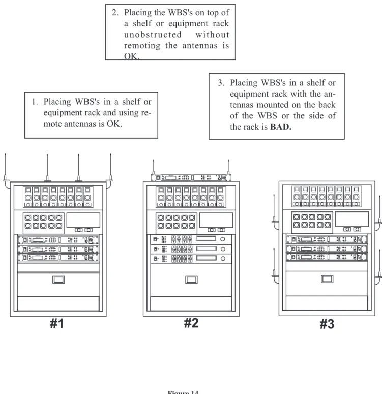
Figure 14 Antenna Placement
Improving Reception and Increasing
Range
Keeping the distance from the base station and beltpack as short, and unobstructed as possible will produce the most reli-able performance.
The base station is supplied with two antennas. This should provide satisfactory system performance in most applications. System range can be enhanced by remoting the 1/2-wave an-tennas.
#1
#2
#3
Gain Volume On/Off In Out AUXILIARY 2-Wire 4-Wire Select In Out BELTPACK CONNECT 1234 Up Down Menu Set SCAN INTERCOM WBS-670 Copy TALK Gain Volume On/Off In Out AUXILIARY 2-Wire 4-Wire Select In Out BELTPACK CONNECT 1234 Up Down Menu Set SCAN INTERCOM WBS-670 Copy TALK Gain Volume On/Off In Out AUXILIARY 2-Wire 4-Wire Select In Out BELTPACK CONNECT 1234 Up Down Menu Set SCAN INTERCOM WBS-670 Copy TALK Gain Volume On/Off In Out AUXILIARY 2-Wire 4-Wire Select In Out BELTPACK CONNECT 1234 Up Down Menu Set SCAN INTERCOM WBS-670 Copy TALK Gain Volume On/Off In Out AUXILIARY 2-Wire 4-Wire Select In Out BELTPACK CONNECT 1234 Up Down Menu Set SCAN INTERCOM WBS-670 Copy TALK Gain Volume On/Off In Out AUXILIARY 2-Wire 4-Wire Select In Out BELTPACK CONNECT 1234 Up Down Menu Set SCAN INTERCOM WBS-670 Copy TALK Gain Volume On/Off In Out AUXILIARY 2-Wire 4-Wire Select In Out BELTPACK CONNECT 1234 Up Down Menu Set SCAN INTERCOM WBS-670 Copy TALK1. Placing WBS's in a shelf or
equipment rack and using
re-mote antennas is OK.
2. Placing the WBS's on top of
a shelf or equipment rack
unobstructed
without
remoting the antennas is
OK.
3. Placing WBS's in a shelf or
equipment rack with the
an-tennas mounted on the back
of the WBS or the side of
the rack is
BAD.
Base Station Set-up
Location
Locate the base station with the front and rear of the unit ac-cessible so that switches may be set and connections made. Place the transmit and receive antennas on the base station. Make sure the antenna’s color band match the color dot near each antenna. See “Antenna Information” section for more in-formation on choosing a proper operating location.
Power Connection
Plug the supplied power cord into the unit. The base station has an IEC power receptacle that accepts 100 – 240 VAC, 50 – 60 Hz. The specific receptacle type is an IEC 60320/C14. The cord it accepts is an IEC 60320/C13. These cords are common and available through many retail hardware/electronic stores if the cord is lost.
Transmit Switches
There are two switches located on the lower left side of the rear panel. The upper switch sets the transmit power level to high or normal. The lower switch turns the transmitter on or off.
Transmit Power
Set the power level to normal if using the beltpacks at close to medium distances (<200 feet, 161m, line-of-sight) from the base station. Set the power level to high if using the beltpacks at a distance (>200 feet, 161m, line-of-sight) from the base station.
On/Off
Set the transmitter switch to on for normal use. In the off position the base station transmitter is disabled. Setting the switch to off will disables all the beltpacks from hear-ing anyone else or even their own sidetone.
TRANSMIT SWITCHES
INTERCOM SWITCH
INTERCOM
INTERFACE POWER CONNECTION
PUSH PUSH RECEIVE HIGH ON NORM OFF TRANSMIT POWER I/C TELEX CLEAR-COMRTS INTERCOM 2-WIRE L O O P T H R U 4-WIRE AUXILIARY AUDIO
INPUT OUTPUT POWER
100-240 VAC 50-60 Hz TRANSMIT WBS-670 FCC ID: B5DM516 CANADA 1321231218A . MADE IN U.S.A. R Intercom Systems Figure 15
Intercom Switch
The Clear-Com® wireless system can be interfaced to
Clear-Com, RTS TW, Audiocom® (Telex), Matrix and other
intercom (I/C) systems. Set the Intercom switch on the rear of the unit to the appropriate system and connect the system to the base station. The intercom channel on the rear of the base station has loop thru male and female XLR connections for two-wire systems and a RJ-45 type jack for four-wire systems. This switch only affects the two-wire intercom systems. The functions of the I/C XLRs change depending on the intercom selected. Please see Section 11 for pinout information of the different two-wire intercom systems.
Auxiliary Input/Output
The input and output 3-pin auxiliary connections are for sup-plying additional balanced audio into and receiving balanced
audio from the base station.The input and output auxiliary
audio is global.This means the input and output auxiliary au-dio is placed on the base local headset, beltpack(s) headsets andany wired intercom system interfaced to the base sta-tion.
Intercom Interface
Clear-Com®and Telex (Audiocom®) intercom systems require one cable for intercom. This interfacing is done through the I/C 3 pin XLR connectors on the rear of the unit.
RTS TW intercoms also only need to connect one 3-pin cable to one of the two intercom XLR connectors. Two channels of audio are carried on one cable for RTS. RTS channel 1 is placed on the intercom normally. Switch the rear-panel I/C switch to Clear-Com®to interface only to RTS audio channel 2. Once again, leave it in RTS to interface to only RTS audio Channel 1.
Four wire intercom systems require only one cable for the in-tercom to interface four wire inin-tercom to the base station. This interfacing is done through the I/C RJ-45 type jacks on the rear of the unit. See Figure 16 for the pinout of the RJ-45 jacks.
A modification document is available from Clear-Com for those who wish to modify the base station so that auxiliary in-put audio is heard only locally; base local headset and beltpack(s) headsets.
PIN 1 2 3 4 5 6 7 8
CONNECTED TO PIN 2
CONNECTED TO PIN 1
AUDIO OUT
AUDIO IN
-CONNECTED TO PIN 7
CONNECTED TO PIN 8
AUDIO OUT +
AUDIO IN +
AUXILIARY INTERFACE PUSH PUSH RECEIVE HIGH ON NORM OFF TRANSMIT POWER I/C TELEX CLEAR-COMRTS INTERCOM 2-WIRE L O O P T H R U 4-WIRE AUXILIARY AUDIOINPUT OUTPUT POWER
100-240 VAC 50-60 Hz TRANSMIT WBS-670 FCC ID: B5DM516 CANADA 1321231218A . MADE IN U.S.A. R Intercom Systems Figure 17
Base Station - Rear Panel Figure 16
Beltpack Set-up
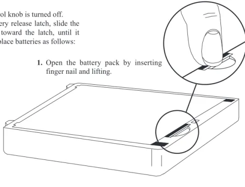
Battery Installation
Ensure that the On/Off volume control knob is turned off. Press down and hold down the battery release latch, slide the battery pack about 1/8 inch back, toward the latch, until it stops. Then lift battery pack out. Replace batteries as follows:
Figure 18 Battery Installation
1. Open the battery pack by inserting
finger nail and lifting.
3. Load new batteries following the polarity as shown in battery case
5. Be sure strap goes under batteries.
4. Start loading at the end of the case where the strap is attached to the case.
6. Tuck end of strap under door
when placing the battery cover back on the case.
2. Pull battery strap to remove low or dead batteries.
WARNING
Do not place an alkaline WTR bat-tery pack in any batbat-tery charger. Se-vere charger and battery pack damage may result.
Antenna Connection
The beltpack comes with two detachable, screw type, ¼ wave antennas. To attach the two antennas, screw into the recepta-cles at the bottom of the beltpack. The color dot on the screw end of the antenna must match the color dot on antenna recep-tacle. The longest antenna is the receiver antenna. It screws into the left receptacle if the beltpack is laying flat with the battery compartment face up and the antenna receptacles fac-ing you. The other antenna is the transmit antenna. New an-tennas can be ordered if desired, see the “Accessories” section.
Transmit mode
The rear panel located transmit switch has the following two modes:
Push-to-Talk (PT TALK) – Recommended position – The transmitter is always on. No audio is sent unless the talk switch is pressed.
Push-to-Transmit (PT TX) – The transmitter and audio paths are off except when the talk switch is pressed.
Headset Connection
Insert the headset plug into the XLR connector. See the head-set pinout in the “WTR-670 beltpack controls and connec-tions” section if this is not a Clear-Com®headset. A dynamic or electret headset microphone is automatically detected by the beltpack and a bias voltage supplied if needed.
MENU SET MICPT TXPTTALK MICROPHONE GAIN CONTROL TRANSMIT SWITCH HEADSET CONNECTION RECEIVE
ANTENNA TRANSMITANTENNA
BATTERY RELEASE LATCH
Figure 19 WTR-670 Rear Panel
Pre-Walk-Thru Checklist
Following the instructions fully to this point you have success-fully completed the following checklist:
❒
Located the base station properly.❒
Connected power to base station.❒
Connected the 1/2-wave antennas to the base station.Checked frequency range of the antennas with the fre-quency of the base station by correctly matching color codes.
❒
Connected 1/4-wave antenna to the beltpack. Checkedfrequency range of the antennas with the frequency of the beltpack by correctly matching color codes.
❒
Base station transmit power switches in the correctpo-sitions.
❒
Transmit mode switch on beltpack set correctly❒
Set wired intercom type correctly.❒
Connected headsets to base stations (if needed) and allbeltpacks.
❒
Connected the base station to any auxiliary audio,in-tercom or external P.A. system.
❒
Installed batteries in the beltpack.❒
If you missed any of the above instructions, go backand complete that instruction before going on.
S
ection
5
System Operation
Frequency Plan Overview
The WBS/WTR-670 has 36 factory-defined frequency groups and 12 user-programmable frequency groups. A Group de-fines the base-station transmit frequency and thus the receive frequency on all the beltpacks. A Channel defines a base-station receive frequency and thus a beltpack transmit frequency. A base-station receive channel that does not have a frequency set for it will have a dash to the right of it on the Group/Channel select screen. Details on setting frequencies may be found in the “WBS-670 Menu Structure” and “WTR-670 Menu Structure” instructions in this section.
Factory-Defined Groups
The 36 factory-defined groups were carefully chosen to avoid certain intermod products and various other possible sources of interference. The Groups are set and cannot be changed. A limited number of channels can be chosen from within these groups.
The first 24 factory-defined groups (01A – 12B) are “pair” groups that can be used for single (up to 4 beltpacks) and dual (up to 8 beltpacks) WBS-670 systems. They are arranged 01A, 01B, 02A, 02B…011B, 012A, 012B. A “pair” group, like 1A and 1B, have different base-station transmit frequen-cies, however, they both have the same eight base-station re-ceive channels from which to choose. Each channel represents a unique frequency. For example, one WBS-670 could be set on Group 02A and channels 01, 02, 03 and 04. The other WBS-670 could be set on Group 02B channels 05, 06, 07 and 08. As long as the channels are different, everything should be fine.
The next 12 groups (13 – 24) are single groups that primarily are used for single (up to 4 beltpacks) WBS-670 systems. The number of channels from which to choose from in these groups will vary from group to group.
User-Programmable Groups
The 12 user-programmable groups are initially empty. The transmit and receive frequencies are fully editable within these groups. In fact, factory-defined groups may be copied to user-programmable groups and then edited if desired. See the “WBS-670 Menu Structure” and “WTR-670 Menu Structure” instructions in this section for details on how to copy and edit frequencies.
System Quick Start
Follow the list below to quickly get a base station and beltpack(s) operating. When completed the user should have a base station and 1 to 4 beltpacks up and running with full oper-ational ability. The base station will be on Group 01A with its four receivers on channels 01, 02, 03 and 04. Each beltpack will be on Group 01A with a unique transmit channel number matching one of the base station receive channels.
1. Plug-in the base station via the supplied power cord and connect the antennas. The color dots on the base should match the color rings on the antennas.
2. Base-station rear-panel switches: Transmit power set to High and on.
3. Ensure base-station rear-panel IC switch matches attached wired intercom system. If used stand alone or connected to a 4-wire system then IC switch position is Not Applicable.
4. Press [MENU] as powering-up the base station. This will place it on group 01A and set the receives on channels: 01, 02, 03, and 04.
5. Place the front-panel IC “IN” and “OUT” level controls in the 12 o’clock position. Check that front panel IC is in 2-wire for AudioCom (Telex), RTS - TW and Clear-Com wired systems, and 4-wire for Matrix and stand-alone op-eration.
6. Place batteries in the beltpacks.
7. Remove the rear switch cover on the beltpacks. Set the beltpack rear-panel slide switch to push-to-talk (PT TALK).
8. Press [MENU] as powering-up each beltpack. This will place the beltpack on group 01A with the channel 01 flashing.
9. Use the [UP] and [DOWN] arrow buttons to change the channel to match a channel on the base station. Then press [SET]. If leaving on channel, just press [MENU]. Each beltpack should have a unique channel number.
10.The group/channel on the beltpack should now match the group and a receive channel on the base station. Nothing should be flashing on the beltpack screens.
11. Plug headsets into the beltpacks and set the microphone gain so the BAT/OM LED will flash at the beginning of most words at normal speech levels.
DONE.
S
ection
Base Station Operation
Power
If you have followed the instructions in Section 4, “Initial Equipment Set-Up”, you should now be ready to turn the base station on.
Set the base station power switch to the on position, by push-ing the top of the switch.The internal coolpush-ing fan will start im-mediately and the LCD display and front panel indicator lights will come on in five or six seconds.
Local Headset
Talk Button -Press to enable the audio path from the local headset. The TALK/O.M. LED will turn green when audio is enabled. A quick press and release latches on the button. If the talk function is latched on, pressing the talk button again will turn it off. If the local headset is not being used, the talk button should be off. This keeps additional noise out of the system.
Microphone Gain - Adjusts the headset’s microphone gain. Adjust so the TALK/O.M. LED flashes from green to red on loudest speech.
Volume -Adjust the volume to the headset by rotating the vol-ume control as required for a comfortable listening volvol-ume.
Beltpack Connect
Select the audio paths from the base station’s four receivers that you wish to enable. The corresponding LED above the select button is on when the audio path is enabled. If a beltpack user has their beltpack connect path off at the base, that user will no longer hear their sidetone and their audio will not be passed to anyone. The user will still be able to hear everyone. The selec-tion is retained in non-volatile memory, so it will come up where last left if the unit is power cycled.
Always disable unused audio receive paths. This reduces the chances that external RF noise can get onto the audio buses via an open receiver.
Intercom
Intercom Select Button- Press the [SELECT] button to choose between 2-wire or 4-wire intercom systems. The green LED will indicate the current mode of the intercom channel. If the base station is connected to a 2-wire sys-tem, such as Audiocom (Telex), RTS TW or Clear-Com, set the intercom to 2-wire. If it is connected to a four-wire system, such as Matrix type system, set the in-tercom to 4-wire. The selection is retained in non-volatile memory, so it will come up where last left if the unit is power cycled.
In Level Control - Adjusts the audio level of the wired intercom system’s input to the base station.
Out Level Control- Adjusts the audio level of the base station’s output to the wired intercom system.
If the base station is used stand-alone with no wired intercom system connected, it must be set in the 4-wire mode. The 2-wire mode requires that a wired intercom system or appro-priate load be connected to the intercom. If not loaded, a large gain increase will take place in the unload intercom channel which may be high enough to produce a loud “howling” sound.
Auxiliary
Auxiliary Input Select Button - Press the [SELECT] button to turn on or off the auxiliary input to the base sta-tion. The selection is retained in non-volatile memory, so it will come-up where last left if the unit is power cycled.
In Level Control - Adjusts the audio level of the wired auxiliary system’s input to the base station.
Out Level Control- Adjusts the audio level of the base station’s output to the auxiliary XLR plug.
The auxiliary output is always available at the back-panel out-put XLR. It cannot be switch on or off like the inout-put. Both the input and output are balanced audio ports. Auxiliary input and output audio is global. See Section 4 for more details.
POWER PORTABLE STATIONCONNECT
INTERCOM AUXILIARY LOCAL HEADSET 3 Gain Volume On/Off In Out AUXILIARY 2-Wire 4-Wire Select In Out BELTPACK CONNECT 1 2 3 4 Up Down Menu Set SCAN INTERCOM WBS-670 Copy TALK
Display Contrast
The LCD’s (Liquid Crystal Display) contrast is set from the factory to a standard level. However it is possible for the user to adjust the contrast if desired. The contrast control is inter-nal to the WBS-670 unit near the front panel. The cover must be removed for access to this control. Please see Figure 20 for the location. Figure 20 LCD Contrast
V
D1
101
FRONT
BACK
R1
101
WBS-670 Menu Structure
Main Screen Flowchart
The following contains the base station menu structure and references the pages in which further detail of that menu may be found.
Clear-Com
Operating Screen - Pg. 6-5 Power-Up Screen - Pg. 6-5
Group/Channel Select Screen - Pg. 6-6 [MENU]
Group/Frequency Select Screen - Pg. 6-7 [MENU]
Frequency Edit Screen - Pg. 6-8 [MENU] (User-Programmed Only) [MENU] Action [MENU] No Action [MENU] + [SET]
Scan
Scan Start-up/Search Screen - Pg. 6-9
[MENU] or [SET]
Scan Result Screen - Pg. 6-9
[MENU] S Group 25u 4 R1 Tx Tx Tx 2 3 On Tx Group 25u 4 R1Ch 01 Ch 02 Ch 03 Ch 04 2 3 Group 25u 4 R1705.150 565.350 707.850 710.100 715.300 2 3 Group 25u Freq Edit 4 Ch1705.150 565.350 707.850 710.100 715.300 2 3 2 Group 03A OK?=[SET] Next R C60001 01 05 02 06 03 04 08 no tx On Tx Tx Tx B40001
Other Special Key Sequences:
Lockout . . . 6-10 Copy . . . 6-10 1st Use Default . . . 6-10 Factory Default . . . 6-10
NOTE:Pressing [MENU] within a screen after action has occurred escapes from that action and places the user at the current screen. Any editing that had been done since [SET] had been pressed is aborted.
Power-Up Screen
•
This screen is displayed only on power-up, first use de-fault, and factory default.•
The 1st upper-right-corner number displays the base’ssoftware revision. The version number increments for changes in operational software.
•
The 2nd upper-right-corner number displays the base’schannel map (frequency plan) version. The version num-ber increments for changes in the channel map.
•
Once the power-up screen is displayed, it will change to the operating screen after a few seconds.Operating Screen
•
Screen is displayed after power-up screen.•
System will revert to this screen if no activity is detected on the LCD display buttons after 3 minutes.•
Screen displays current status of the system.Beltpack Activity Code Definitions:
Clear-Com
RS
C60001
B40001
Group 03A
T1
4
R1
tx
On
Off
Tx
Tx
Operating Screen
2
3
Tx
no
no tx = No Beltpack Transmit Carrier Detected Off = Receiver is not selected on front panel Tx = Beltpack is on
Group / Channel Select
The Group/Channel select screen allows the user to change the group and select from a pre-determined number of channels on each receiver.
•
Hit [MENU] once to enter the Group / Channel Select Screen from the operating screen.•
Hit [SET] to enter group edit. The group number will start flashing. If [SET] is hit again without hitting the arrows, the display will go to receive 01 channel edit.NOTE:A channel that does not have a frequency set for it will have a dash to the right of it on the group/channel select screen.•
The [UP] / [DOWN] arrows will change the group num-ber. Hit [SET] again to set the group that was flashing. Now the group number will stop flashing and R1’s chan-nel number will start to flash.•
The [UP] / [DOWN] arrows will change the receive chan-nel number. Hit [SET] to set the chanchan-nel that was se-lected. Now the second channel number will start to flash. If [SET] is hit again without hitting the arrows, the dis-play will go to the next channel number.•
After the last receive channel is decided upon, hitting [SET] will set that channel in the unit and start you over at the beginning of the group/channel select screen with nothing flashing.•
Hitting [MENU] will take you to the group/frequency se-lect screen. NOTE: Hitting [MENU] after activity has oc-curred within the screen will return to the group/channel select screen with nothing flashing. Any change that had been done before the last [SET] was pressed will be aborted.•
Setting two channels the same is not allowed. If a channel is already set on the screen, the user no longer has that channel as an option to set into one of the other receivers.Group 14
T1
4
R1
Ch 01
On
Ch 02
Ch 03
Ch 04
Group / Channel Select
2
3
Tx
Group 14
T1
4
R1
Ch 01
On
Ch 02
Ch 03
Ch 04
2
3
T1
Group 15
T1
4
R1
Ch 01
On
Ch 02
Ch 03
Ch 04
2
3
Group 15
T1
4
R1
Ch 05
On
Ch 02
Ch 03
Ch 04
2
3
[SET] [UP] / [DOWN] [SET] [UP] / [DOWN] [SET]Group 15
T1
4
R1
Ch 05
On
Ch 06
Ch 07
Ch 08
2
3
Group 15
T1
4
R1
715.000
569.700
716.700
719.700
721.600
2
3
[MENU] [UP] / [DOWN][SET] (Last Rx Changed)
END
Tx
Tx
Tx
Tx
Tx
Group / Frequency Select
The Group/Frequency select screen allows a user to set the group and select from a pre-determined number of frequencies on each receiver. Each frequency displayed on the right half of the screen corresponds to a channel number in the Group/Channel Screen.
•
Press [MENU] twice to go to the Group / Frequency Se-lect screen from the operating screen. Hit [SET] to start the group number flashing.•
Press the [UP] / [DOWN] arrows to change the group number. The frequencies listed will reflect what is cur-rently in that group. Hitting [SET] will select the group and start the selecting of predetermined frequencies within that group. The R1 frequency will start flashing.NOTE:The group number sets the transmit frequencies of factory defined groups and these are not editable. In user-programmed groups these are editable from the fre-quency edit screen.
•
Pressing the [UP] / [DOWN] arrows will change the fre-quency of “R1” to the pre-defined frequencies available. Hitting [SET] will accept the change and start you editing the next channel. If you had not hit the arrow keys when the frequency was flashing, but instead hit [SET], you would have skipped to the next frequency to edit.•
After the last receive frequency is decided upon, hitting [SET] will save that last frequency and start you over at the beginning of the group/frequency select screen with nothing flashing.•
Pressing [MENU] will take you to the operating screen if this is a factory-defined group. If within a user pro-grammed group, you will be taken to the frequency edit screen. NOTE: Hitting [MENU] after activity has oc-curred within the screen will return to the group/fre-quency edit screen with nothing flashing. Any change that had been done before the last [SET] was pressed will be aborted.Group 15
T1
4
R1
715.000
569.700
716.700
719.700
721.600
Group / Frequency Select
2
3
T1
Group 14
T1
4
R1
713.200
563.100
716.100
718.600
721.600
2
3
Group 14
T1
4
R1
563.100
2
3
Group 14
T1
4
R1
563.100
2
3
[UP] / [DOWN] [SET] [UP] / [DOWN][SET] (Last Rx Changed) [UP] / [DOWN] [SET]
716.100
718.600
721.600
704.200
704.700
708.300
709.500
704.200
Group 14
T1
4
R1
On
2
3
T1
Tx
[MENU]Tx
Tx
no tx
ENDno tx
Tx
Tx
Tx
Tx
Frequency Edit
(User-Programmed Groups Only)
This menu only occurs for user-programmable groups or when copying to a user-programable group. The Frequency Edit screen allows the user to set the group transmit frequency and receive channel frequencies of a user-programmable group.
•
Press [MENU] three times to go to the frequency select screen from the operating screen. Press [SET] to start the group number flashing. This screen allows the user to set the group and frequencies of user-programmed groups only.•
Press the [UP] / [DOWN] arrows to change the group number. The frequencies listed will reflect what is cur-rently in that group. Dashes will be displayed in any slots that are not defined yet. Pressing [SET] will select the group and start the selecting of frequencies within that group. The Tx frequency will start flashing.•
Pressing the [UP] / [DOWN] arrows will change the fre-quency of “Tx” in 25kHz steps. Pressing [SET] will ac-cept the change and start you editing Ch1. If you had not hit the arrow keys when the frequency was flashing, but instead press [SET], you would have skipped to the next frequency to edit.•
After editing the transmit and the receive channel fre-quencies, pressing [SET] will save that last frequency and send you over to the beginning of the group/frequency select screen with nothing flashing. NOTE:Once the end of the displayed channel list is reached, the last displayed channel location will scroll to allow the user to edit the re-maining channels.•
After action has occurred in the frequency edit screen hit-ting [MENU] will take you one menu back to the group/frequency select screen so that the user may see what frequencies the base receivers are now on. If no ac-tion had occurred, then pressing [MENU] will take you to the operating screen.NOTE:Besides a group change, any editing that occurs within this screen to frequencies DOES NOT take effect until the user exits the screen via setting the last channel or pressing [MENU].Group 25u
Freq Edit
T1
4
Ch1
705.150
565.350
707.850
710.100
715.300
2
3
Tx
Group 27u
Freq Edit
T1
4
Ch1
705.150
567.800
707.850
710.100
715.300
2
3
Tx
T1
Group 27u
Freq Edit
T1
569.350
10
8
9
Tx
[UP] / [DOWN]
[SET]
[UP] / [DOWN]
[SET]
720.550
721.350
721.900
718.550
Group 27u
T1
4
R1
569.350
2
3
Tx
[SET] or [MENU]
(Last Ch Changed)
710.550
714.225
716.800
705.950
Ch7
END
Frequency Edit
Scan
Scan performs a frequency scan of the factory-defined and any set-up user-programmable groups in order to find the group with the highest number of clear receive channels. After about 20-30 seconds, the group with the highest number of clear re-ceive channels will be displayed. The next best group and so forth may be accessed with the [DOWN] and [UP] arow but-tons.
•
Press and hold [MENU] + [SET] for three seconds to en-ter Scan. The base station will now start searching all groups for the ones with the greatest number of receiver channels clear of interference.•
Scan will display the group that has the most interference free receive channels. These clear channels are displayed on the right half of the screen. Press [SET] to place the base station on this group and return to the operating screen. The first four receive channels displayed will be the ones set for the group. The [UP] / [DOWN] buttons may be used to select the next best group and so forth.Scan
Group 03A OK?=[SET] Next 01 05 02 06 03 04 08 Group 04b 01 05 OK?=[SET] Prev Next 06 03 04 08 [DOWN] [SET] Group 04b 4 R1 On 2 3 Tx Tx Tx Tx no tx ENDScan
Special Key Sequences
Lockout
•
Press [UP]+[DOWN] for 3 seconds to lock or unlock the base station. Pressing [MENU] will still function to view screens, but [SET] will no longer start any editing. Scan, First use, Factory default are no longer accessible. The in-tercom front panel 2-wire/4-wire selection is also locked into place. A padlock icon will be displayed on the second line of the display to the far left as an indication that the base station is locked out.Copy
•
Press [SET]+[DOWN] for 3 seconds to copy any cur-rently displayed group to a user-programmable group. Copy can be done from the group/channel select, group/frequency select, or frequency edit screen. Once pressed, the words, “Copy to” are displayed on the screen with the first empty user-programmable group flashing. If all the user-programmed groups were full, than the first programable group is displayed. The [UP] or [DOWN] buttons may be used to select a different user-programmable group if desired. Pressing [SET] pastes frequencies/chan-nels to the group and take the user to the frequency edit screen with "Tx” flashing.1
stUse Default
•
Press [MENU] while turning on the base station to enter the 1stuse default setup screen. This places the unit ongroup 01A with the four receivers set to channels 1- 4 of the group. Any user-programmed frequencies that had been entered previously are retained. If lockout had been activated, the beltpack comes up where it was last left regardless of [MENU] being pressed on power-up.
Factory Default
•
Pressing all four buttons [MENU]+[SET]+[UP]+[DOWN] at the same time for 3 seconds places the unit on group 01A with the four receivers set to channels 1 – 4 of that group. This is just like base station 1stuse default, exceptthatall user-programmed frequencies that had been en-tered previously are erased.This function may take sev-eral seconds. If lockout had been activated, the beltpack comes up where it was last left regardless of these four keys being pressed.
Beltpack Operation
Power / Local Headset Volume
Turn the beltpack power on by rotating the knob CW. Adjust the volume to the headset by rotating the volume control as re-quired for a comfortable listening volume.
Battery Check
When the beltpack power is turned on by rotating the knob, the BAT/OM LED will flash once if the battery is good. If the LED stays on, the battery is low. If the LED does not flash, the battery is dead.
Talk Button
Press the talk button to enable the audio path from the headset microphone. The TALK/OM LED will turn red when audio is enabled. A quick press and release latches the talk function unless latching has been disabled. Holding the button for over ½ a second will cause the audio path to be enabled only for as long as the button is held. If the talk function is latched on, pressing the talk button again will turn it off. See the “Talk Button Latching/Non-Latching” instructions in Section 6 to learn how to enable/disable latching of the talk button.
Microphone Gain
Adjusts the headset’s microphone gain. Adjust so the TALK/OM LED flashes red at the beginning of most words at normal speech levels. If the input is too large, the LED will be red during the complete word at normal speech level. The peak-responding au-dio limiter in the beltpack is very tolerant of high input auau-dio lev-els. Even when the microphone gain is maximized, and headset volume reduced to make up for the louder audio, the audio will still sound good and not clipped.
POWER
LOCAL HEADSET VOLUME
MENU SET MICPT TXPTTALK TALK BUTTON MICROPHONE GAIN BATTERY CHECK Bat/OM Talk Vol Off TALK Figure 21
WTR-670 Menu Structure
Beltpack Menu Structure
[MENU]
S20001
C60001
03A 01
Power-Up Screen - Pg. 6-13
Group/Channel Screen - Pg. 6-14
GP
CH
[MENU]
704.200
Transmit Screen - Pg. 6-15
TX
[MENU]
570.300
R1
Receive Screen - Pg. 6-16
Clr Scn
GP
04A Scn
GP
[MENU]
+
[SET]
Scan Search Screen - Pg. 6-17
Scan Result Screen - Pg. 6-17
[MENU]
or
[SET]
The following contains the main beltpack menu structure and refer-ences the pages in which further detail of that menu may be found. All beltpack features and special key sequences can only be done from the group/channel screen.
Beltpack Feature Enable/Disable Menus:
Talk Button Latching/Non-Latching. . . 6-18
Other Special Key Sequences:
Lockout . . . 6-18 1stUse Default. . . 6-18
Factory Default . . . 6-18
NOTE: Pressing [MENU] within a screen after action has occurred escapes from that action and places the user at the current screen. Any editing that had been done since [SET] had been pressed is aborted.
Page Page
Power-Up Screens
•
The first screens displayed when the beltpack is powered up are the software and channel map version screens.•
The 1stscreen displayed indicates the beltpack’s softwareversion number. It is displayed for about one second.
•
The 2nd screen displayed indicates the beltpack’s channel map (frequency plan) version number. It is displayed for about one second.•
The final screen displayed is the group/channel screenEND
S20001
C60001
03A 01
GP
CH
Power-Up Screens
Group / Channel Screen
The Group/Channel screen allows the user to change the group and select from a pre-determined number of transmit channels.
•
The screen displayed after the beltpack power-up screens.•
Press [SET] to edit the channel number. The channel number will start flashing.•
Use the [UP]/[DOWN] arrow buttons to change the chan-nel number.•
Press [SET] to place the beltpack on the channel selected. Once set is pressed, the beltpack transmitter will move to that frequency and nothing will be flashing. Now press [SET] twice to enter group edit.•
Use the [UP]/[DOWN] arrow buttons to change the group number.•
Press [SET] to place the beltpack on the group selected. Once set is pressed, the unit returns to the group/channel display with nothing flashing.•
Pressing [SET] once more will start the editing sequence over again. Pressing [MENU] during the group edit will end editing and send the user back at the group/channel screen without any changes. This applies to channel edit-ing too.03A 01
CH
03A 01
GP
03A 01
CH
03A 01
GP
CH
03A 02
GP
CH
03A 02
GP
CH
05b 02
GP
CH
05b 02
GP
[SET]
[UP]/[DOWN]
[SET]
then [SET] twice more
[UP]/[DOWN]
[SET]
END
Transmit Screen
The Transmit screen allows the user to set the beltpack trans-mit frequency. Factory-defined groups will allow only a set number of pre-defined frequencies to be selected. User-programmable groups will allow the user to change the frequency in 25kHz steps.