MiVoice Border Gateway
Installation and Maintenance Guide
SEPTEMBER, 2015
RELEASE 9.1
ii
NOTICE
The information contained in this document is believed to be accurate in all respects but is not warranted by Mitel Networks™ Corporation (MITEL®). The information is subject to change without
notice and should not be construed in any way as a commitment by Mitel or any of its affiliates or subsidiaries. Mitel and its affiliates and subsidiaries assume no responsibility for any errors or omissions in this document. Revisions of this document or new editions of it may be issued to incorporate such changes.
No part of this document can be reproduced or transmitted in any form or by any means - electronic or mechanical - for any purpose without written permission from Mitel Networks Corporation.
TRADEMARKS
Mitel is a trademark of Mitel Networks Corporation.
Windows and Microsoft are trademarks of Microsoft Corporation. Linux is a registered trademark of Linus Torvalds.
The terms "ssh" and "Secure Shell" are trademarks of SSH Communications Security Corp. Trend Micro is a registered trademark of Trend Micro Incorporated.
VMware, VMware vMotion, VMware vCloud, VMware vSphere, ESX, and ESXi are trademarks of VMware Incorporated.
Other product names mentioned in this document may be trademarks of their respective companies and are hereby acknowledged.
This product includes software developed by the OpenSSL Project for use in the OpenSSL Toolkit. (http://www.openssl.org/).This product includes cryptographic software written by Eric Young ([email protected]). This product includes software written by Tim Hudson ([email protected]). To obtain the source code of third-party components licensed under the GNU General Public License or Lesser General Public License, please e-mail [email protected].
For a detailed list of third-party license content, see the Mitel Standard Linux Installation and Maintenance Guide available at Mitel OnLine.
MiVoice Border Gateway Installation and Maintenance Guide September 2015
®,™ Trademark of Mitel Networks Corporation © Copyright 2015, Mitel Networks Corporation
OVERVIEW ... 1
Feature Support ... 1
What’s New in this Release... 2
Release 9.1 ... 2
NETWORK PROFILES ... 3
Server-Gateway Configuration on Network Edge ... 3
Server-only Configuration on Network DMZ ... 4
Server-only Configuration on Network LAN ... 5
Server-Gateway Configuration with Bridged Interface ... 6
INSTALLING MIVOICE BORDER GATEWAY SOFTWARE ... 8
Before You Begin ... 8
Collect Site Information ... 8
Installing on a Physical Server ... 9
Download Software from Mitel Online ... 9
Build CD/DVDs from the Software ... 10
Install and Configure MSL Software ... 10
Install MBG Software on an Online system ... 10
Install MBG Software on an Offline System ... 11
Installing in a VMware Virtual Environment ... 12
VMware Resources ... 12
Installation Requirements ... 13
Pre-installation Checklist ... 14
Collect Properties ... 15
Deploy Virtual MBG Appliance ... 17
Configuration ... 20
Installing in a Microsoft Hyper-V Virtual Environment ... 20
Limitations ... 21
Disabling the MBG Service ... 21
Enabling the MBG Service ... 21
TELEWORKER SERVICE ... 22
Corporate Location Requirements... 22
Hardware ... 22 Software ... 23 Communication Platforms ... 23 Phones/Devices ... 23 License Requirements ... 23 Software Assurance ... 24
iv
Firewall Requirements ... 24
Support for HTML Applications ... 24
Remote Location Requirements ... 25
Phones/Devices ... 25
Network Parameters ... 25
Router/Internet Gateway ... 26
Configure Teleworker Service ... 26
Configuring the Teleworker Service on MBG ... 26
Provisioning MiNet Devices ... 27
Provisioning SIP Devices ... 29
Bulk Provisioning of MiNet and SIP Devices ... 30
SIP TRUNKING ... 31
Other Features ... 31
Before You Begin ... 32
Configuration Overview ... 32
Network Requirements ... 32
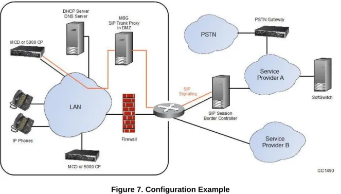
Configuration Example ... 33
Configure SIP Trunking ... 33
Configuring the MiVoice Business (3300 Controller) to Support SIP Trunks ... 33
Configuring the MiVoice Office 250 to Support SIP Trunks ... 35
Configuring the MX-ONE to Support SIP Trunks ... 36
Adding a SIP Trunk to MBG ... 37
Editing a SIP Trunk on MBG ... 39
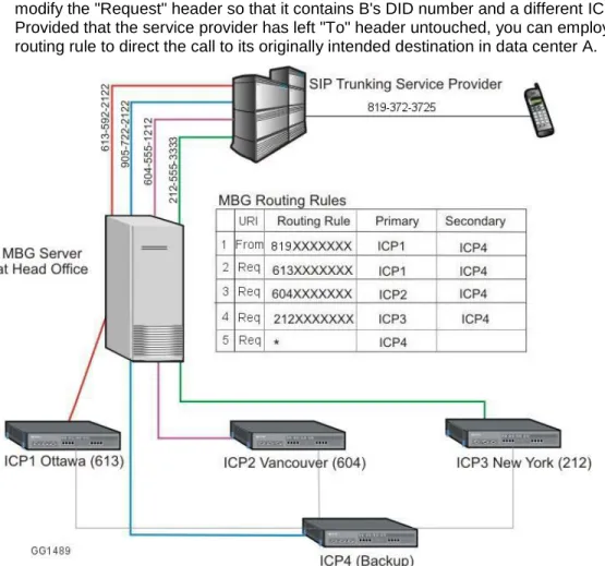
Configure DID Routing Rules for SIP Trunking ... 39
Configuration Example ... 39
Adding a DID Routing Rule ... 40
Editing a DID Routing Rule ... 41
DID Routing Rule Format ... 41
Valid Characters for DID Routing Rules ... 42
Sample DID Routing Rules ... 42
REMOTE PROXY SERVICES ... 43
Overview... 43
Web Proxy ... 43
Remote Management Service ... 43
When to Use the Web Proxy ... 44
Configurations ... 44
Basic Operation ... 45
Basic Configuration Overview ... 46
Multiple Account Setup ... 46
Firewall ... 47
Requirements for Audio, Web and Video Conferencing ... 48
DNS ... 48
Message Flow for Web Traffic... 49
Message Flow for Web Conferencing (Collaboration) Requests ... 50
Firewall ... 51
Configure LAN Servers on the Web Proxy ... 52
Configure Users for Remote Management ... 54
Configure MiVoice Business Support ... 55
Web Proxy with Multiple LAN Servers ... 57
Security Certificate Not Trusted ... 59
SECURE RECORDING CONNECTOR SERVICE ... 60
Direct Call Recording ... 60
Indirect Call Recording ... 60
Requirements ... 61
Phones/Devices ... 61
Firewall ... 61
DHCP for Direct Call Recording ... 61
Upgrading from SRC 2.2 to MBG 6.0 or later ... 62
Configuration ... 62
Enrolling the Call Recording Equipment ... 62
Handling Certificate Requests ... 63
CLUSTERING ... 63
Cluster Licensing ... 64
Cluster Hardware ... 64
DAISY CHAINING MBG SERVERS (TELEWORKING) ... 66
Setting up Daisy Chained Servers... 66
Daisy Chaining to Enforce Strict Firewall Rules ... 68
UPGRADING SOFTWARE AND LICENSES ... 69
Upgrading MiVoice Border Gateway Software ... 69
Upgrading a Physical MBG with CD/DVD or USB ... 69
Upgrading a Physical MBG with Remote Fresh Installation (RFI) Blade ... 70
Upgrading a Virtual MBG on VMware ... 71
Upgrading a Virtual MBG on Hyper-V ... 71
Upgrading a Cluster Setup ... 72
vi
Supporting Documentation ... 74
MBG AND EMERGENCY SERVICES ... 75
OVERVIEW
The MiVoice® Border Gateway (MBG) is the evolution of the Mitel Teleworker Solution to a platform for the secure deployment of multiple services in a variety of network configurations. MBG provides the following services:
Teleworking: Secure remote MiNET and SIP access for IP phones on the MiVoice Business platform. Also NAT traversal for tenant offices for the Multi-instance MiVoice Business application.
Secure call recording: Call recording solution that allows third-party recording equipment to record Mitel encrypted voice streams.
SIP trunking: An outbound proxy for SIP trunking from internal MiVoice Business platforms to external third-party SIP providers.
Web Proxy Domain: A reverse proxy that provides access to hosts on a corporate LAN for clients on the Internet.
Remote Management Service: Provides administrative-level access control to the MiVoice Business and MiCollab management web interfaces using password authentication while restricting access to all other parts of the enterprise network. This guide provides information about the requirements and installation procedures of the MiVoice Border Gateway.
Note that the MBG interface supports ASCII encoding, enabling the entry of unaccented characters from the English alphabet. In a future release, the interface will support UTF-8 encoding, enabling the entry of a wide range of accented and special characters.
FEATURE SUPPORT
FEATURE MIVOICE BUSINESS MIVOICE OFFICE 250 MIVOICE MX-ONE MIVOICE 5000 MIVOICE OFFICE 400 MiNet teleworker Yes Yes No1 No1 No1 SIP teleworkerYes Yes Yes2 Yes3 No
SIP Trunking Yes Yes Yes No No
Call recording Yes No No No No
Remote Management Service
Yes4 No No No No
1. This platform does not support the MiNet protocol.
2. This platform supports MiCollab Client and 68xxi SIP devices. 3. This platform supports MiCollab Client SIP devices.
4. This feature is used to grant access to the PBX's administrative interfaces.
5. 6.
WHAT’S NEW IN THIS RELEASE
Release 9.1
System Enhancements (included with MSL Release 10.3):
- MBG 9.1 is supported as a 64-bit application on the 64-bit distribution of MSL Release 10.3. MBG is no longer available as a 32-bit application, and therefore cannot be deployed on older, 32-bit versions of MSL.
- To install MBG 9.1 on a physical server, you must do a complete system backup and then perform a fresh install of the MSL operating system. The installation can be done manually or using the Remote Fresh Install (RFI) blade from the Blades panel. After installation is complete, you must perform a database restore if you have opted for the manual installation method.
MBG now supports:
- New MiCollab Client (Next Generation) SIP Softphone. - New ICP types: MiVoice 5000 and MiVoice MX-ONE. - SIP trunks on the MiVoice MX-ONE.
- SIP devices on the MiVoice 5000 and MiVoice MX-ONE.
For configuration instructions, please refer to the relevant product documentation.
PING Redirect for MiNET sets: When this feature is enabled, if a MiNET set
experiences difficulty connecting to a clustered MBG, the set will be required to transmit a PING message and wait for a successful response prior to being redirected.1
UTF-8 Support: MBG supports UTF-8 character encoding, enabling the use of most European and Asian languages in text-entry fields and CSV files. Note: In this release, the administrative interface for Remote Proxy Services does not support UTF-8 encoded characters.
SIP Enhancement: To secure the SIP media stream for end-to-end connections, MBG now supports standards-based Secure Real-time Transport Protocol (SRTP) on the ICP side as well as the set side. MBG now also supports SRTP on SIP trunks.
Diagnostics and Troubleshooting Enhancements:
- The new IP Blocking feature enables you to "white list" and "black list" entire networks to ensure that MBG only allows legitimate connections.
- The MBG Metrics screen has been designed to facilitate ease of use. It also contains statistics and data for a new range of functions.
1 The "Ping Before Redirect" feature is intended to resolve a problem which occurs when a clustered MBG becomes unreachable, but other MBGs in the cluster continue to redirect sets to that node (as part of load balancing) because they cannot detect the networking or routing problem that may be causing the problem.
When this feature is enabled, MBG first selects a set to be load balanced and then asks it to PING a new MBG. If a response is received, MBG will redirect the set to the new node. If a response is not received, MBG will wait for a period of time before restarting the process.
NETWORK PROFILES
MBG provides three preset Network Profiles for streaming addresses. You can choose the profile that applies your particular configuration or you can create a custom profile by manually entering the set-side and ICP-side IP addresses.
The default Network Profiles provide the following preset values: NETWORK PROFILE DEFAULT SET SIDE IP ADDRESS
FOR RTP STREAMING DEFAULT ICP SIDE IP ADDRESS FOR RTP STREAMING Server-gateway on
network edge
WAN IP address LAN IP address
Server-only on network DMZ
Public IP address as seen by the AMC
Public IP address as seen by the AMC
Server-only on network LAN
LAN IP address LAN IP address
Note: Improper selection of network profile can result in one-way audio or no audio at all.
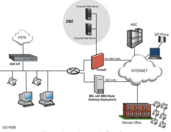
SERVER-GATEWAY CONFIGURATION ON NETWORK EDGE
In this configuration, the server functions a firewall/Internet gateway with two Ethernet interfaces. One interface is connected to the external network (Internet) while the other is connected to the internal network. The firewall provided by the MBG server is not
configurable. All default data traffic initiated inside the network is allowed while data traffic initiated outside the network is denied.
When you select this network profile, the system will program the RTP streaming addresses of the MBG as follows:
ICP-side streaming address = LAN interface address
set-side streaming address = WAN interface address
This setup enables you to provide prioritization for voice traffic by programming the maximum capacity of the MBG’s WAN links using the “Bandwidth Management” feature.
Although it is technically feasible to install services such as MICOLLAB on the gateway, it is not recommended. For optimum security, services should be located in the DMZ or LAN. The external (WAN) address of the server MUST be:
dedicated to the MBG Solution
publicly routable
reachable from the Internet and the internal network (that is, the server should not reside behind a NAT device)
Figure 1. Server-Gateway Configuration
MBG can also be implemented with an existing firewall on the network edge, as illustrated above. In this example, MBG serves as a gateway for MBG traffic while the second firewall handles non-MBG traffic.
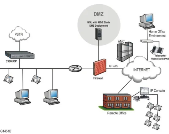
SERVER-ONLY CONFIGURATION ON NETWORK DMZ
In this configuration, the server is installed in the Demilitarized Zone (DMZ) of a customer’s existing firewall. It acts only as a server and is protected from Internet exposure by the existing firewall.
On the MBG, configure the LAN interface with an IP address that is:
dedicated to the MBG solution
private (allocated from the firewall's DMZ network range)
reachable from the internal network.
On the enterprise firewall, configure the WAN interface with an IP address that is:
dedicated to the MBG Solution
publicly routable via the firewall
reachable from the Internet and the internal network.
When configuration is complete, the system will use the public, post-NAT address of the server for both the set-side and ICP-side streaming addresses of the MBG. To determine this address, access the MSL Server Manager, select Review Configuration and examine the Internet Visible IP Address field.
Note: In a DMZ configuration, the firewall is the gateway for all traffic and has three interfaces (WAN, LAN, and DMZ), as shown in Figure 2. (See Firewall Requirements.)
Figure 2. DMZ Configuration
For Web Proxy configurations see page 42.
For SRC configurations see page 60.
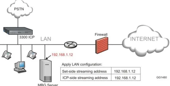
SERVER-ONLY CONFIGURATION ON NETWORK LAN
In this configuration, the server is installed in the customer’s existing network LAN with no exposure to the Internet.
When you select this network profile, the system will use the LAN address of the server for both the set-side and ICP-side streaming addresses of the MBG. This address SHOULD be:
dedicated to the MBG Solution
private
Figure 3. Server-only Configuration Some examples of deployments that use this configuration are:
Secure Call Recording (see page 60)
Daisy Chaining (see page 66)
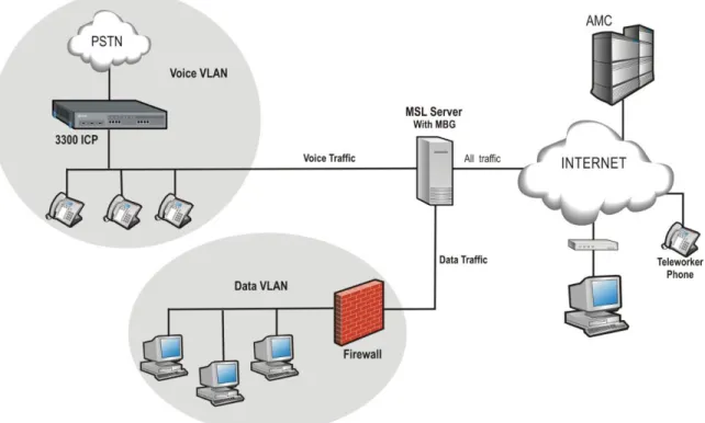
SERVER-GATEWAY CONFIGURATION WITH BRIDGED INTERFACE
The server functions as a firewall/Internet gateway for VoIP traffic, and as a bridge to the WAN interface of the customer’s existing firewall for all other traffic.
When incoming traffic arrives on the server’s WAN interface, it is routed to the appropriate network segment. Voice packets are sent directly to the Voice VLAN and data packets are bridged to the firewall’s WAN interface. By separating the traffic between the voice and data network segments, QoS for voice calls is improved. This setup also enables a Voice VLAN to be installed into an existing Data VLAN without having to update the firewall rules.
With this network profile, the system programs the RTP and data streaming addresses as follows:
STREAM INTERNAL OR ICP-SIDE ADDRESS EXTERNAL OR SET-SIDE ADDRESS RTP LAN interface of server WAN interface of server Data Bridged interface of server WAN interface of server As part of this configuration, you can prioritize voice over data traffic using the MBG’s “Bandwidth Management” feature. Simply program the maximum amount of bandwidth available on the WAN communication links (inbound and outbound). The system employs these settings to establish traffic shaping queues which give priority to voice calls ahead of data traffic.
The external address of the server MUST be
dedicated to the MBG Solution
publicly routable
reachable from the Internet and the internal network (that is, the server should not reside behind a NAT device)
To enable this network profile, the server requires at least three network interface cards: one for the LAN connection, another for the WAN connection, and the third for the bridged connection to the WAN interface of the firewall. As part the Mitel Standard Linux (MSL) installation, you will be prompted to configure the third interface after you have selected the WAN adapter.
The following diagram shows the settings that are applied when the server has a third network adapter that has been configured as a bridged interface and you select Server-gateway configuration on the network edge:
Figure 4. Server-gateway with Bridged Interface Configuration
Note: MSL 9.2 or greater is required to implement “Server-gateway with Bridged Interface”
INSTALLING MIVOICE BORDER GATEWAY
SOFTWARE
This section describes the new installation of MBG on the following platforms:
Physical deployment on a hardware server — page 9
Virtual deployment in a VMware environment — page 12
Virtual deployment in a Hyper-V environment — page 20
If you are upgrading from a previous release, see Upgrading MBG Software on page 69.
BEFORE YOU BEGIN
1. Review the MBG Release Notes available in the Mitel Knowledge Base. 2. Review the MBG Engineering Guidelines available at Mitel OnLine.
3. Ensure that corporate and remote sites meet MBG requirements (see below ). 4. Create an Application Record ID and assign MBG licenses to it.
COLLECT SITE INFORMATION
The following table itemizes the information you will need to enter during software installation and configuration. For efficient installation, gather this information before you start the installation:
ITEM NOTES YOUR INFORMATION
Server Configuration
1. Administrator Password
For password strength, choose a password that contains a mix of upper and lower case letters, numbers, and punctuation characters, and that is not a dictionary word.
2. Domain Name Names must start with a letter; can contain letters, numbers, and hyphens. For more information, see page. 3. System Name
4. IP address of your MSL server
The local IP address of the server where you are installing MSL.
4b. IP address of your external NIC(s)
The IP address of your external Ethernet connection.
4c. Alias IP for your external NIC
A second, alias IP address used for applications that require a server with two IPs (like Audio, Web and Video Conferencing).
5. External Interface Connection
Cable Modem? You need to know if the ISP requires an Account Name OR an Ethernet address as identification in DHCP requests.
DSL Connection? You need to know the username and password for
ITEM NOTES YOUR INFORMATION Direct Connection? You need to know
the static IP address.
6. Gateway IP Address The IP address that your MSL server will use to access the network.
7. DNS Server IP Address
Enter the IP address of your corporate DNS server.
Note: If your DNS is supplied by your ISP, leave this setting blank.
8. Application Record ID #
The number generated when you created an Application Record ID for this product in your AMC account.
"Trusted Network” Access
If your 3300 ICP or some of your users are not on the same subnet as the MSL server, you need to classify them as "Trusted Networks" and then allow them access. Both IPv4 and IPv6 networks are supported. 1. IP Address The IP address of the network for
which you want to allow access 2. Subnet The subnet mask for the range of
IPv4 addresses you wish to allow. 3. Router Access The address of the router/
gateway you will use to access the network (or subnet) to which you are granting access
INSTALLING ON A PHYSICAL SERVER
This section describes the fresh installation of MBG 8.x and MSL 10.x software on a physical server from the MSL Qualified Hardware List.
Download Software from Mitel Online
You can download the MSL and MBG software ISO images from Mitel OnLine and burn CDs or DVDs to take onsite. If the site has limited Internet connectivity, you may also need to perform an offline synchronization with the AMC to retrieve licensing information. (Instructions for offline installation are included in the Installation section.)
To download MSL software from Mitel OnLine:
Note: MSL 9.2 or greater is required to implement “Server-gateway with Bridged Interface”
mode.
Note: Use HTTP or the Software Download Manager to download software.
1. Log on to Mitel OnLine.
2. Move your cursor over Technical and then click Software Downloads.
3. Click MiVoice Border Gateway. The correct MSL load for your software is included on this page.
5. Select a download method: HTTP or the Software Download Manager. 6. Select a location on your PC to store the downloaded software ISO images. To download MBG software from Mitel OnLine:
1. Follow steps 1 to 3 in the "To Download MSL software from Mitel OnLine" procedure above.
2. Click the appropriate MBG software version.
3. Select a download method: HTTP or the Software Download Manager. 4. Select a location on your PC to store the downloaded ISO image.
Build CD/DVDs from the Software
For 32-bit installations of MSL, use a CD. For 64-bit installations of MSL, use a DVD. 1. Insert a CD or DVD into the CD/DVD-ROM drive of the maintenance PC.
2. Navigate to the stored .iso image and double-click the file. Your CD/DVD burner builds the software CD or DVD.
3. Label the discs and take them with you to the installation site.
Install and Configure MSL Software
1. Configure the MBG server to boot from either the CD/DVD-ROM drive.
2. Insert the MSL software CD or DVD into the CD/DVD-ROM drive of the MBG server. 3. Refer to the Mitel Standard Linux Installation and Administration Guide to complete the
following procedures:
Install MSL Software
Configure the Server
Install MBG Software on an Online system
These instructions apply when installing MBG on a server that is connected to the Internet. If you have no Internet connectivity, see Install MBG on an Offline System.
1. Upon reboot of MSL, you are prompted to enter your Application Record ID. You must enter this number to activate the licensing for the site.
2. If you are using a remote management PC on a different subnet than the MBG server, you may need to add the IP address of the PC to the Trusted Networks listing on the MBG server. See the “Networks” topic in the Mitel Standard Linux Installation and Administration Guide. When the required trusted local networks have been configured, proceed to the next step.
3. Open a browser and enter the following URL to access the MSL server manager: https://<IP address or FQDN of MBG server>/server-manager
4. Under ServiceLink, click Blades.
5. Click the Install link associated with the MBG blade. The MBG license agreement appears. (To download the blade for installation at a later time, click the Cache link.) 6. Click Read text to read the license terms for all software applications. If you agree with
the license terms, click Accept all licenses, or click Cancel to exit the blade installation. After you accept all licenses, a progress indicator appears. Note: If you see a “proxy error” message, click Blades (in the server manager menu under ServiceLink) to return to the MSL browser screen.
7. To refresh the page for Internet Explorer browsers, use Click here for automatic update.
8. When installation is complete, an overview of installed components appears. Click Clear this report to return to the Blades panel.
Navigation links for MiVoice Border Gateway and Remote Proxy Services (Web Proxy and Remote Management) appear in the Applications section.
9. In the left-hand menu, under Applications, click MiVoice Border Gateway. For MBG configuration instructions, click the Help icon in the upper right corner of the MBG
interface. To configure remote phones to operate as teleworker devices, refer to the MBG Remote Phone Configuration Guide available at Mitel OnLine.
Install MBG Software on an Offline System
This section describes the fresh installation of MBG 8.x software on a server from the MSL Qualified Hardware List that does not have access to the Internet. Ensure that you have downloaded MBG software and burned a CD or DVD as instructed on page 10.
To Offline Sync with the AMC:
1. Upon reboot of MSL, you are prompted to enter your Application Record ID. Select Next. You are returned to the Linux login prompt.
2. Log in as “admin”. The MSL server console menu is displayed. 3. Select the option to perform Offline Sync with the AMC. 4. In the Offline sync screen, select create.
5. When prompted, insert a portable storage device and then select Next. 6. When prompted, enter your Application Record ID and then select Next.
7. When prompted, remove the storage device and take it to a PC with Internet connectivity. 8. Insert the storage device in the remote PC and navigate to the storage drive location. 9. Search the main directory for a file called sync.bat and double-click it. A script runs that
sends your sync information to the AMC and receives licensekey information in return. 10. To verify the sync, navigate to the sync.log file in the sdata directory of the storage drive
location. Double-click sync.log to open and check for “completed successfully” message. 11. Remove the storage device from the remote PC and go back to the MBG server.
12. Select the option to perform Offline Sync with the AMC. 13. On the Offline sync screen, select read.
14. When prompted, insert the storage device and select Next. The MSL server reads the activation information from the storage device and signals successful completion. 15. Select the option to Exit from the server console. You have successfully performed an
offline activation and your MBG license information is retrieved.
16. Insert the MBG software CD or DVD in the CD/DVD-ROM drive of the server. Complete the installation by following steps 2 through 10 under Install MBG on an Online system on page 10.
INSTALLING IN A VMWARE VIRTUAL ENVIRONMENT
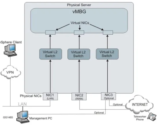
Virtual MBG (vMBG) allows you to deploy MBG as an appliance within a VMware virtualized environment. Virtual MBG supports the same server configurations as the physical server MBG (see Network Profiles on page 3).
Figure 5. Typical Virtual MBG Appliance
VMware Resources
This section explains the installation of the virtual MBG appliance. Refer to the VMware documentation for a description of the setup and operation of the vCenter Server and the vSphere Client.
Virtual MBG is supported on the following platforms:
For a list of the VMware vSphere software product versions supported by MBG, see the
Virtual Appliance Deployment Guide on the Mitel Customer Documentation site at
http://edocs.mitel.com/
See the VMware main documentation page at https://www.vmware.com/support/pubs/ for links to the following information:
- New Features and Release Notes
- Hardware and Software Compatibility Information
- System Administrator Documentation (Main Documentation Set plus additional resources)
- Optional vSphere Products and Modules - Automators and Customizers
See the VMware Compatibility Guide at
http://www.vmware.com/resources/compatibility/search.php for supported hardware platforms.
For vSphere tutorials and training videos/demos, go to http://www.rtfm-ed.co.uk/vmware-content/vsphere-videosdemos/.
Installation Requirements
The following requirements apply to virtual MBG installations:
Virtual MBG requires vSphere platform software installed on a VMware vCenter Server. For a list of supported software versions, see the Virtual Appliance Deployment Guide on the Mitel Customer Documentation site.
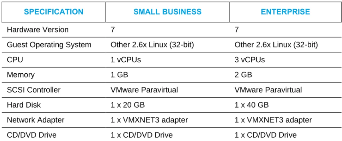
Virtual MBG requires the minimum hardware platform specifications listed in Table 1 for the VMware vCenter server. You can use the Summary tab in the vSphere Client interface to view or change the hardware settings that are automatically selected when the system is installed. Ensure that your system meets or exceeds the specifications listed below:
Table 1. VMware Minimum Hardware Platform Specifications
SPECIFICATION SMALL BUSINESS ENTERPRISE
Hardware Version 7 7
Guest Operating System Other 2.6x Linux (32-bit) Other 2.6x Linux (32-bit)
CPU 1 vCPUs 3 vCPUs
Memory 1 GB 2 GB
SCSI Controller VMware Paravirtual VMware Paravirtual
Hard Disk 1 x 20 GB 1 x 40 GB
Network Adapter 1 x VMXNET3 adapter 1 x VMXNET3 adapter CD/DVD Drive 1 x CD/DVD Drive 1 x CD/DVD Drive
VMware ESX/ESXi release 4.0 or later installed on an Intel-based server with a minimum Xeon 55xx Series @ 2Ghz or better (supporting Core i7/Intel Nehalem architecture), with hyper-threading enabled.
vSphere Client installed on a Windows workstation. Refer to the VMware website for detailed installation procedures and additional documentation.
(Optional) vCenter Server deployed on the network. Refer to the VMware website for detailed installation procedures and additional documentation.
Internet access to allow licensing from the Applications Management Center (AMC). Offline synchronization is not supported with virtual deployments.
A DNS server that is reachable from the platform.
Latest virtual MBG software in a .ova archived file from Mitel Online (part number 54005339). This archive of .ova files contains the OVF 1.0 descriptor and VMDK file. The following constraints apply:
Virtual MBG is not supported if you manually install MBG (that is, install the MSL and the MBG software into a VMware virtual machine and then use a virtual MBG Application If you experience low transfer speeds though a Virtual MBG that is operating in server-gateway mode, it may be necessary to adjust the Large Receive Offload (LRO) settings, which are located in the vSphere client application under Configuration > Advanced Settings > Net. For up-to-date information on this issue, check the VMware knowledge base at http://kb.vmware.com/; for example
Record ID to activate the software). Virtual MBG is only supported if you install it from the virtual MBG .ova file.
Migration of a physical MBG system database backup to a virtual MBG deployment is not supported. Virtual MBG deployment s do support application data backup and restore, however.
Pre-installation Checklist
Identify vSphere deployment mode. You can deploy vSphere in either “Standalone” or “Managed” mode:
- vSphere Standalone mode is used when you run virtual MBG as a hypervisor or ESX/ESXi host.
- vSphere Managed mode is used when the virtual MBG hypervisor host is managed by a vCenter Server instance. vCenter Server is the “management” server that enables many of the optional vSphere features not available in Standalone mode (for example, vMotion, High Availability, Site recovery manager, vCenter plugins).
Identify the virtual MBG server configuration. See Server Configurations for more information.
Identify the virtual MBG deployment configuration. The following table lists the user limits and hardware resource requirements of the virtual MBG appliance as defined in its .ova template for the supported deployment configurations. The template enforces these minimum specifications during deployment.
Table 2. Virtual MBG User Limits and Hardware Resource Requirements DEPLOYMENT
CONFIGURATION
USERS RAM VCPU HARD DISK
STORAGE
Total Reserved Total Reserved Total Reserved
Small Business Multi-Application 150 1 GB 1 GB 1 vCPU 1000 mHz 20 GB 15 GB Enterprise Multi -Application 500 2 GB 2 GB 3 vCPUs 3000 mHz 40 GB 35 GB
Note: You can use the Summary tab in the vSphere Client interface to set or view the hardware specifications of a deployed NuPoint instance. Ensure that you meet or exceed the minimum resource requirements listed in the table.
Collect Properties
The following table itemizes the information you will need to enter during software installation and configuration. For efficient installation, gather this information before you start the installation:
ITEM NOTES YOUR INFORMATION
Localization
Time zone setting Identify the MSL operating system time zone setting. The default is America/New York. The Time zone setting also determines your system telecommunications regional settings.
Keyboard Type Identify the preferred keyboard type (default is us).
Application
Initial Administrator Password
Record the initial administrator password for the MSL server manager interface. This password must be at least six characters long. When you access the server manager, you will be prompted to change this initial password.
Note: You must enter a password before you deploy the system; otherwise, the system will not boot up.
Initial server manager Administrator Password:
___________________________ Final server manager
Administrator Password:
___________________________ It is recommended that you use a strong password that contains all of the following: upper case letter, lower case letter, number, non-alphanumeric character, and be at least seven characters long. Do not use a commonly used word (for example: 'password'). Hostname Set the hostname of the system.
Domain Name (Optional)
Specify the domain name for the hostname above. The default domain name is
ITEM NOTES YOUR INFORMATION License Key (Optional) Identify the License Key (ARID) for
this system. The ARID is used by the AMC to distribute the system licenses.
DNS Server (Optional) Record the IP address of your corporate DNS server.
Note: If your DNS is supplied by your ISP, leave this setting blank. Remote Network
Address for server administration (Optional) Remote Network Netmask (Optional)
Network Settings
LAN IP Address Record the IP address of the local (LAN) interface. This must be a valid IP address on the local LAN.
Note: You can leave this field blank if you are creating a blank template of the OVA file for cloning.
However, you must set it before powering up the virtual appliance. You can set this IP address from vSphere Client. Right-click on the MiCollab and click Edit Settings. Click the Options tab, click
Properties and enter the LAN IP Address.
LAN Netmask Record the Netmask of the LAN WAN IP Address
(Optional)
For Network Edge (Server-gateway) deployments, record the IP address of the external (WAN) interface. This must be a valid IP address on external WAN. For LAN only (Server-only) deployments, use an IP address of 0.0.0.0.
Note: You can leave this field blank if you are creating a blank template of the OVA file for cloning.
However, you must set it before powering up the virtual appliance. You can set this address from vSphere Client. Right click on the MiCollab and click Edit Settings. Click the Options tab, click
Properties and enter the WAN IP
Address. WAN Netmask
(Optional)
Record the Netmask of the WAN.
LAN (Optional) Optional network interface that can be used to connect a management application or to route the SIP
ITEM NOTES YOUR INFORMATION Proxy to an isolated SIP Proxy
network. Default Gateway IP
Address
Record the Gateway IP address. For Server-gateway deployments this gateway typically points to the internet.
For Server-only deployments, this gateway typically points to a LAN router.
For additional information concerning VMware deployments, refer to the Mitel Virtual Appliance Deployment Guide available at Mitel OnLine.
Deploy Virtual MBG Appliance
You deploy the virtual MBG vApp as an image in OVF 1.1.0 package format (file suffix of .ova). The virtual MBG .ova file contains the VMware tools, MSL operating system and MBG software as a pre-installed image. The MBG vApp is unique from the other MBG software application files.
Typically, you deploy virtual appliances into the vSphere environment from the vSphere Client application that runs on a Windows PC. However, you can also use the command-line
ovftool to deploy vApps (from .ovf or .ova files). Both methods involve deploying an OVF Template. You can deploy an OVF template from any local file system that is accessible from the vSphere Client machine or from a remote web server.
To deploy Virtual MBG:
1. Obtain the virtual MBG VMware .ova archive file from Mitel Online: - Launch a web browser on the vSphere Client PC.
- Log in to Mitel Online at https://www.ebiz.mitel.com. - Click Technical and then click Software Downloads. - Click MiVoice Border Gateway.
- Click the appropriate virtual MBG Software Download version:
MiVoice Border Gateway Standalone Download - Server and VMware Installs - Review the Release Notes.
- Verify that the versions of the software and applications are correct. - Download the required .ova file by clicking the link in the table.
- Select a download method: HTTP or the Software Download Manager. - Select a location on your vSphere Client PC to store the downloaded .ova file. 2. Launch the vSphere Client application on the network PC.
- Click Start > All Programs.
- Click VMware > VMware vSphere Client.
- Enter the IP address or hostname of the Hypervisor ESX/ESXi Host server OR enter the IP address or hostname of the vCenter Server.
- Enter your username and password. - Click OK.
3. In the vSphere Client application screen, click File > Deploy OVF template . . . The
4. Do one of the following:
Deploy from file: if the OVF template file was downloaded to the local computer or to a network share drive, then click Browse to locate the file. (On Microsoft Vista systems, select .ova in the File Type list.)
Deploy from URL: if the OVF template file is on the internet or accessible through a web browser; enter the URL of the location of the file.
5. Click Next. The OVF Template Details screen displays. The Version field identifies the version of the virtual MBG preinstalled software.
6. Click Next. The End User License Agreement screen displays.
7. Click Accept to accept the license agreement, then click Next. The Name and Location
screen displays.
8. Enter a meaningful name for this virtual MBG instance or accept the default name. Enter a folder location within the inventory if the vSphere Client is connected to an ESX/ESXi host. Click Next. The Deployment Configuration screen appears.
9. Choose the required deployment configuration for your site from the drop-down menu: Small Business or Enterprise. After you select a deployment configuration, user limits and required hardware resources are displayed on the screen. Click Next. The following three steps are dependent on your configuration.
10. If you are using the optional vCenter Server, select the appropriate Host/Cluster for this deployment. Click Next.
11. If you are deploying virtual MBG in a vCenter Server, select the Resource Pool for the virtual MBG instance. Click Next.
12. If multiple datastores are available, select the Datastore where the virtual machine files will be stored. Click Next. The Disk Format screen appears.
13. Select Thick Provision Lazy Zeroed. Selecting any other option, such as Thin
Provisioning, can cause voice quality issues due to disk sharing. Click Next. The Network Mapping screen appears.
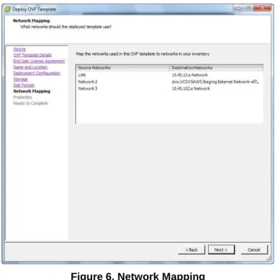
14. Configure the network mapping. (This screen is only displayed if the network defined in the OVF template does not match the name of the template on the host to which you are deploying vMBG.)
Figure 6. Network Mapping
The required settings are dependent on your deployment configuration:
Network Edge (Server-Gateway) Mode: In this configuration mode, the server functions a firewall/Internet gateway with two Ethernet interfaces. One interface is connected to the internal network (LAN) while the other is connected to the external network (Internet). Select the destination LAN and WAN networks for the OVF template. These are the "Associated Networks" that are assigned in the LAN and WAN IP Pools. You must assign the LAN and WAN destinations to different networks.
LAN Only (Server-only) Mode: In this configuration mode, the server is only
connected to the internal network (LAN). For this mode, only select a destination LAN network for the OVF template.
LAN (Optional): This interface can be used to connect a management application or to route the SIP Proxy to an isolated SIP Proxy network.
Contact your Data Center administrator for more details about which network mapping to use.
15. Click Next. If you are deploying on vCenter, the Properties screen appears. You can use this screen to configure the MSL operating system parameters. Complete the fields in this screen using the information that you gathered above. Mandatory fields are highlighted with a red border.
You must specify both the LAN IP and WAN IP addresses. Otherwise, the virtual appliance will not power on. If you are deploying the virtual machine in LAN only (server-only) mode set the WAN IP address to 0.0.0.0.
For Network Edge deployments, ensure that the LAN IP and WAN IP addresses are on different subnets and the Gateway IP address is on the subnet of the WAN IP address.
You can only use this screen to set the LAN IP and WAN IP addresses for the initial deployment of the appliance. After initial boot-up, you must use the MiCollab server console interface to modify the LAN IP or WAN IP addresses.
Note: To create a blank template for cloning, leave the following fields empty: Administrator Password, Hostname, Domain Name, LAN and WAN IP addresses. After you create the clone, you must complete these fields before you can proceed with deployment. You cannot clone an active (deployed) virtual machine.
16. Click Next. The Ready to Complete screen appears.
17. Review the information and click Finish. vSphere starts the deployment of virtual MBG on the server. A progress bar is displayed.
18. After the dialog indicating that the deployment is complete appears, click Close. The virtual MBG vApp appears in the inventory list in the left side navigation pane.
Configuration
1. To launch the MSL server console:
- right-click on the virtual MBG name in the inventory list and click Power > Power On. - right-click on the virtual MBG name again and then click Open Console. MSL boots
and the server console appears. Click inside the console window to continue. To release the cursor for other desktop activities, press CTL + ALT.
2. Do one of the following:
If you deployed vMBG on vSphere vCenter and used the Custom Template to configure the MSL Operating System parameters, you can log in to MSL and begin using MBG.
If you did not use vSphere vCenter, you must follow the instructions in the Mitel Standard Linux Installation and Administration Guide to configure the MSL operating system. You may be prompted to Install applications from CD/DVD? Select No. If you are unsure if you have the latest version of MBG software, access the Blades panel in the MSL console and check for available upgrades.
Notes:
If the Mitel Virtualization Framework requires upgrading, the MVF blade will appear on the Blades panel. Install it to take advantage of optional VMware features such as SRM and High Availability.
If the MSL server lacks direct access to the Internet, you can connect to the AMC by opening a pinhole in your firewall or by configuring a licensing proxy server to perform port forwarding. For implementation details, see the MSL Installation and
Administration Guide and the Mitel Virtual Deployment Guide. Offline synchronization is not supported by virtual deployments.
3. In the left-hand menu of the server manager, under Applications, click MiVoice Border Gateway. For MBG configuration instructions, click the Help icon in the upper right corner of the MBG interface. To configure remote phones to operate as teleworker devices, refer to the MBG Remote Phone Configuration Guide available at Mitel OnLine.
INSTALLING IN A MICROSOFT HYPER-V VIRTUAL ENVIRONMENT
If you are installing MBG in a Microsoft Hyper-V environment, refer to the to Virtual Appliance Deployment Guide for hardware and software requirements. After you have done this and
created the virtual machine, use the "physical" software installation procedure to install the MBG virtual application.
Limitations
Although you use the physical software installation procedure to install vMBG, you must assign a virtual product license to the ARID.
Hyper-V virtual machines that run Mitel Standard Linux (MSL) do not support connection of USB devices. Accordingly, the MSL software installation must be performed from the CD/DVD-ROM drive.
Mitel software must be installed using traditional physical ISO images available from Mitel OnLine. OVA images cannot be used. After creating the virtual machine, use the ISOs to install the MSL operating system and MBG application software as you would on a physical system.
Once the software has been installed and licensed, Hyper-V must maintain online connectivity to the AMC and is subject to the same Sync Expiry rules in place for VMware-based deployments.
To achieve the same perfornance as VMware, a Hyper-V virtual machine requires twice as many virtual processors.
DISABLING THE MBG SERVICE
Disabling the MBG service can be done immediately or can be queued until all currently active calls are completed (“Courtesy Down”).
Note: Calls that are in the “Calling”, “Hold”, or “Transfer” state are not maintained. (In a clustered environment, you can make a node shut down more gracefully by setting its Cluster Weight to zero before disabling. This ensures that the node remains in service until all sets are idle for at least 30 seconds. For more information about setting Cluster Weight, see the MBG online help.)
To shut down immediately:
4. On the MBG main page, click the System status tab and then click Dashboard. 5. Click Stop.
6. Click OK to confirm the immediate shutdown.
To shut down after all currently active calls are completed:
1. On the MBG main page, click the System status tab and then click Dashboard. 2. Click Courtesy Down.
3. Click OK to confirm the Courtesy Down shutdown.
ENABLING THE MBG SERVICE
When you access MBG, the web interface opens on Dashboard screen which displays the MBG status, Clustering status, and licensing information.
Note: You must select a Network Profile before you can enable the MBG service. See page 3. To enable the server:
1. On the MBG main page, click the System status tab and then click Dashboard. 2. Click Start. MBG starts and is enabled.
TELEWORKER SERVICE
This section contains corporate and remote location software, hardware, and
connectivity/network requirements necessary to support the teleworker service of the MiVoice Border Gateway Solution.
CORPORATE LOCATION REQUIREMENTS
Hardware
Please refer to the MSLQualified Hardware List, available at Mitel OnLine, for hardware combinations that have been tested in Mitel's labs.
For deployments of less than 100 sets, select an entry class server.
For deployments of 100 to 500 sets, select a mid class server.
For deployments of 500 or more sets, please contact Mitel Sales Engineering.
For cluster deployments, each server in the cluster should have the same, or similar, processor capacity.
Software
ITEM REQUIREMENT
MSL software Release 10.0 running MBG 8.0 software blade (includes Remote Proxy Services with Web Proxy & Remote Management)
Communication Platforms
ITEM REQUIREMENT
MiVoice Business (3300 ICP)
Release 4.0 or later
MiVoice Office 250 Version 6.0 or later
Phones/Devices
For a complete list of devices that are supported by MBG and its services, please refer to the
MBG Remote Phone Configuration Guide available at Mitel OnLine.
License Requirements
MBG licenses are available in various quantities. For detailed licensing information, see Upgrading MiVoice Border Gateway Licenses on page 73.
Each MBG service requires licensing as follows:
Teleworking service: Each teleworker device requires an “MBG Upgrade: TW service” license. Licenses are available in packages of 1, 10, 25 or 50.
Secure recording connector service: You need a quantity of “Secure Recording Connector” licenses equal to the total number of concurrent recording ports you will use. (A “port” corresponds to the recording of a two-party or multi-party conversation.) Licenses are available in packages of 1, 10, or 50.
IPv6 service: For IPv6 interface support, you require one “IPv6 License for MBG.” SIP Trunking service: For SIP Trunking support, you require one “MBG: 1 SIP Trunking
Channel License” for each of the maximum number of simultaneous calls you estimate that you will make.
Web Proxy and Remote Management: No license is required to use these services.
Transcoding (Compression) Licenses:
- For MBG: You can configure MBG to compress the voice streams to and from remote devices. You need a compression license for each call that will concurrently run G.729. Note: Enabling G.729 transcoding may degrade voice quality. In addition, it increases the load on the server’s CPU which may reduce the number of
simultaneous calls the server can handle. If the ICP has the appropriate compression licenses and is programmed to make the licenses available to the remote sets, use these licenses instead.
You can also configure set-side compression to apply a compression codec to the voice traffic going to remote sets. See the “Configure Transcoding” topic in the MBG online help for more information.
- For SRC: The CRE may request that the voice stream be compressed. In this case, when properly provisioned with compression licenses, SRC automatically applies compression to the stream that it sends to the CRE. One compression license is
required per recorded call. If there are no licenses available, SRC continues to send the voice stream but it is not compressed.
Software Assurance
The Mitel Software Assurance (SWA) Program is a subscription-based service that provides customers with access to new software releases, updates, functionality and product support services for all users (ports) on a given application record. The Mitel Applications
Management Center (AMC) manages the entitlement of the Software Assurance Program, determining whether a given application record ID for a customer is entitled to a specific software installation or upgrade. Initial product purchase includes 13 months of Software Assurance. The program can then be renewed for your chosen term. (Note: Discounted rates are applied to multi-year renewals.)
Renewing Software Assurance
Your Authorized Mitel Reseller will contact you before the expiry of your Software Assurance term to assist you with the renewal process. When you have decided upon a renewal term (from 1 day to 4 years), your Mitel Reseller will supply a price quotation. Upon acceptance of the quotation, your Mitel Reseller places your order and your Software Assurance is renewed within minutes. Note: If your software assurance plan has expired, you can still renew it, but there will be a re-enlistment fee.
For more information about Software Assurance: 1. Log into Mitel Online.
2. Under Services, click Software Assurance.
Firewall Requirements
When using the MBG server behind a firewall, the firewall must have the following capabilities:
At least three physical interfaces:
Internal network
External network / Internet
DMZ
Must preserve TCP and UDP port numbers used on the external address of the firewall when the packets are passed to the MBG server in the DMZ.
Must provide static network address translation between an externally visible address and the DMZ address of the MBG server.
SIP awareness must be disabled.
Note: Firewalls with only two ports are not supported even though they may be able to simulate a DMZ using port forwarding.
For a detailed list of required firewall settings, refer to the MBG Engineering Guidelines
available at Mitel OnLine.
SUPPORT FOR HTML APPLICATIONS
MBG has the ability to automatically fetch HTML applications from ICPs and make the files available for downloading by teleworker devices. For example, Mitel IP Phones located on the Internet can download a screensaver HTML application from an ICP via MBG.
A list of of valid HTML applications in maintained by MBG. This list is updated periodically when MBG fetches the latest versions of the applications from the ICPs.
Notes:
MBG does not support HTML applications that require continual access to internal network in order to function.
To facilitate downloading HTML applications from the ICP, firewalls must allow TFTP traffic between the MBG and ICP. Refer to the engineering guidelines for details.
REMOTE LOCATION REQUIREMENTS
To support the teleworking service of MBG, each remote location requires the following components:
IP/SIP Phone(s) from the list of supported phones.
Broadband Router (Internet Gateway) that provides NAT and local DHCP.
Sufficient Internet bandwidth to support any other Internet traffic that uses the same link, such as web browsing. The connection must terminate on an Ethernet device.
Each remote location also requires a broadband Internet connection that provides - a bandwidth of at least 50 Kbps, bi-directional, if G.729a compression is enabled at
the corporate site, or
- a bandwidth of at least 100 Kbps, bi-directional, if G.729a compression is not enabled at the corporate site.
For bandwidth requirement calculations, refer to the MiVoice Border Gateway Engineering Guidelines.
Phones/Devices
The remote location must meet the following requirements:
COMPONENT DETAILS NOTES
Supported IP Phones For a complete list of devices that are supported by the teleworking service of MBG, please refer to the MBG Remote Phone Configuration Guide available at Mitel OnLine. Supported Mitel
peripherals
5305 IP Conference Unit 5310 IP Conference Unit Line Interface Module
Cordless Module and Accessories IP Programmable Key Module (PKM)
Some peripherals are listed in the MBG Remote Phone Configuration Guide.
Maximum IP Phones per Remote Site
Bandwidth must be provisioned for all Internet traffic, including applications other than the MBG Solution application.
Note: Maximum number of sets per remote site may be adversely affected by router performance.
Network Parameters
COMPONENT DETAILS NOTES
Subnet Mask
Default Gateway IP Address
Teleworker Gateway IP Address Manually programmed into the IP Phone (see the MBGRemote Phone Configuration Guide
available at Mitel OnLine)
Router/Internet Gateway
In addition to a supported phone, the remote location requires a broadband router (or Internet Gateway) that provides NAT and local DHCP. This device will allow both your phone and PC to share the single IP Address provided by your Internet Service Provider.
Note: MBG is not supported in situations that require specific software to be loaded on the PC to manage the connection. (For example, AOL broadband.)
CONFIGURE TELEWORKER SERVICE
The following procedure descibes how to configure the Teleworker Service on MBG and the remote SIP and MiNet devices.
Configuring the Teleworker Service on MBG
To configure the teleworker service on MBG:1. Access the MSL server manager and click MiVoice Border Gateway under Applications. 2. Add the ICPs that are connected to MBG:
a. On the MBG main page, click the Service configuration tab and then click ICPs. b. Click the sign.
c. Enter a Name of the ICP (for example, ICP1). d. Enter the Hostname or IP Address of the ICP.
Note: For MiVoice Office 250 systems equipped with a Processing Server (PS-1), enter the hostname or IP address of the PS-1. SIP traffic will then point to the PS-instead of the base MiVoice Office 250.
e. For Type, select either MiVoice Business or MiVoice Office 250.
f. Enter the Installer password for this ICP. The password is supported only on MiNet phones, not on MiCollab Client softphones, Spectralink phones, or SIP phones. Valid characters include 0 to 9, *, and #.
g. Select the SIP Capabilities to support: UDP; UDP, TCP; or UDP, TCP, TLS. Ensure that this setting matches the capabilities of the ICP. For example, select UDP, TCP, TLS for MiVoice Business or UDP for MiVoice Office 250.
h. Select Indirect call recording capable to allow MBG to provide a secure recording connector (SRC) service to remote MiNET devices registered on the ICP.
i. Click Save.
j. Repeat for all other ICPs connected to MBG. 3. Configure the default ICP(s) for MBG:
a. On the MBG main page, click the Service configuration tab and then click ICPs. b. In the ICP listing, locate the ICP that will be your default.
- Select the Default for MiNet ICP.
- Select the Default for SIP ICP. You can select the same ICP for both roles. d. Click Update Default ICPs.
4. Enable the server:
a. On the MBG main page, click the System status tab and then click Dashboard. b. In the MBG status box, click Start. MBG starts and is enabled.
Note: You must select a Network Profile before you can enable the MBG service. See page 3.
5. Provision the teleworker devices:
To provision devices using the web interface, see Provisioning MiNet Devices and
Provisioning SIP Devices.
To provision devices using a CSV file, see Bulk Provisioning of MiNet and SIP Devices.
Notes:
Following a software upgrade, reconfiguration is not required other than to add new hardware (ICPs or devices).
After completing the initial installation, run the Basic connectivity test on Diagnostics page. The test confirms connectivity to ICP signaling services such as MiNet, SIP and TFTP.
Provisioning MiNet Devices
MiNet is Mitel's proprietary signaling protocol used to control Mitel IP and TDM devices. MiNet devices in a teleworker environment can take advantage of the same features and functionality as they would when connected directly an ICP.
Note: When using MBG in conjunction with MiNet devices on a MiVoice Business, set the NAT Address Type for the devices to Native (this setting is located under System > Devices and Feature Codes > Trunks > <trunk number>).
There are three ways to add MiNet devices to MBG:
Auto-configuration
Manual Configuration
Unrestricted Access
Note: In addition to configuring the MiNet devices with the web interface, you can also configure them in a CSV file. For details, see Bulk Provisioning of MiNet and SIP Devices.
Auto-configuration of MiNet Devices
Use this procedure to enable your MiNet devices to connect to MBG automatically. To program auto-configuration of MiNet devices:
1. On the MBG main page, click the Service configuration tab and then click ICPs. 2. Do one of the following:
To add a new ICP, click the sign.
To update an existing ICP, locate in the list and click .
3. Enter the Installer password between five and 10 characters in length. Valid characters include 0 to 9, *, and #.
4. Click Save.
5. Repeat for other ICPs as required.
6. On the remote MiNet devices, program the following:
For TELEWORKER GATEWAY, enter the public IP address of MBG.
For TW INSTALL PW, enter the Installer Password of the ICP.
Note: Field names vary by device. For valid field names and complete programming instructions, refer to the MBG Remote Phone Configuration Guide available at Mitel OnLine. The programmed remote MiNet devices may now register with MBG. They automatically appear on the MiNet devices screen with default values and a status of "enabled". If the devices are already listed on the ICP, they will be registered autotomtically. If they are not yet listed, then the devices will request a PIN number from the ICP before completing
registration.
Manual Configuration of MiNet Devices
Use this procedure to manually configure MiNet devices in a teleworker environment. Manually provisioning devices is recommended if you have a limited number of devices.
Note: Complete this procedure only if an installer password (auto-configuration) is not implemented.
To manually provision MiNet devices:
1. On the MBG main page, click the Service configuration tab and then click MiNet devices.
2. Click the sign.
3. Select Enabled to enable the set and allow it to connect to the ICP 4. Enter the MAC address of the phone.
5. Update other fields as required. 6. Click Save.
7. Repeat for all MiNet remote devices connected to MBG.
Unrestricted MiNet Devices
Use this procedure to disable the requirement for MiNET devices to authenticate themselves. This enables any MiNet device to register without a password, provided that it is listed on the default ICP.
Because MBG simply passes the MiNet devices to the ICP for registration, this method should restricted to LAN-based teleworker implementations. It should not be used for MiNet devices located on the Internet.
To enable unrestricted MiNet device access:
1. On the MBG main page, click the System configuration tab and then click Settings. 2. Under MiNet options, clear Restrict MiNet devices.
3. Click Save.
4. On the remote MiNet devices, program the following:
For TELEWORKER GATEWAY, enter the public IP address of MBG.
Note: Field names vary by device. For valid field names and complete programming instructions, refer to the MBG Remote Phone Configuration Guide available at Mitel OnLine.
The programmed remote MiNet devices may now register with MBG. They automatically appear on the MiNet devices screen with default values and a status of "enabled".
Provisioning SIP Devices
To configure SIP Devices requires licenses enabled on the MiVoice Business. SIP devices are added in a similar fashion to other devices on the MiVoice Business by using either the “User Configuration” or “Multiline IP Set Configuration” form in the MiVoice Business System Configuration Tool.
MBG cannot disable restricted login by SIP devices. This means is that all SIP devices must be programmed on the MBG before being presented to the ICP.
Notes:
In addition to configuring SIP devices with the web interface, you can also configure them in a CSV file. For details, see Bulk Provisioning of MiNet and SIP Devices. For MiVoice Office 250 implementations, select Yes for the Use Registered
Username value of the SIP phone profile group (this setting located under System > Devices and Feature Codes > SIP Peers > SIP Phone Groups on the MiVoice Office 250).
Manual Configuration of SIP Devices
Use this procedure to manually configure SIP devices in a teleworker environment. To manually provision SIP devices:
1. On the MBG main page, click the Service configuration tab and then click SIP devices. 2. Click the sign.
3. Select Enabled to enable the set and allow it to connect to the ICP.
4. For Set-side username, enter the set-side (MBG side) user name for the SIP client you want to authorize.
5. For Set-side password, enter the set-side password for the SIP client you want to authorize. Then enter the Confirm set-side password.
6. For ICP-side username, enter the Username that this SIP client uses to access the ICP. 7. For ICP-side password, enter the password that this SIP client uses to access the ICP.
Then enter the Confirm ICP-side password.
Note: Leaving the two preceding fields blanks causes the ICP-side credentials to default to the same values as set-side credentials This may not match the password configured in the ICP, causing connections for this set to be denied. We recommend that you enter both SIP- and ICP-side credentials for more secure authentication.
8. Update other fields as required. 9. Click Save.
10. Repeat for all SIP remote devices connected to MBG. 11. On the remote SIP devices, program the following:
For User Name, enter the SIP-side username.
For Password, enter the SIP-side password.
For SIP Registrar or Domain, enter the public IP address of MBG.